Page is loading ...

analog and digital systems
6 4 1 i s
owners manual
-3009 REV A
©2001 analog and digital systems, inc.
1.800.255.4434 www.adst.com


1
introduction..................................................................................... 1
about this manual............................................................................ 1
features of your 6-series loudspeaker............................................... 2
warnings and tips............................................................................. 3
system planning............................................................................... 3
amplifier requirements...................................................... 4
mounting locations.......................................................................... 4
controls and connections................................................................. 4
tweeter level control........................................................ 4
connections to the amplifier.............................................. 5
speaker wiring.................................................................................. 5
speaker wire selection....................................................... 5
polarity and phasing.......................................................... 5
termination....................................................................................... 6
speaker mounting............................................................................. 6
mid / woofer installation................................................... 6
mid / woofer mounting..................................................... 6
tweeter installation............................................................................ 8
surface mount.................................................................... 8
surface mount cup mounting............................................. 8
flush mount....................................................................... 8
blind installation................................................................. 8
tweeter mounting.............................................................. 8
crossover installation.......................................................................... 10
connecting the system........................................................ 10
connections to crossover network and radio or amplifier.... 10
tri-amplified connections to the crossover network............. 10
tri-wired connections to the crossover network............. 10
troubleshooting................................................................................. 13
jack pinouts....................................................................................... 14
specifications..................................................................................... 14
warranty information......................................................................... 15
ce declaration of conformity............................................................... 16
introduction
Thank you for choosing this a/d/s/ component automotive loudspeaker. Your new loudspeaker system
is the latest innovation in reference quality automotive loudspeakers. Its unique combination of high
technology design and real-world convenience features make it the ideal addition to any quality music
system. a/d/s/ takes great pride in manufacturing products that truly stand the test of time, from their
renowned mini-speakers to whole house systems of the grandest proportion. With a minimum of care,
this a/d/s/ product will provide years of trouble-free satisfaction. Keep this manual in a safe place, it’s
likely you will use it again & again!
about this manual
To get the most from your a/d/s/ 6-series loudspeaker, we recommend that you read this manual thor-
oughly before using. If there is anything that you do not fully understand, please consult with your
a/d/s/ dealer before attempting the installation.
anufacturer’s name: analog and digital systems, inc
anufacturer’s address: 9235 south mckemy street
tempe arizona 85284
usa
clares, that the product:
product name: 641is
nforms to the following standards:
EN 50 081-1/1992
EN 50 082-1/3.1995
european contact:
Axel Perlwitz
audiomax GmbH
Heilbronn Germany

15
ded woofer basket -the back bone of any good woofer is it’s basket. It provides the proper align-
nt and support structure for the magnet while the very thin braces guarantee a minimum of early
ections off the basket that would be ordinarily transmitted as sonic colorations through the cone.
eter level control - a three position control adjusts the volume of the tweeter with respect to the
range.
ti-mount tweeter - all of the tweeter mounting options (surface, flush, or angled flush) are sup-
d with the 6 series systems to mount the high quality ferrofluid cooled neodymium tweeter.
formal tweeter grille - the tweeter grille conforms to the exact shape of the dome over it’s entire
ace radiating area to assure that it is truly transparent at all listening angles, not just directly on axis.
amplifiable / tri-wireable - the passive crossover supplied with this system is tri-amplifiable or tri-
able; typically only available in high quality audiophile home loudspeakers.
d state tweeter protection - advanced protection circuitry provides protection for the tweeter
nst overpowering or amplifier clipping.
flite III woofer cone - mineral enhanced copolymer which is injection molded to provide the ideal
nce of mass to stiffness.
ted voice coil -magnet structure cooling vent enhances power handling capabilities of the woofer.
ended center pole - woofer magnet geometry provides a symmetrical magnetic pattern to reduce THD.
There are two things you must do to ensure trouble free service in the event you need warranty repairs.
1 - Keep your original sales receipt in a safe place. A copy of the receipt will be re q u i r ed to obtain warranty serv i c e .
2 - Be sure your retail dealer has written the date, the model number, and the serial number (if applicable) of
the Product on the receipt.
To give yourself an extra measure of protection, make a separate re c o rd of the information about your purc h a s e
and keep it in a safe place. In the event you misplace the sales receipt, your dealer may be able to give you a
c o p y.
Take a moment now to read the terms of your warranty. Check to be sure your sales receipt is dated and has
the Product model number and serial number (if applicable) on it. Then put it away in a safe place.
When shipping a Product in for service:
• Enclose a copy of your original sales receipt that has the date, the Product model number and serial
number (if applicable) written on it.
• Always ship Products in the complete original packing material.
• Avoid shipping Products via the Postal service. If you must use the Postal service, be sure to register
and insure the package.
a/d/s/ Limited Warranty
Analog and Digital Systems, Inc. (a/d/s/) warrants to the original consumer purchaser of the a/d/s/ Products
described in this manual, that the Product will be free from defects in materials and workmanship for a period
of one (1) year after the date of purchase. If the product is installed by an authorized a/d/s/ retail dealer, the
warranty is extended to three (3) years, a/d/s/' sole obligation under this warranty shall be to provide, without
charge, parts and labor necessary to remedy the defects, if any, that appear during the warranty period.
This warranty is the sole and exclusive express warranty given with respect to the Product. All other express war-
ranties are hereby excluded. Neither a/d/s/ nor the authorized dealer who sells the Product is responsible for
indirect, incidental, or consequential damages. Some states do not allow the exclusion or limitation of inciden-
tal or consequential damages, so the above limitation or exclusion may not apply to you. This warranty gives
you specific legal rights and you may also have other rights which vary from state to state.
IMPORTANT - Keep your original sales receipt. Be sure the retail dealer has written on it the date, model num-
ber, and serial number (if applicable) of the Product. This information is required for warranty service.
This warranty is limited to:
• Products purchased from authorized a/d/s/ retail dealers in the United States. a/d/s/ will supply a list
of authorized dealers on request.
In order to obtain warranty service you must:
• Return the Product, freight prepaid, to the a/d/s/ dealer from which it was purchased. If necessary
you may call a/d/s/ Customer Service Department for the names and addresses of authorized deal
ers in your area.
• Provide proof of purchase in the form of a copy of your original sales receipt. The date, model
number, and serial number (if applicable) of the Product must be written on the sales receipt.
This warranty does not cover:
• Damage that is the result of misuse, abuse, accident (including but not limited to damage by
water), faulty hookup, defective or maladjusted associated equipment, or the use of the Product
with
equipment for which it was not intended.
• Cosmetic defects that appear more than thirty (30) days after the date of purchase. Cosmetic dam
age caused by improper handling is also excluded.
• Products that are used for commercial purposes.
• The cost of removing or reinstalling the Product.
• Damage that occurs while the Product is being shipped to whoever will service it. See the
information above regarding shipping procedures.
This warranty is void if:
• The Product identification or serial number label is removed or defaced in any way.
• The Product is serviced or re p a i red by any one other than a/d/s/ or an authorized a/d/s/ dealer.

3
Study your automobile thoroughly before you drill or cut any holes. Take extra care when working near
gas tanks, gas lines, brake or hydraulic lines and electrical wiring.
Wear eye and ear protection when using power tools.
Keep the woofers and tweeters away from metal filings and shavings. Once foreign objects are stuck to
the magnets or tweeter dome, it will be virtually impossible to remove them. Keep the tweeters in their
protective bags until final mounting to prevent any possibility of metal dust or chips from passing
through the grille and accumulating on the dome.
Exercise caution when working with the 6-series with the grille removed. A slip of the hand with a screw-
driver or other tool can result in irreparable damage to the cone or dome. Do not touch the cone or
dome.
Do not install the components where they will be subject to excessive heat, moisture or dust; or where
they will be kicked or repeatedly bumped or brushed.
Make absolutely sure that the woofer is connected to the lowpass output and the tweeter is connected
to the highpass output of the crossover network. If these connections are reversed, low-frequency sig-
nals will be fed to the tweeter without fuse protection. In this case, the tweeter may be damaged. Such
damage is not covered by the warranty.
When removing or installing the grille on the 6-series, be careful not to brush the woofer’s rubber sur-
round or the tweeter’s dome with the edge of the grille. Cutting or tearing the surround or dome will
destroy the unit.
Never run wires outside or beneath the vehicle where they can be snagged by road hazards or the mov-
ing parts of the vehicle. Use existing wire channels, sills, panels and molding strips inside the automobile
to hide the wiring for neat appearance and safety.
Make sure your radio/cassette/cd player and or other equipment is turned off while connecting the 6-
series speaker terminals. Turn on the various components and slowly advance the volume control only
after checking and double checking all connections
Note: if sound is weak or distorted, immediately turn down the volume and see the section entitled trou-
bleshooting.
system planning
Proper system planning is the best way to maximize performance. By planning your installation careful-
ly you can avoid situations where the performance or reliability of your system is compromised. Your
authorized a/d/s/ dealer has been trained to know how to maximize your systems sonic potential. They
are a valuable resource in helping you with your system design and installation.
pecifications
system
uency response +/-3dB: 40Hz to 22kHz
tivity 2.83 volt 1m: 91dB
dance, nominal: 4 Ohms
mmended amplifier power watts RMS: 20 to150 watts per channel
nsions – woofer/midrange transducer mid-range woofer
nting depth (woofer): 2 3/8” / 60mm 2 7/16” / 63mm
all height: 2 11/16” / 69mm 2 15/16” / 79mm
all maximum diameter: 6” / 152mm 6 1/2” / 165mm
mum height above panel without grille: 1/2” / 13mm 5/8” / 16mm
mum height above panel with grille: 3/4” / 20mm 15/16” / 24mm
mum grille diameter: 6 1/2” / 166mm 7 1/8” / 181mm
ut size: 4 5/8” /118mm 4 15/16” / 125mm
nsions – tweeter transducer
dard mount height: 1 1/4” / 32mm 1 1/4” / 32mm
mount cutout diameter: 1 7/8” / 48mm 1 7/8” / 48mm
mount depth: 1” / 26mm 1” / 26mm
nsions – crossover network
h/width/height: 101/16” x 3 1/2” x 1 5/8” 259mm x 89mm x 42mm
over points: low to mid 200Hz Mid to tweeter 2.2k
e-Small specifications
air resonance (Fs): 57.2Hz 57.1Hz
rical damping (Qes): .34 .47
hanical damping (Qms): 4.87 6.00
damping (Qt): .32 .44
valent volume of compliance (Vas) cubic feet / liters: 0.26 / 7.41 0.46 / 13.0
tive cone area (Sd) in2: 14.1 18.9
er to peak linear excursion (Xmax): .16” / 4.0mm .16” / 4.0mm
to peak excursion: 1/2” / 12.7mm 3/4” / 19.0mm
coil DC resistance (Re): 3.1 3.1
coil diameter: 1” / 25.4mm 1” / 25.4mm
coil length (winding length): .45” / 11.5mm .45” / 11.5mm
a/d/s/ subscribes to the philosophy of continuous product development therefore the specifications may change
without notice.
a/d/s/ tweeters are constructed in concert with the Ferrosound program and use Ferrofluid to provide increased
power handling, decreased distortion, minimum electrical impedance change, higher linearity, and smoother fre-
quency response.

13
ote on power handling
h 6-series speaker system requires a minimum of 20 Watts per channel to achieve reasonable lis-
ng volumes in a moving automobile without clipping the amplifier. a/d/s/ recommends 150 Watts
channel as a maximum so as not to exceed the thermal or mechanical limitations of the speaker sys-
. Any amplifier between 20 watts and 100 watts per channel may be used. If you choose to use
amplifier with more power than 100 Watts be very careful, you can damage the speaker system if
ed too loud.
a/d/s/ loudspeakers will produce reasonable volume levels in the automotive environment using mod-
e amplifier power. However, the use of a low powered amplifier to try and attain very high volume
ls can lead to overdriving the amplifier. This will generate high distortion levels which can easily
mage loudspeakers, even when the amplifier’s rated power is far below the maximum rated power
he loudspeaker.
rule, do not turn the volume up above the point where you hear distortion on musical peaks from
er an overdriven amplifier or mechanical noise from an overstressed speaker. For the best perfor-
nce and reliability, select an amplifier with slightly more than the maximum power you are likely to
d to generate the desired volume levels. This margin of reserve power will ensure that the amplifi-
will not attempt to deliver more than its design allows.
ning: Excessive sound pressure level can permanently damage your hearing. The maximum vol-
e levels attainable with a/d/s/ speakers, combined with high-power amplification, may exceed safe
ls for extended listening. When listening at high volume levels always use hearing protection or
it down!
mounting locations
e are many possible choices of mounting locations. The automobile factory locations will usually
ate the woofer mounting position. Because of its small size and multiple mounting options, the
eter can virtually go anywhere. a/d/s/ uses an unusually low crossover frequency for the tweeter
ch means you are not restricted to mounting the tweeter close to the midrange. The tweeter can
mounted as far as 6" from the midrange without causing adverse effects on the sound quality.
s/ can not recommend specific locations for the tweeter for each car, but we can give some gener-
ps. Try to keep the tweeters as far to the sides of the car as practical, avoid placing them above ear
l unless the woofers are also above ear level. Place the tweeters in similar locations on both sides.
a few locations by just placing the tweeter or taping it in a location and listening to ensure the
ed stereo image and high frequency dispersion are achieved before committing to a location by
ng holes in the automobile.
ontrols and connections
eter level control
three position switch in the crossover box labeled low mid high adjusts the relative volume of the
eter with respect to the midrange. The mid position is referenced as equal output from the
range and tweeter. The hi position offers 3dB more output from the tweeter. The low position is
less output. Adjust this control to your listening preference.
s y m p t o m p robable cause re m e d y
no output s o u rce or amplifier not turned on check source or amplifier and fix
a s n e e d e d
audio input not connected or no check RCA connections and signal
output from sourc e i n t e g r i t y , fix or replace as needed
p rotection circuit activated t u rn down volume. Pro t e c t i o n
will self re s e t
speaker wires not connected check speaker wires and fix or
replace as needed
audio cycles on and off speaker damaged check system with known working
speaker and fix or replace as needed
t h e rmal protection engaged check that amplifier has adequate
ventilation, check speaker imped-
ance load
Loose or poor audio input check RCA, power and speaker
connections and fix or replace as
n e e d e d
d i s t o rted output p reamp volume set too high,. check volume of preamp and
exceeding maximum input adjust appro p r i a t e l y.
capability of amplifer
Impedance load to amplifier check speaker impedance load, if
too low 1 ohm re w i re the speakers to
achieve a higher impedance
s h o rted speaker wire s check speaker wire connections
and repair or replace as needed
speaker not connected pro p e r l y check speaker wiring and fix or
replace as needed, refer to the
speaker wiring section of this
manual for detailed instru c t i o n s
speaker damaged check system with known working
speaker and fix or replace as needed
poor bass re s p o n s e speakers wired with wrong polarity check speaker polarity and fix as
causing cancellation at low fre q u e n c i e s n e e d e d
lack of stereo separation speakers wired with wrong polarity. check speaker polarity and fix as
n e e d e d
s t e reo / bridge switch set to bridge set switch to stereo position
p o s i t i o n
speaker connected across wrong check that the speaker wires are
output term i n a l s not connected to the bridged term i
nals and fix as needed
s o u rce set to mono check source and adjust controls
as needed

5
fier about 1/4" from the end and insert into the connector input + and - positions and tighten the set
screws. Strip the wire from the woofer and insert into the + and - positions for the crossover woofer
output. Follow the same procedure for the connection to the tweeter. The 6-series passive crossover has
three sets of input terminals, this allows the system to be tri-wired or tri-amplified. If you select to use
one of these wiring schemes you must cut the jumpers in the crossover to electrically separate the high-
pass and low-pass sections (see diagram on page 14 for location of jumpers).
To tri-amplify the system you will need three stereo amplifiers (or six amplifier channels) one for the
tweeters, one formids and one for the woofers.
If you choose to bi-wire the system, connect the high-pass terminals to the amplifier and connect the
low-pass terminals to the same amplifier with another set of speaker wires.
Be sure to connect the positive crossover terminals to the positive speaker terminals and positive ampli-
fier terminals, also ensure that the negative crossover terminals connect to the negative amplifier and
speaker terminals.
Once all of the wires are attached to the connector and the crossover is mounted, the connector can be
plugged into its mating receptacle on the crossover.
speaker wiring
speaker wire selection
Use insulated two-conductor stranded wire to connect the 6-series crossover to the speakers and ampli-
fier. The size of the wire can have an audible effect of the performance of the system. Standard 18
gauge “zip cord” will work, but can result in lower output or unpredictable frequency response. For
wire runs of 50 feet or less, we recommend 16 gauge or larger wire. The crossover connector will accept
up to 14 gauge wire.
polarity and phasing
The polarity - the positive / negative orientation of the connections - for every speaker and amplifier con-
nection must be consistent so all the speakers will be in phase. When the polarity of one connection is
reversed, bass output is reduced and stereo imaging is degraded. All wire is marked so you can identi-
fy the two conductors. There may be ribs or a stripe on the insulation of one conductor. Or the wire
may have clear insulation with different color conductors (copper and silver). Or there may be polarity
indications printed on the insulation. Identify the positive and negative conductors and be consistent
with every speaker and amplifier connection.
plifier to the tweeter to the terminals marked high input. Connect the woofer amplifier to the low
ut terminals with another run of wire.
ortant note - you must cut the jumpers that connect the low frequency and mid frequency sections
he crossover. See diagram 3. Failing to cut these jumpers could cause damage to the amplifiers or
crossover.
diagram 3
amp mid / hi amp low

11
nects to attach wires to the woofer.
tweeter is terminated with bare wire. Use insulated butt connectors, bullet connectors, or quick dis-
nects to extend the tweeter wires to the crossover location. Alternatively you may solder all con-
ions and insulate them with high quality heatshrink tubing.
peaker mounting
/ woofer installation
6-series woofer will fit into standard factory mounting locations using the existing mounting holes
he automobile. The woofer uses .187 spade type terminals for electrical connections.
onnect the woofer, use .187 or .205 female quick disconnects of a size appropriate for the wire
ge you chose. You may also solder wire directly to the terminals. If you choose to solder the wires,
careful not to use excessive heat so you do not melt the plastic around the terminal, which is not
ed by the warranty
move the trim panels and inspect the installation locations before you cut and drill the holes required
mount the woofer. Removing the panel will also make it much easier to route wiring inside the door.
k for original equipment speaker installation cutouts that can be used to install the 6-series woofers
h little or no modifications. Use the template supplied to help you locate and mark the holes need-
o install the speakers.
e planned installation location is in a door panel be sure the speaker will not interfere with the win-
w lowering mechanism. Be sure that the speaker wires clear all moving parts inside the door.
each woofer you will need to cut one large hole and drill small holes around the circumference. If
mounting surface is covered by carpet or fabric, use a knife or razor to cut the material away from
holes and cutting path. This prevents material or fibers from becoming tangled in the drill bit or cut-
blade.
ou are using the sheet metal screws provided in the hardware kit, drill the four speaker mounting
w holes with a 1/8" / 3mm drill.
an the work areas of all filings and shavings with a vacuum cleaner before you proceed with woofer
unting.
/ woofer mounting
te the speaker wire from the woofer installation locations to the crossovers. Pull the wire through
installation hole and attach the terminals on the ends to terminals on the speakers. Connect the
tive wire to the positive (+) terminal, which is indicated by a “+” on the speaker magnet. See the
mation in the speaker wiring section of this manual and the wiring diagrams. Push the wire back
the area behind the installation location and be sure it will not interfere with the speaker.
ere the supplied foam gasket strip to the mounting surface of the speaker. This will ensure an air
t seal, which is required to achieve the best bass performance.
en installing the speakers drive the supplied sheet metal screws by gradually tightening them in turn.
e the screws in until the speaker is well seated, but take care not to over-tighten the screws.
h of the 6-series woofers is installed in a slightly different way. See the following illustrations
amplifier (or, if you are not using a separate power amplifier, the in-dash radio/tape or CD player). Con-
nect the wires to the amplifier outputs as recommended by the manufacturer of the unit. Make sure
there are no stray strands of wire which could cause a short circuit. Observe left / right and polarity mark-
ings.See diagram 1.
Note: One x-over per channel
tri-amplified connections to the crossover network
connections to the woofer and tweeter are the same as the normal wiring method. Connect the ampli-
fier you have chosen for the tweeter to the terminals marked high input. Connect the woofer amplifier
to the low input terminals.
Important note - you must cut the jumpers that connect the low frequency and high frequency sections
of the crossover. See diagram 2. Failing to cut these jumpers could cause damage to the amplifiers or the
crossover.
Note: Must cut all jumpers
diagram 1
diagram 2

7
wiring / tri-amping
6-series allows conventional wiring, tri-wiring, or tri-amping using the supplied passive crossovers.
le conventional wiring will provide excellent sound, tri-wiring or tri-amping will further enhance the
ormance in no-compromise systems.
wiring uses three pairs of speaker wires for the high frequency and low frequency signal between an
plifier channel and its associated crossover network. This gives you the option of choosing wire
ch may have slightly different sonic characteristics in order to optimize performance of each fre-
ncy range. Also, it reduces the overall wiring resistance between the crossover and amplifier, much
the use of larger gauge wire. This option provides the most benefit when the crossover network is
unted a long distance away from the amplifier. If the crossover is mounted close to the amplifier it
oubtful that there will be an appreciable difference between tri-wiring and conventional wiring.
mping is similar to tri-wiring except that it uses a separate amplifier channel for the high-frequen-
nd low-frequency sections, instead of the single amplifier channel used in conventional and bi-wired
nections. tri-amping provides the additional advantages of reducing amplifier distortion and allow-
the amplifier’s level controls to provide an additional level of fine-tuning not possible with the tweet-
vel switch alone. In addition, at high power levels, a tri-amplified connection protects the tweeter
m amplifier clipping, which is most likely to occur on channels driving the midrange, due to the high-
nergy levels of midrange signals.
efully route the wires from the 6-series tweeter and woofer to the crossover mounting location. The
sover installation location should be reasonably accessible to allow easy connection of the wires,
eter level adjustment and midrange contour selection. If the crossover must be mounted in an inac-
ible location make the speaker wire connections and adjustments before final installation. Be sure
installation location has adequate clearance to allow the removal and replacement of the cover.
unting the crossover requires removing the top cover of it’s housing. Grasp the top cover at the front
back. Compress the cover slightly and lift it off the bottom of the housing.
unting the crossover requires four holes in a rectangular pattern 2 13/16" x 9 1/2" on a flat surface.
the provided template as a guide for drilling the mounting holes.
n the mounting holes in the bottom half of the crossover unit with the holes you have drilled at the
allation site. Pass the four #6 x 1 1/4" screws through the holes in the crossover unit, and tighten
m until the assembly is firmly in place. As before, do not over-tighten; this is especially important if
mounting surface is not perfectly flat.
r all the connections and any necessary adjustments have been made snap the cover back in place.
necting the system
the speaker wire as needed. Strip about no more than 1/4" (6mm) of the insulation from the ends.
t the exposed strands thoroughly to prevent any loose strands from causing a short circuit. If pos-
e “tin” the wire with a soldering iron. The wires attach to a removable connector strip, in it’s
ched position the screws face the bottom of the crossover.
t the prepared wire into the appropriate location (see diagram 10 or refer to the crossover circuit
d) in the connector strip and tighten the screws to secure the wires in place.
e the polarity marking on the crossover circuit board.

9
inaccessible. Give some thought to the electrical connec-
tions. You may be able to fish the tweeter signal wire to the
crossover network location after installation of the tweeter
assembly. You may need to fish a signal wire from the
crossover network location to, and then through, the
mounting hole and the rear cup before the cup is inserted
through the mounting hole. You can then connect the sig-
nal wire to the tweeter wire.
Once you have decided the signal wire connections, pass
one supplied #6 x 1 1/2” long screw through the slotted
hole in the front cup and turn a couple of threads into the
rear cup. This will allow enough mobility of the two cups to
allow the rear cup to be inserted through the mounting
hole. The two cups can be screwed together using the long
screw and a second #6 x 3/4" through the remaining hole
to pinch the mounting surface between them.
tweeter mounting
Route speaker wire from the crossover locations to the
tweeter locations. Pull the wire through the wire hole and
attach crossover wires to the wires from the tweeters. Con-
nect the positive wire to the positive (+) terminal on the
tweeter, which is marked with a red wire. See the informa-
tion in the speaker wiring section of this manual and the
wiring diagrams. Push the wire back into the area behind
the installation location and be sure it will not interfere with
the speaker or with anything behind the mounting panel.
To attach the tweeter to the surface or flush mount cup,
align the tabs in the mounting cup with the relieved areas in
the tweeter module. The wires should line up just to the
right side of where the a/d/s/ nameplate is located on the
sufrace mount cup.
Note: once the surface mount cup is attached to the mount-
ing surface, there is only one position in which the tweeter
can be properly seated into the surface mount cup.
Gently push the tweeter into the mounting cup, take up the
slack in the wire, and twist clockwise until it moves no fur-
ther. Do not force the unit if it does not turn freely. If the
tweeter is not lined up properly with the tabs or the wire is
interfering, the tweeter will not fully seat into the cup.
To remove the tweeter, simply turn it counter-clockwise,
and pull the tweeter away from the cup.
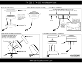
6-series speaker system is supplied with three different tweeter mounting options. Surface, flush
angled flush mount. After you have decided which option is best suited to your installation, refer
he following sections for specific details on mounting the tweeter.
ace mount
preparation of the mounting surface for the tweeter involves drilling three holes. Two holes are for
mounting screws. Their centers must be spaced 15/16” / 24mm apart. Use a 1/8" / 3mm drill bit
the supplied flat head #6 X 3/4: screws to mount the cup. The third 1/4” / 7mm hole is required
the wire to pass through.
the template provided to locate the hole centers. Cut carpeting or fabric away from the hole loca-
s to prevent tangling of fibers in the drill bit.
e: the orientation of the three holes determines the installed position of the tweeter.
a/d/s/ nameplate on the surface mount cup will end up closest to the wiring hole as shown.
ace mount cup mounting
t two #6 X 3/4" flat head sheet metal screws through
holes in the bottom of the surface mount cup. Screw the
in place. Be sure the mounting screws are driven in
ght, so the heads sit flush on the cup mounting surface.
ensures the tweeter will seat properly in the surface
unt cup.
h mount
ck the intended installation site to be sure that there is
cient depth behind the mounting surface for the rear
and mounting screws. The minimum depth required
nd the back of the mounting surface is 1” / 25mm.
front cup mounts into the mounting surface through a 1 7/8” / 48mm diameter hole. Be careful
the hole does not exceed 2 1/8” / 55mm diameter at any point so that the rim of the cup will com-
ely cover the edge of the hole.
the template provided to locate the hole centers. Cut carpeting or fabric away from the cutting
h to prevent tangling of fibers in the saw blade.
e: place enough washers over the protruding screws on the back of the front cup so that their com-
d thickness is somewhat less than the thickness of the mounting surface. This will insure adequate
nching” of the mounting cups without danger of breaking the rear cup.
h mount and angled flush mount cup mounting
t two #6 X 3/4" flat head sheet metal screws through the holes in the bottom of the flush mount
Hold the back the cup in place behind
hole cut in the panel and screw the front
into the back cup. Use care not to over-
ten the screws. Be sure the mounting
ws are driven in straight, so the heads sit
h on the cup mounting surface. This
es the tweeter will seat properly in the
h mount cup.
/