Olsen Item 64407-UPC 792363644075 Owner's manual
- Category
- Power tools
- Type
- Owner's manual
This manual is also suitable for

!"#"$%&'(%)*+#"$*%,$-%.$$/-00)))1.,(+&(2(*"3.$14&5
65,"7%&'(%$*4.8"4,7%#'//&($%,$-%/(&9'4$#'//&($:.,(+&(2(*"3.$14&5
Owner’s Manual & Safety Instructions
Save This Manual Keep this manual for the safety warnings and precautions, assembly,
operating, inspection, maintenance and cleaning procedures. Write the product’s serial number in the
back of the manual near the assembly diagram (or month and year of purchase if product has no number).
Keep this manual and the receipt in a safe and dry place for future reference. 20k
When unpacking, make sure that the product is intact
and undamaged. If any parts are missing or broken,
please call 1-888-866-5797 as soon as possible.
Copyright
©
2020 by Harbor Freight Tools
®
. All rights reserved.
No portion of this manual or any artwork contained herein may be reproduced in
any shape or form without the express written consent of Harbor Freight Tools.
Diagrams within this manual may not be drawn proportionally. Due to continuing
improvements, actual product may differ slightly from the product described herein.
Tools required for assembly an d se rv ic e may n ot b e in cl uded.
Read this material before using this product.
Failure to do so can result in serious injury.
SAVE THIS MANUAL.

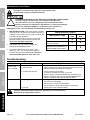
Page 2 ;&(%$*4.8"4,7%<'*#$"&8#=%/7*,#*%4,77%>?@@@?@AA?BCDC1 Item 64407
EF;6GH I6JKLMN OPGGLMN QFLMG6MFMO6E6GPR
G,+7*%&2%O&8$*8$#
Safety ........................................................................2
Specifications ............................................................6
Setup .........................................................................6
Welding .....................................................................10
Maintenance .............................................................18
Parts Lists and Assembly Diagrams .........................19
Warranty ...................................................................24
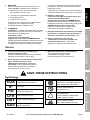
IFSMLMN%EHQTUJE%FMK%K6;LMLGLUME
This is the safety alert symbol. It is used to alert you to potential
personal injury hazards. Obey all safety messages that
follow this symbol to avoid possible injury or death.
Indicates a hazardous situation which, if not avoided,
will result in death or serious injury.
Indicates a hazardous situation which, if not avoided,
could result in death or serious injury.
Indicates a hazardous situation which, if not avoided,
could result in minor or moderate injury.
Addresses practices not related to personal injury.
LQRUSGFMG%EF;6GH%LMEGSPOGLUME
S*,9%,77%#,2*$V%),(8"83#%,89%"8#$('4$"&8#1%%
Failure to follow the warnings and instructions may result in electric shock, fire and/or serious injury.
E,W*%,77%),(8"83#%,89%"8#$('4$"&8#%2&(%2'$'(*%(*2*(*84*1
The warnings, precautions, and instructions discussed in this instruction manual
cannot cover all possible conditions and situations that may occur.
It must be understood by the operator that common sense and caution are factors which
cannot be built into this product, but must be supplied by the operator.
I&(X%F(*,%E,2*$V
1. Y**/%V&'(%)&(X%,(*,%47*,8%,89%)*77%7"$1
Cluttered benches and dark areas invite accidents.
2. Y**/%+V#$,89*(#=%4."79(*8=%,89%W"#"$&(#%,),V%
)."7*%&/*(,$"831 Distractions can cause you to
lose control. Protect others in the work area from
intense heat. Do not allow others close enough to
look at the flame as eye damage is a real possibility.
Provide barriers or shields as needed.
3. I.*8%/&##"+7*=%5&W*%$.*%)&(X%$&%,%7&4,$"&8%)*77%
,),V%2(&5%4&5+'#$"+7*%5,$*(",7#1 If relocation
is NOT possible, protect the combustibles with a
cover made of fire resistant material. Remove or
make safe all combustible materials for a radius
of 35 feet (10 meters) around the work area.
4. 6847&#*%$.*%)&(X%,(*,%)"$.%/&($,+7*%2"(*%
(*#"#$,8$%#4(**8#1 Use a fire resistant
material to block all openings and protect
combustible walls, ceilings, floors, etc.
5. L2%)&(X"83%8*,(0&8%,%5*$,7%),77=%4*"7"83=%27&&(=%
*$41=%/(*W*8$%"38"$"&8%&2%4&5+'#$"+7*#%&8%
$.*%&$.*(%#"9*%+V%5&W"83%$.*%4&5+'#$"+7*#%
$&%,%#,2*%7&4,$"&81
If relocation of combustibles is NOT possible,
designate someone to act as a fire watch equipped
with a fire extinguisher during the welding or
cutting process and for at least one half hour after
the welding or cutting project is completed.
6. K&%8&$%/7,4*%$.*%G&(4.%&8%,8V%5,$*(",7%&$.*(%
$.,8%+,(*%4&84(*$*%'8$"7%"$%.,#%4&&7*9%4&5/7*$*7V1

Page 3;&(%$*4.8"4,7%<'*#$"&8#=%/7*,#*%4,77%>?@@@?@AA?BCDC1Item 64407
EF;6GHI6JKLMNOPGGLMNQFLMG6MFMO6 E6GPR
7. K&%8&$%)*79%&(%4'$%,8V%5,$*(",7%$.,$%.,#%,%
4&5+'#$"+7*%4&,$"83%&(%,%4&5+'#$"+7*%"8$*(8,7%
#$('4$'(*=%#'4.%,#%9('5#%&(%$,8X#=%)"$.&'$%,8%
,//(&W*9%5*$.&9%2&(%*7"5"8,$"83%$.*%.,Z,(91
8. K&%8&$%9"#/&#*%&2%.&$%#7,3%"8%4&8$,"8*(#%
.&79"83%4&5+'#$"+7*%5,$*(",7#1
9. Y**/%,%2'77V%4.,(3*9%2"(*%*[$"83'"#.*(%47&#*%
+V%,89%X8&)%$.*%/(&/*(%),V%$&%'#*%"$1
10. F2$*(%)*79"83%&(%4'$$"83%5,X*%,%$.&(&'3.%
4.*4X%2&(%*W"9*84*%&2%2"(*%,89%+*%,),(*%$.*%
*,#"7V%W"#"+7*%27,5*%&(%#5&X*%5,V%8&$%+*%
/(*#*8$%2&(%#&5*%$"5*%,2$*(%,%2"(*%.,#%#$,($*91
11. K&%8&$%)*79%&(%4'$%"8%,$5&#/.*(*#%
4&8$,"8"83%9,83*(&'#7V%(*,4$"W*%&(%
27,55,+7*%3,#*#=%W,/&(#=%7"<'"9#=%&(%9'#$1
12. O7*,8%,89%/'(3*%4&8$,"8*(#%+*2&(*%,//7V"83%
.*,$1 Do not apply heat to a container that has
held an unknown substance or a combustible
material whose contents, when heated, can
produce flammable or explosive vapors.
Vent closed containers, including castings,
before preheating, cutting, or welding.
R*(#&8,7%E,2*$V
1. I*,("83%,89%'#"83%/*(#&8,7%#,2*$V%47&$."83%,89%
#,2*$V%9*W"4*#%(*9'4*%$.*%("#X%&2%"8\'(V1%%%
I*,(%$.*%2&77&)"83-
a. ;"(*?(*#"#$,8$%47&$."83 (Do not wear pants with
cuffs, shirts with open pockets, or any clothing
that can catch and hold molten metal or sparks.)
b. ;"(*?(*#"#$,8$%7*,$.*(%7*33"83#%,89%)&(X%+&&$#
c. K(V=%"8#'7,$"83%7*,$.*(%)*79"83%37&W*#
d. MLUE]?,//(&W*9%(*#/"(,$&(
e. E.,9*%B%&(%."3.*(%)*79"83%3&337*#
f. F//(&/(",$*%.*,9%4&W*("83%$&%
/(&$*4$%.*,9%,89%8*4X
g. ;"(*?(*#"#$,8$%*,(%/7'3#%&(%*,(%5'22#%
^"2%)*79"83%&(%4'$$"83%&W*(.*,9%
&(%"8%4&82"8*9%#/,4*#_
Keep clothing and safety equipment free of grease,
oil, solvents and any other flammable substances.
2. E$,V%,7*($1%%I,$4.%).,$%V&'%,(*%9&"83=%,89%
'#*%4&55&8%#*8#*%).*8%&/*(,$"83%$."#%G&(4.1%%%
K&%8&$%'#*%)."7*%$"(*9%&(%'89*(%$.*%
"827'*84*%&2%9('3#=%,74&.&7=%&(%5*9"4,$"&81
A moment of inattention while operating
may result in serious personal injury.
3. K&%8&$%&W*((*,4.1%%Y**/%/(&/*(%2&&$"83%,89%
+,7,84*%,$%,77%$"5*#1% Proper footing and balance
enables better control in unexpected situations.
4. LM]FJFGLUM%]F`FSK-%
I*79"83%,89%O'$$"83%R(&9'4*%
GUaLO%;PQ6E1
Exposure to welding or cutting exhaust
fumes can increase the risk of developing certain
cancers, such as cancer of the larynx and lung
cancer. Also, some diseases that may be linked to
exposure to welding or cutting exhaust fumes are:
• Early onset of Parkinson’s Disease
• Heart disease • Ulcers
• Damage to the reproductive organs
• Inflammation of the small intestine or stomach
• Kidney damage
• Respiratory diseases such as
emphysema, bronchitis, or pneumonia
Use natural or forced air ventilation and
wear a respirator approved by NIOSH
to protect against the fumes produced
to reduce the risk of developing the
above illnesses.
5. FW&"9%&W*(*[/&#'(*%$&%2'5*#%,89%3,#*#1
Keep your head out of the fumes. Do not breathe
fumes. Use enough ventilation or exhaust,
or both to keep fumes and gases away from your
breathing area. Where ventilation is questionable,
have a qualified technician take an air sampling
to determine the need for corrective measures.
If necessary, use mechanical ventilation to
improve air quality. If this is not possible, use an
approved respirator. Do not work in confined
areas unless they are well-ventilated or you are
wearing an air supplied ventilator. Always follow
OSHA guidelines for Permissible Exposure Limits
(PEL’s) for various fumes and gases.
Follow the American Conference of Governmental
Industrial Hygienists recommendations for the
Threshold Limit Values (TLV’s) for fumes and gases.
Have a recognized specialist in Industrial Hygiene
or Environmental Services check the operation
and air quality and make recommendations
for the specific welding or cutting situation.

Page 4 ;&(%$*4.8"4,7%<'*#$"&8#=%/7*,#*%4,77%>?@@@?@AA?BCDC1 Item 64407
EF;6GH I6JKLMN OPGGLMN QFLMG6MFMO6E6GPR
6<'"/5*8$%E*$'/%E,2*$V
1. Q,X*%#'(*%V&'%,(*%/(*/,(*9%$&%+*3"8%
)&(X%+*2&(*%&/*8"83%3,#%#'//7V1
2. G&%/(*W*8$%*[/7&#"&8=%'#*%(*W*(#*?27&)%
4.*4X%W,7W*#%,89%27,#.+,4X%,((*#$&(#%
^#&79%#*/,(,$*7V_%&8%$.*%+,#*%&2%$.*%G&(4.1
3. P#*%)"$.%&[V3*8%,89%,4*$V7*8*%&87V1
Do not modify this torch or use it for a
purpose for which it is not intended.
4. E*$%F4*$V7*8*%S*3'7,$&(%8&%3(*,$*(%$.,8%>B%REL1
Acetylene is unstable and can
explode if over-pressurized.
5. K&%8&$%'#*%&"7=%3(*,#*%&(%
$.(*,9%#*,7%$,/*%&8%,8V%4&88*4$&(1
6. P#*%47,5/#%^8&$%"847'9*9_%&(%&$.*(%/(,4$"4,7%
),V#%$&%#*4'(*%,89%#'//&($%$.*%)&(X/"*4*%
$&%,%#$,+7*%/7,$2&(51 Holding the work by hand
or against your body is unstable and may lead
to loss of control, fire and/or personal injury.
7. P#*%&87V%,44*##&("*#%$.,$%,(*%(*4&55*89*9%
+V%$.*%5,8'2,4$'(*(%2&(%V&'(%5&9*7%G&(4.1
Accessories that may be suitable for one Torch may
become hazardous when used on another Torch.
Only use proper gas hoses.
OV7"89*(%E,2*$V
1. K&%8&$%'#*%9*8$*9%&(%9,5,3*9%4V7"89*(#1
2. E*4'(*%4V7"89*(#%$&%,%4,($=%),77=%&(%/&#$%$&%
/(*W*8$%$.*5%2(&5%2,77"831
Use and store cylinders in an upright position only.
3. P#*%4V7"89*(%4,/#%).*8%5&W"83%
&(%#$&("83%4V7"89*(#1
4. K&%8&$%#$&(*%4V7"89*(#%"8%
$*5/*(,$'(*#%>bcd%;%&(%."3.*(1
5. 6QRGH%OHJLMK6SE-%
KU%MUG%KSUR=%EGSLY6=%RPMOGPS6=%]6FG%US%
E6G%;LS6%GU%F%OHJLMK6S=%6!6M%L;%LG%LE%6QRGH1%%%
Keep empty cylinders in specified areas
and clearly mark “empty.” Contact local
solid waste authorities for instructions on correct
disposal or recycling of empty cylinders.
6. Y66R%IS6MO]%UM%
FO6GHJ6M6%OHJLMK6SeE%!FJ!6%
).*8*W*(%4V7"89*(%"#%"8%'#*%$&%,77&)%
<'"4X%#.'$&22%"8%4,#*%&2%*5*(3*84V1
6<'"/5*8$%L8#/*4$"&8
1. KU%MUG%PE6%;JFQ6%GU%K6G6OG%J6FYE1
2. LMER6OG%T6;US6%6!6SH%PE61%%%
J&&X%2&(%$.*%2&77&)"83=%,89%9&%8&$%
'#*%X"$%"2%,8V%9,5,3*%"#%8&$*9-
a. L8#/*4$%$.*%$,/*(*9%#*,$"83%#'(2,4*#%&8%$.*%
M&ZZ7*#%,89%$.*%G"/%M'$1 Have a qualified
technician resurface the seat area if it has
dents, burrs, or is burned. A poor seating
surface may result in backfire or flashback.
b. 6[,5"8*%,77%.&#*#%2&(%4'$#=%4(,4X#=%
+'(8#=%)&(8%,(*,#=%&(%&$.*(%9,5,3*1
Do not use if damaged.
c. O.*4X%2&(%7&&#*%4&88*4$"&8#%
'#"83%#&,/V%),$*(%#&7'$"&81
Tighten or repair any leaks found.
d. K&%8&$%'#*%$.*%G&(4.%Y"$%"2%*"$.*(%
3,#%9&*#%8&$%$'(8%&22%4&5/7*$*7V%
).*8%$.*%U[V3*8%G&(4.%!,7W*%,89%
F4*$V7*8*%G&(4.%!,7W*%,(*%47&#*91 Leakage
of gas from the tip is a substantial safety risk.
If gas cannot be turned off at the Torch Handle,
it is dangerous and must be replaced.
e. L8#/*4$%2&(%,8V%&$.*(%9*2*4$#%&(%9,5,3*1
Do not use any damaged parts.
Tag damaged parts “Do not use” until repaired.
U/*(,$"&8%E,2*$V
1. L8#/*4$%+*2&(*%*W*(V%'#*f%
#**%/(*W"&'#%),(8"83%#*4$"&81
2. P#*%&87V%)"$.%/(&/*(%W*8$"7,$"&81
3. K&%8&$%$&'4.%)&(X/"*4*%&(%$"/%'8$"7%4&&71
4. Y**/%.&#*#%,),V%2(&5%.&$%/,($#=%2(&5%
)*7904'$%,(*,=%,89%2(&5%27,5*1
5. M*W*(%7*,W*%$.*%G&(4.%'8,$$*89*9%).*8%
"$%"#%,$$,4.*9%$&%,%3,#%#'//7V1
6. F77&)%#'22"4"*8$%$"5*%2&(%$.*%G&(4.%$&%
4&5/7*$*7V%4&&7%+*2&(*%#$&("831
7. F8V%5,$*(",7%9"#4.,(3*9%2(&5%$.*%)&(X%,(*,%
9'("83%'#*%)"77%+*%*[$(*5*7V%.&$1 Use care to
not get burned by slag or other waste products.

Page 5;&(%$*4.8"4,7%<'*#$"&8#=%/7*,#*%4,77%>?@@@?@AA?BCDC1Item 64407
EF;6GHI6JKLMNOPGGLMNQFLMG6MFMO6 E6GPR
8. TFOY;LS6-%%%
When the flame goes out with a loud “pop,” it is
called a +,4X2"(*1 Backfire can be caused by:
a. Operating the Torch at lower pressures
than required for the Tip used.
b. Touching the Tip against the workpiece.
c. Overheating the Tip.
d. An obstruction in the Tip.
If backfire occurs, close the Torch Handle Valves
(oxygen first, then acetylene) and after
remedying the cause, relight the torch.
9. ;JFE]TFOY-%%%
;7,#.+,4X%is a condition that results when the flame
flashes back into the Torch and burns inside with a
shrill hissing or squealing noise.
L2%27,#.+,4X%&44'(#=%
47&#*%$.*%G&(4.%],897*%!,7W*#%
^&[V3*8%2"(#$=%$.*8%,4*$V7*8*_%LQQ6KLFG6JHg
Flashback generally indicates a problem that should
be repaired before proceeding with the job at hand.
A clogged Tip, improper functioning of the Valves,
or incorrect acetylene/oxygen pressure could lead
to flashback. Find and correct the cause before
relighting the Torch.
If the cause is not found, have the kit serviced by a
qualified technician before returning to your project.
10. T*),(*%&2%7*,X"83%3,#1%%%
L2%V&'%8&$"4*%$.*%&9&(%&2%,4*$V7*8*%9'("83%'#*=%%
47&#*%$.*%G&(4.%],897*%!,7W*#%
^&[V3*8%2"(#$=%$.*8%,4*$V7*8*_%LQQ6KLFG6JHg%
Extinguish all open flames and carefully check all
hoses and connections for leaks using soapy water.
M6!6S%4.*4X%2&(%7*,X#%'#"83%,%27,5*1
If the odor continues do not use the Torch.
Call acetylene supplier for assistance.
11. S*,9%,89%'89*(#$,89%,77%"8#$('4$"&8#%,89%#,2*$V%
/(*4,'$"&8#%,#%&'$7"8*9%"8%$.*%5,8'2,4$'(*(e#%
5,8',7%2&(%$.*%5,$*(",7%V&'%)"77%)*79%&(%4'$1
12. F2$*(%'#*=%+7**9%7"8*#%,89%#$&(*%,77%
4&5/&8*8$#%&'$%&2%(*,4.%&2%4."79(*8%,89%
&$.*(%'8$(,"8*9%/*(#&8#1 Torches are
dangerous in the hands of untrained users.
E*(W"4*
1. G&(4.%#*(W"4*%5'#$%+*%/*(2&(5*9%&87V%+V%
<',7"2"*9%(*/,"(%/*(#&88*71
Service or maintenance performed by unqualified
personnel could result in a risk of injury.
2. I.*8%#*(W"4"83=%'#*%&87V%"9*8$"4,7%(*/7,4*5*8$%
/,($#1%%;&77&)%"8#$('4$"&8#%"8%$.*%%
“Maintenance Instructions” #*4$"&8%&2%
$."#%5,8',71% Use of unauthorized parts or
failure to follow maintenance instructions
may create a risk of fire or injury.
3. Q,"8$,"8%/(&9'4$%7,+*7#%,89%8,5*/7,$*#1
These carry important information.
If unreadable or missing, contact
Harbor Freight Tools for a replacement.
%EF!6%G]6E6%LMEGSPOGLUME1
EV5+&7&3V
ONF
Compressed Gas Association
2$
h
Cubic Feet
REL
Pounds per Square Inch
O;]
Cubic Feet per Hour flow
UaH
Oxygen related components
NFE
Fuel gas (acetylene)
related components
WARNING marking concerning Risk
of Eye Injury. Wear ANSI-approved
safety goggles with side shields.
Read the manual before
set-up and/or use.
WARNING marking concerning
Risk of Explosion.
Do not use flame to detect leaks.
Handle cylinders properly.
WARNING marking concerning
Risk of Inhalation Hazard.
Use in well-ventilated area only.

Page 6 ;&(%$*4.8"4,7%<'*#$"&8#=%/7*,#*%4,77%>?@@@?@AA?BCDC1 Item 64407
EF;6GH I6JKLMN OPGGLMN QFLMG6MFMO6E6GPR
E/*4"2"4,$"&8#
Welding
Nozzle
VH-W2, Size 2, welds up to 1/8"
Cutting Tip 1-101, Size 1, cuts up to 3/4"
Cutting Tip
Replacement
Victor Style
Regulators Oxygen: CGA 540 – Acetylene: CGA 510
Hose type
15 ft. L x 1/4" inside diameter
Color Coded Twin Hose
Green oxygen hose w/right-hand fitting threads
Red acetylene hose w/left-hand fitting threads
Accessories Shaded Goggles, Striker, Tip Cleaner
!"4$&(?E$V7*%G"/
E*$'/
% S*,9%$.*%6MGLS6%LQRUSGFMG%EF;6GH%LM;USQFGLUM%#*4$"&8%,$%$.*%+*3"88"83%&2%$."#%
5,8',7%"847'9"83%,77%$*[$%'89*(%#'+.*,9"83#%$.*(*"8%+*2&(*%#*$%'/%&(%'#*%&2%$."#%/(&9'4$1
I&(X/"*4*%,89%I&(X%F(*,%E*$'/
1. Designate a work area that is clean and well-lit.
The work area must not allow access by children
or pets to prevent distraction and injury.
2. Remove all combustible material from area and/
or cover surfaces with fire resistant material.
3. The work area must have a fireproof floor.
4. Secure loose workpieces using a vise or clamps
(not included) to prevent movement while working.
M&$*- Proper weld preparation can be complicated,
and is outside the scope of this manual.
G&&7%E*$%P/%>%&2%h%?%F##*5+7V
% S*,9%$.*%6MGLS6%LQRUSGFMG%EF;6GH%LM;USQFGLUM%#*4$"&8%,$%$.*%+*3"88"83%&2%$."#%
5,8',7%"847'9"83%,77%$*[$%'89*(%#'+.*,9"83#%$.*(*"8%+*2&(*%#*$%'/%&(%'#*%&2%$."#%/(&9'4$1
GU%RS6!6MG%E6SLUPE%LMiPSH%;SUQ%6aRJUELUM-%
G'(8%$.*%U[V3*8%,89%F4*$V7*8*%G&(4.%!,7W*#%2'77V%47&4X)"#*%$&%47&#*%
^&[V3*8%2"(#$%,89%,4*$V7*8*%#*4&89_%+*2&(*%5,X"83%,8V%,9\'#$5*8$#%&(%%
/*(2&(5"83%,8V%"8#/*4$"&8%&(%#*(W"4*%$&%$."#%/(&9'4$1
M&$*- For additional information regarding the parts listed in the following pages, refer to the Assembly Diagrams
near the end of this manual. All instructions in this manual are 2&(%&[V3*8%,89%,4*$V7*8*%3,#%&87V.
1. Secure cylinders to a cart, wall, or post to
prevent them from falling. K&%8&$%/7,4*%
F4*$V7*8*%OV7"89*(%&8%"$#%#"9*1
IFSMLMNg%GU%RS6!6MG%;LS6%FMK%6aRJUELUM-%%
Q,X*%#'(*%$.*(*%"#%8&%&"7=%3(*,#*=%&(%"38"$"&8%
#&'(4*%^#'4.%,#%,%.&$%)*79=%*7*4$("4%5&$&(=%
&(%,8&$.*(%)*79"83%&/*(,$"&8_%8*,(+V%
+*2&(*%/(&4**9"83%)"$.%$.*%8*[$%#$*/1
2. While standing to one side, “crack” each cylinder
valve. “Cracking” is to quickly open and close the
valve, allowing a small amount of gas to escape and
clearing the valve of any foreign material.
IFSMLMNg%%GU%RS6!6MG%E6SLUPE%LMiPSH- L2%
&"7%&(%3(*,#*%"#%2&'89=%9"#4&8$"8'*%'#"83%4V7"89*(%
,89%"55*9",$*7V%4&8$,4$%V&'(%3,#%#'//7"*(1
3. Attach the Green labeled Oxygen Regulator
to the Oxygen Cylinder and the
green oxygen hose to the Regulator.
4. Attach the Red labeled Acetylene Regulator to
the Acetylene Cylinder and the red acetylene
hose to the Regulator, $"3.$*8%4&'8$*(47&4X)"#*%
?%$.(*,9#%,(*%(*W*(#*9.
T("*27V%&/*8%W,7W*%$&%47*,8=%%
$.*8%47&#*%W,7W*1
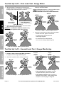
F##*5+7V%E$*/%b-%%O(,4X%6,4.%OV7"89*(%!,7W*

Page 7;&(%$*4.8"4,7%<'*#$"&8#=%/7*,#*%4,77%>?@@@?@AA?BCDC1Item 64407
EF;6GHI6JKLMNOPGGLMNQFLMG6MFMO6 E6GPR
5. G&(4.%],897*%E*$'/-
a. Remove the inlet covers.
b. Make sure both Check Valves are
in place on the Torch Handle.
c. Connect the green-oxygen hose to the
oxygen Check Valve on the Torch Handle.
d. Connect the red-acetylene hose to the acetylene
Check Valve on the Torch Handle,
$"3.$*8%4&'8$*(47&4X)"#*%?%
$.(*,9#%,(*%(*W*(#*9.
O.*4X%
!,7W*%^Ua_
U[V3*8%
]&#*%
^3(**8_
O.*4X%!,7W*%^FO_
F4*$V7*8*%]&#*%^(*9_
G&(4.%
],897*
F##*5+7V%E$*/%B-%%G&(4.%],897*%E*$'/
6. I*79"83%M&ZZ7*%E*$'/-
Connect the Welding Nozzle
to the Torch Handle.
I*79"83%M&ZZ7*
G&(4.%],897*
F##*5+7V%E$*/%A-%%I*79"83%E*$'/
6a. O'$$"83%F$$,4.5*8$%E*$'/-
IFSMLMNg%%GU%RS6!6MG%E6SLUPE%LMiPSH-%
T6;US6%OUMM6OGLMN=%%
5,X*%#'(*%$.*%$)&%
U?S"83#%&8%$.*%*89%&2%$.*%
O'$$"83%F$$,4.5*8$%,(*%
8&$%9,5,3*9%&(%5"##"83=%
&$.*()"#*%3,#*#%)"77%5"[%
"8#"9*%$.*%G&(4.%],897*%
,89%(*#'7$%"8%27,#.+,4X%
&(%+,4X2"(*#1
Connect the Cutting Attachment to the Torch Handle.
Then, connect the Cutting Tip to the Cutting Attachment.
O'$$"83%
F$$,4.5*8$
G&(4.%
],897*
O'$$"83%G"/
F##*5+7V%E$*/%A,-%%O'$$"83%E*$'/
7. T*2&(*%&/*(,$"&8=%$.*%7*,X%$*#$#%&8%$.*%
2&77&)"83%/,3*#%5'#$%+*%9&8*%,2$*(%4&88*4$"&8%
$&%4.*4X%2&(%7*,X#%"8%$.*%#V#$*51
O'$$"83%
F$$,4.5*8$
U?S"83#

Page 8 ;&(%$*4.8"4,7%<'*#$"&8#=%/7*,#*%4,77%>?@@@?@AA?BCDC1 Item 64407
EF;6GH I6JKLMN OPGGLMN QFLMG6MFMO6E6GPR
G&&7%E*$%P/%b%&2%h%?%;"(#$%J*,X%G*#$-%%E&,/V%I,$*(
G."#%$*#$%9*$*4$#%5,\&(%7*,X#1
1. After everything is connected, close both Torch
Handle Valves, turning clockwise. Close Regulators,
turning knobs counterclockwise until loose.
O7&#*%!,7W*#
^G'(8%47&4X)"#*1_
O7&#*%S*3'7,$&(#
^G'(8%4&'8$*(47&4X)"#*%'8$"7%7&&#*1_
J*,X%G*#$%>%E$*/%>%
2. Open the cylinder valves turning counterclockwise
only until the gas starts flowing.
1
IFSMLMNg%GU%RS6!6MG%E6SLUPE%LMiPSH-%U87V%
&/*8%F4*$V7*8*%OV7"89*(%!,7W*%>0j%$&%>0b%$'(81
F4*$V7*8*%
OV7"89*(
U[V3*8%
OV7"89*(
J*,X%G*#$%>%E$*/%b-%%U/*8%OV7"89*(%!,7W*#
3. Open the U[V3*8%cylinder valve completely,
turning it counterclockwise.
F9\'#$ the U[V3*8 Regulator to deliver bc%REL. Adjust
the F4*$V7*8* Regulator to deliver >c%REL.
KU%MUG%6aO66K%>B%REL%FO6GHJ6M6%RS6EEPS61
F4*$V7*8*%
S*3'7,$&(
>c%REL
U[V3*8%
S*3'7,$&(
bc%REL
J*,X%G*#$%>%E$*/%h-%%E*$%G*#$"83%R(*##'(*#
4. Check all connections for leaks using soapy water:
• If leaks are found, tighten connections.
• If a leak persists, discontinue use
and call gas supplier.
• If no leaks are found with this test,
move on to the Gauge Monitoring test.
G&&7%E*$%P/%h%&2%h%?%E*4&89%J*,X%G*#$-%%N,'3*%Q&8"$&("83
G."#%$*#$%9*$*4$#%5"8&(%7*,X#1
1. ;&77&)%,77%#$*/#%"8%$.*%E&,/V%I,$*(%$*#$%,+&W*%
to prepare for the Gauge Monitoring test.
2. Close both cylinder valves, turning clockwise.
F4*$V7*8*%
OV7"89*(
U[V3*8%
OV7"89*(
J*,X%G*#$%b%E$*/%b-%%O7&#*%OV7"89*(%!,7W*#
3. Monitor gauges on both Regulators for five minutes.
F4*$V7*8*F4*$V7*8*%
S*3'7,$&(
F4*$V7*8*%F4*$V7*8*%
K*7"W*(V%K*7"W*(V%
R(*##'(*R(*##'(*
F4*$V7*8*%F4*$V7*8*%
OV7"89*(%OV7"89*(%
R(*##'(*R(*##'(*
U[V3*8%
S*3'7,$&(
U[V3*8%U[V3*8%
K*7"W*(V%K*7"W*(V%
R(*##'(*R(*##'(*
U[V3*8%U[V3*8%
OV7"89*(%OV7"89*(%
R(*##'(*R(*##'(*
J*,X%G*#$%b%E$*/%h-%%Q&8"$&(%N,'3*#
k% L2%$.*%(*,9"83#%9&%8&$%4.,83*, the test is
completed and the system has no leaks.
k% L2%,8V%(*,9"83%4.,83*#, there is a leak on
that side of the system. Follow Gauge Leak
Analysis on the next page to diagnose.

Page 9;&(%$*4.8"4,7%<'*#$"&8#=%/7*,#*%4,77%>?@@@?@AA?BCDC1Item 64407
EF;6GHI6JKLMNOPGGLMNQFLMG6MFMO6 E6GPR
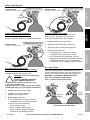
N,'3*%J*,X%F8,7V#"#
L2%3,'3*#%5&W*%,#%#.&)8
7*,X%
"8#"9*%
S*3'7,$&(
U[V3*8%#.&)81%%%
^R(&4*9'(*%,7#&%,//7"*#%$&%,4*$V7*8*1_
G]6M
L2%$.*%OV7"89*(%R(*##'(*%9*4(*,#*#%%
,89%$.*%K*7"W*(V%R(*##'(*%"84(*,#*#%-
There is a leak in the Regulator seat.
Have the Regulator repaired by a qualified technician.
7*,X%
+*2&(*%
S*3'7,$&(
L2%OV7"89*(%3,'3*%5&W*#%,#%#.&)8=%
,89%K*7"W*(V%3,'3*%#$,V#%#$"77
U[V3*8%#.&)81%%%
^R(&4*9'(*%,7#&%,//7"*#%$&%,4*$V7*8*1_
G]6M
L2%OV7"89*(%R(*##'(*%9*4(*,#*#%%
+'$%$.*%K*7"W*(V%R(*##'(*%(*5,"8#%4&8#$,8$%?
The leak is at cylinder valve or connection
between Regulator and cylinder valve.
KFMN6Sg%G&%/(*W*8$%#*("&'#%"8\'(V%
,89%K6FG]-%%
KU%MUG%GLN]G6M%US%FKiPEG%
FMH%OUMM6OGLUM%+*$)**8%
$.*%4V7"89*(%,89%4V7"89*(%W,7W*=%
&(%2&(4*%$.*%4V7"89*(%W,7W*1%%
L2%$.*%4V7"89*(%W,7W*%"#%7*,X"83=%5&W*%$.*%4V7"89*(%
&'$#"9*%,89%8&$"2V%V&'(%3,#%#'//7"*(%"55*9",$*7V1
1. Release pressure from the system.
2. Tighten the connection between
Regulator and cylinder valve.
3. Repeat Gauge Leak Test.
a. If the gauges do not change, the test is
completed and the system has no leaks.
b. If the connection still leaks try
with a different cylinder.
c. If the connection leaks with the
different cylinder, have the Regulator
examined by a qualified technician.
U[V3*8%#.&)81%%%
^R(&4*9'(*%,7#&%,//7"*#%$&%,4*$V7*8*1_
7*,X%,2$*(%
S*3'7,$&(
L2%K*7"W*(V%3,'3*%5&W*#%,#%#.&)8
G]6M
L2%K*7"W*(V%R(*##'(*%9*4(*,#*#%-
The leak is at the Regulator outlet connection,
within the hose, at the torch inlet connection
or at the Torch Valve on the Torch Handle.
1. Release pressure from the system.
2. Tighten the Regulator outlet connection.
3. Tighten the Torch Handle Inlet connection.
4. Repeat Gauge Leak Test.
a. If the gauges do not change, the test is
completed and the system has no leaks.
b. If the connections are still leaking, have the
Regulator, Torch Handle, and hoses examined by
a qualified technician. If the hoses are leaking,
replace them, do not attempt to repair the hoses.
M&%J*,X#%;&'89
If the leak testing has been completed and the unit is
found to be working properly, open the cylinder valves,
turning counterclockwise, and proceed to operation.
IFSMLMNg%%GU%RS6!6MG%E6SLUPE%LMiPSH-%
U87V%&/*8%F4*$V7*8*%OV7"89*(%!,7W*%
>0j%$&%>0b%$'(8%$&%,77&)%<'"4X%#.'$&221
F4*$V7*8*%
OV7"89*(
U[V3*8%
OV7"89*(
U/*8%OV7"89*(%!,7W*#%U87V%F2$*(%G*#$"83%
O&82"(5#%G.*(*%F(*%M&%J*,X#

Page 10 ;&(%$*4.8"4,7%<'*#$"&8#=%/7*,#*%4,77%>?@@@?@AA?BCDC1 Item 64407
EF;6GH I6JKLMN OPGGLMN QFLMG6MFMO6E6GPR
I*79"83
I*79"83%G"/%R(*##'(*%E*$$"83#
This Torch Handle is capable of welding metals from 1/32″ up to 1-1/4″ thick.
The included Welding Nozzle, size 2, will weld metals up to 1/8″ thick.
Check the thickness of the metals to be welded and use the chart below to choose the size nozzle for the job.
If welding metals other than 1/32″ to 1/8″ thick, a different welding nozzle will be needed.
M&$*- Welding the thicker metals noted below will require special techniques,
such as edge chamfering, that are outside the scope of this manual.
G,+7*%F-%%I*79"83%M&ZZ7*%;7&)%K,$,
Metal
Thickness
(inches)
Nozzle
Size
Tip Orifice
Diameter
(inches)
Oxygen
Pressure
(PSI)
Acetylene
Pressure
(PSI)
Acetylene
(CFH)
1/32 000 0.024 3~5 3~5 1~2
3/64 00 0.028 3~5 3~5 1.5~3
1/16 0 0.031 3~5 3~5 1.7~3.4
5/64 1 0.035 3~5 3~5 2~4
3/32 2 0.039 3~5 3~5 3~6
1/8 3 0.051 3~6 3~6 5~10.5
1/4 4 0.067 4~6 4~6 8.5~19
3/8 5 0.079 5~7 5~7 11.5~26
1/2 6 0.091 6~8 5~8 15~35
1-1/4 7 0.126 8~10 8~10 30~60
G&(4.%
],897*
I*79"83%
M&ZZ7*
F4*$V7*8*%^NFE_
G&(4.%!,7W*
U[V3*8%^UaH_
G&(4.%!,7W*

Page 11;&(%$*4.8"4,7%<'*#$"&8#=%/7*,#*%4,77%>?@@@?@AA?BCDC1Item 64407
EF;6GHI6JKLMNOPGGLMNQFLMG6MFMO6 E6GPR
I*79"83%L8#$('4$"&8#
S*,9%$.*%6MGLS6%LQRUSGFMG%EF;6GH%LM;USQFGLUM%#*4$"&8%,$%$.*%+*3"88"83%&2%$."#%5,8',7%
"847'9"83%,77%$*[$%'89*(%#'+.*,9"83#%$.*(*"8%+*2&(*%#*$%'/%&(%'#*%&2%$."#%/(&9'4$1
L8#/*4$%$&&7%+*2&(*%'#*=%7&&X"83%2&(%7*,X"83=%9,5,3*9=%7&&#*=%,89%5"##"83%/,($#1%%%
L2%,8V%/(&+7*5#%,(*%2&'89=%9&%8&$%'#*%$&&7%'8$"7%(*/,"(*91
1. Set up for welding according to
instructions on pages 6-9.
2. Close both valves on the Torch Handle securely.
F4*$V7*8*%^NFE_
G&(4.%!,7W*
U[V3*8%^UaH_
G&(4.%!,7W*
I*79"83%E$*/%b-%%O7&#*%!,7W*#
3. Adjust the Acetylene and Oxygen Regulators to
their proper working pressures. See Table A on
page 10. %%
KU%MUG%6aO66K%>B%REL%
FO6GHJ6M6%RS6EEPS61
F4*$V7*8*F4*$V7*8*%
S*3'7,$&(
F4*$V7*8*%K*7"W*(V%R(*##'(*
KU%MUG%6aO66K%>B%REL1
U[V3*8%
S*3'7,$&(
U[V3*8%K*7"W*(V%U[V3*8%K*7"W*(V%
R(*##'(*R(*##'(*
I*79"83%E$*/%h-%%E*$%I*79"83%R(*##'(*#
E**%G,+7*%F%&8%/,3*%>c1
4. Hold the Torch Handle in one hand
and the Striker in the other hand.

Page 12 ;&(%$*4.8"4,7%<'*#$"&8#=%/7*,#*%4,77%>?@@@?@AA?BCDC1 Item 64407
EF;6GH I6JKLMN OPGGLMN QFLMG6MFMO6E6GPR
5. Open the Acetylene Torch Valve about 1/4 turn,
and quickly ignite the acetylene gas
coming out of the Nozzle by squeezing the
handle of the striker, creating a spark.
IFSMLMNg%%GU%RS6!6MG%E6SLUPE%LMiPSH- Do
not use matches or a butane lighter to light the Torch.
>0j%$'(8
F4*$V7*8*%^NFE_%
G&(4.%!,7W*
E$("X*(
I*79"83%E$*/%B-%%J"3.$"83%F4*$V7*8*
6. Put the striker down on a fireproof surface.
Slowly open the Acetylene Torch Valve
farther until the flame feathers at its
edge slightly, as shown below.
I*79"83%E$*/%A-%%E7&)7V%U/*8%
F4*$V7*8*%G&(4.%!,7W*%P8$"7%;7,5*%;*,$.*(#
7. ;7,5*%F9\'#$5*8$-
,1% E$,($"83%$&%F99%U[V3*8-
Slowly open the Oxygen Torch Valve.
The flame will change to a carbonizing flame with
a blue/white inner core, a white halo surrounding
the core and a light orange flame as shown
in Welding Step 7 illustration, below left.
+1% R(&/*(%U[V3*8%Q"[-
Continue slowly opening the Oxygen Torch Valve
until the large light orange section of the flame
becomes nearly colorless and the center of the
flame has a white core with little or no halo.
G."#%"#%$.*%l8*'$(,7m%27,5*%
8**9*9%2&(%&/*(,$"&8 as shown in
Welding Step 7 illustration, below center.
41% G&&%Q'4.%U[V3*8-
If you open the Oxygen Torch Valve too far, the
large section of the flame will be bluish-orange
and the inner core will be small as shown
in Welding Step 7 illustration, below right.
Close the Oxygen Torch Valve slightly until you
achieve the flame described in step b above.
IFSMLMNg%%GU%RS6!6MG%E6SLUPE%LMiPSH-
Wear appropriate welding goggles.
8. After the flame is adjusted as explained
and illustrated, proceed with welding.
M&$*- Oxygen-acetylene welding is a
two-handed process:
one hand controls the torch,
while the other hand controls
a filler rod (sold separately).
Proper welding techniques and weld preparation
are outside the scope of this manual.
Welding books and classes are recommended
to teach proper methods and technique.
9. After welding, follow shutdown
instructions on facing page.
J"3.$%
U(,83*%
;7,5*
T7'"#.%
O&(*
I."$*%
F4*$V7*8*%
],7&
,1%E$,($"83%$&%F99%U[V3*8
M*,(7V%
O&7&(7*##%
;7,5*
T7'*?I."$*%
O&(*
J"$$7*%&(%
M&%],7&
+1%R(&/*(%U[V3*8%Q"[
T7'"#.?
U(,83*%
;7,5*
E5,77=%J*##%
T("3.$%O&(*
41%G&&%Q'4.%U[V3*8
I*79"83%E$*/%C-%%%I*79"83%;7,5*%F9\'#$5*8$
U/*8%U[V3*8%G&(4.%
!,7W*%E7"3.$7V
O7&#*%U[V3*8%G&(4.%
!,7W*%E7"3.$7V

Page 13;&(%$*4.8"4,7%<'*#$"&8#=%/7*,#*%4,77%>?@@@?@AA?BCDC1Item 64407
EF;6GHI6JKLMNOPGGLMNQFLMG6MFMO6 E6GPR
I*79"83%E.'$9&)8%L8#$('4$"&8#
1. After work is complete,
first close the Oxygen Torch Valve clockwise,
then close the Acetylene Torch Valve clockwise.
b
>
E.'$9&)8%E$*/%>-%%O7&#*%G&(4.%!,7W*#
2. Fully close both cylinder valves, turning clockwise.
F4*$V7*8*%
OV7"89*(
U[V3*8%
OV7"89*(
E.'$9&)8%E$*/%b-%%O7&#*%OV7"89*(%!,7W*#
3. Open the Acetylene Torch Valve counterclockwise
to allow all the pressure to bleed out.
M&$*- If the tank gauge still has pressure,
the Acetylene Regulator needs to be opened.
F4*$V7*8*%^NFE_
G&(4.%!,7W*
T7**9%/(*##'(*%&8%
+&$.%3,'3*#%$&%c
E.'$9&)8%E$*/%h-%%U/*8%F4*$V7*8*%!,7W*
4. Open the Oxygen Torch Valve counterclockwise
to allow all the pressure to bleed out.
M&$*- If the tank gauge still has pressure,
the Oxygen Regulator needs to be opened.
U[V3*8%^UaH_
G&(4.%!,7W*
T7**9%/(*##'(*%&8%
+&$.%3,'3*#%$&%c
E.'$9&)8%E$*/%j-%%U/*8%U[V3*8%!,7W*
5. After releasing pressure, turn the Acetylene
Pressure Adjusting Screw counterclockwise
and remove it from its Regulator.
Then, turn the Oxygen Pressure Adjusting Screw
counterclockwise and remove it from its Regulator.
LQRUSGFMGg Failure to release all pressure on
the Regulators may permanently damage them.
F4*$V7*8*F4*$V7*8*%
S*3'7,$&(
U[V3*8%
S*3'7,$&(
E.'$9&)8%E$*/%B-%%O7&#*%S*3'7,$&(#
^G'(8%4&'8$*(47&4X)"#*%,89%(*5&W*1_
6. Lastly, close the Acetylene Torch Valve clockwise,
and close the Oxygen Torch Valve clockwise.
b
>
E.'$9&)8%E$*/%A-%%O7&#*%G&(4.%!,7W*#

Page 14 ;&(%$*4.8"4,7%<'*#$"&8#=%/7*,#*%4,77%>?@@@?@AA?BCDC1 Item 64407
EF;6GH I6JKLMN OPGGLMN QFLMG6MFMO6E6GPR
O'$$"83
O'$$"83%G"/%R(*##'(*%E*$$"83#
The Cutting Attachment is used to cut metal up to 3″ thick.
The included tip, size 1, cuts metal up to 3/4″ thick.
Check the thickness of the metal to be cut and use the chart below to choose the appropriate size tip for the job.
If cutting metals over 3/4″ thick, a different tip will be needed.
G,+7*%T-%%O'$$"83%G"/%;7&)%K,$,
Cutting
Thickness
(inches)
Standard
Nozzle
Size
Cutting Oxygen
Pressure
(PSI)
Acetylene
Pressure
(PSI)
Speed
(IPM)
1/2 0 30~35 3~5 20~24
3/4 1 30~35 3~5 17~21
1-1/2 2 40~45 3~7 13~17
2-1/2 3 45~50 4~10 10~13
3 4 45~50 5~10 9~12
The Cutting Attachment is attached to the Torch Handle and a Cutting Tip
is attached to the end of the Cutting Attachment.
R(*?.*,$%U[V3*8%!,7W*- Adjusts pre-heat flame oxygen level.
U[V3*8%O'$$"83%J*W*(- Activates extra flow of oxygen for cutting.
O'$$"83%
F$$,4.5*8$
G&(4.%
],897*
O'$$"83%
G"/
U[V3*8%
O'$$"83%
J*W*(
R(*?.*,$%
U[V3*8%!,7W*
F4*$V7*8*%^NFE_%
G&(4.%!,7W*
U[V3*8%^UaH_%
G&(4.%!,7W*

Page 15;&(%$*4.8"4,7%<'*#$"&8#=%/7*,#*%4,77%>?@@@?@AA?BCDC1Item 64407
EF;6GHI6JKLMNOPGGLMNQFLMG6MFMO6 E6GPR
O'$$"83%L8#$('4$"&8#
S*,9%$.*%6MGLS6 LQRUSGFMG%EF;6GH%LM;USQFGLUM%#*4$"&8%,$%$.*%+*3"88"83%&2%$."#%5,8',7%
"847'9"83%,77%$*[$%'89*(%#'+.*,9"83#%$.*(*"8%+*2&(*%#*$%'/%&(%'#*%&2%$."#%/(&9'4$1
L8#/*4$%$&&7%+*2&(*%'#*=%7&&X"83%2&(%7*,X"83=%9,5,3*9=%7&&#*=%,89%5"##"83%/,($#1%%
L2%,8V%/(&+7*5#%,(*%2&'89=%9&%8&$%'#*%$&&7%'8$"7%(*/,"(*91
1. Set up for cutting according to
instructions on pages 6-9.
2. Close all valves on the Torch Handle
and Cutting Attachment securely.
R(*?.*,$%
U[V3*8%!,7W*
F4*$V7*8*%^NFE_%
G&(4.%!,7W*
U[V3*8%^UaH_%
G&(4.%!,7W*
O'$$"83%E$*/%b-%%%O7&#*%!,7W*#
3. Adjust the Acetylene and Oxygen Regulators to their
proper working pressures,
see Table B on page 14.
KU%MUG%6aO66K%>B%REL%
FO6GHJ6M6%RS6EEPS61
F4*$V7*8*
F4*$V7*8*
S*3'7,$&(
F4*$V7*8*%K*7"W*(V%R(*##'(*
KU%MUG%6aO66K%>B%REL1
U[V3*8%
S*3'7,$&(
U[V3*8%K*7"W*(V%
U[V3*8%K*7"W*(V%
R(*##'(*
R(*##'(*
O'$$"83%E$*/%h-%%E*$%O'$$"83%R(*##'(*#
E**%G,+7*%T%&8%/,3*%>j1
4. Hold the Torch Handle in one hand
and the striker in the other hand.
5. Open the Acetylene Torch Valve about 1/4 turn,
and quickly ignite the acetylene gas
coming out of the Nozzle by squeezing the
handle of the striker, creating a spark.
IFSMLMNg%%GU%RS6!6MG%E6SLUPE%LMiPSH- Do
not use matches or a butane lighter to light the Torch.
>0j%$'(8
F4*$V7*8*%^NFE_%
G&(4.%!,7W*
E$("X*(
O'$$"83%E$*/%B-%%J"3.$"83%F4*$V7*8*
6. Put the striker down on a fireproof surface.
Slowly open the Acetylene Torch Valve
farther until the flame feathers at its
edge slightly, as shown below.
O'$$"83%E$*/%A-%%E7&)7V%U/*8%
F4*$V7*8*%G&(4.%!,7W*%P8$"7%;7,5*%;*,$.*(#
7. K&%8&$%#<'**Z*%$.*%U[V3*8%O'$$"83%J*W*(1
Open the Oxygen Torch Valve.
U[V3*8%^UaH_%
G&(4.%!,7W*
O'$$"83%E$*/%C-%%U/*8%U[V3*8%G&(4.%!,7W*

Page 16 ;&(%$*4.8"4,7%<'*#$"&8#=%/7*,#*%4,77%>?@@@?@AA?BCDC1 Item 64407
EF;6GH I6JKLMN OPGGLMN QFLMG6MFMO6E6GPR
8. ;7,5*%F9\'#$5*8$-
,1% E$,($"83%$&%F99%U[V3*8-
Slowly open the Pre-heat Oxygen Valve.
The flame will change to a carbonizing flame
with a blue/white inner core, a white halo
surrounding the core and a light orange flame as
shown in Cutting Step 8 illustration, below left.
+1% R(&/*(%U[V3*8%Q"[-
Continue slowly turning the Pre-heat Oxygen
Valve until the large light orange section of the
flame becomes nearly colorless and the center of
the flame has a white core with little or no halo.
G."#%"#%$.*%l8*'$(,7m%27,5*%
8**9*9%2&(%&/*(,$"&8 as shown in
Cutting Step 8 illustration, below center.
41% G&&%Q'4.%U[V3*8-
If you open the Pre-heat Oxygen Valve too far,
the large section of the flame will be
bluish-orange and the inner core will be small as
shown in Cutting Step 8 illustration, below right.
Close the Pre-heat Oxygen Valve slightly until
you achieve the flame described in step b above.
IFSMLMNg%%GU%RS6!6MG%E6SLUPE%LMiPSH-
Wear appropriate welding goggles.
9. After the flame is adjusted as explained
and illustrated, proceed with cutting:
a. Heat the edge where starting
the cut until it is red hot.
IFSMLMNg%%GU%RS6!6MG%E6SLUPE%LMiPSH- E$,($%
$.*%4'$%,$%$.*%*93*%&2%$.*%)&(X/"*4*1
If done improperly, attempting to start a cut in the
middle of the workpiece will splash molten metal
back at the operator. K&%8&$%,$$*5/$%$&%#$,($%,%4'$%
"8%$.*%5"997*%&2%,%)&(X/"*4*%'87*##%/(&/*(7V%
$(,"8*9%"8%#,2*%5*$.&9#%&2%#$,($"83%$.*#*%4'$#1
b. After preheating, press the
Oxygen Cutting Lever and slowly guide the
torch along the cut line to cut the metal.
10. After cutting, follow shutdown
instructions on facing page.
J"3.$%
U(,83*%
;7,5*
T7'"#.%
O&(*
I."$*%
F4*$V7*8*%
],7&
,1%E$,($"83%$&%F99%U[V3*8
M*,(7V%
O&7&(7*##%
;7,5*
T7'*?I."$*%
O&(*
J"$$7*%&(%
M&%],7&
+1%R(&/*(%U[V3*8%Q"[
T7'"#.?
U(,83*%
;7,5*
E5,77=%J*##%
T("3.$%O&(*
41%G&&%Q'4.%U[V3*8
O'$$"83%E$*/%@-%%%R(*?.*,$%;7,5*%F9\'#$5*8$
U/*8%R(*?.*,$%
U[V3*8%!,7W*%E7"3.$7V
O7&#*%R(*?.*,$%
U[V3*8%!,7W*%E7"3.$7V

Page 17;&(%$*4.8"4,7%<'*#$"&8#=%/7*,#*%4,77%>?@@@?@AA?BCDC1Item 64407
EF;6GHI6JKLMNOPGGLMNQFLMG6MFMO6 E6GPR
O'$$"83%E.'$9&)8%L8#$('4$"&8#
1. After work is complete,
first close the Oxygen Torch Valve clockwise,
then close the Acetylene Torch Valve clockwise.
>
b
F4*$V7*8*%^NFE_%
G&(4.%!,7W*
U[V3*8%^UaH_%
G&(4.%!,7W*
E.'$9&)8%E$*/%>-%%O7&#*%G&(4.%!,7W*#
2. Fully close both cylinder valves, turning clockwise.
F4*$V7*8*%
OV7"89*(
U[V3*8%
OV7"89*(
E.'$9&)8%E$*/%b-%%O7&#*%OV7"89*(%!,7W*#
3. Open the Acetylene Torch Valve counterclockwise
to allow all the pressure to bleed out.
M&$*- If the tank gauge still has pressure,
the Acetylene Regulator needs to be opened.
F4*$V7*8*%^NFE_%
G&(4.%!,7W*
T7**9%/(*##'(*%&8%
+&$.%3,'3*#%$&%c
E.'$9&)8%E$*/%h-%%U/*8%F4*$V7*8*%!,7W*
4. Open the Oxygen Torch Valve counterclockwise and
open the Pre-heat Oxygen Valve counterclockwise
to allow all the pressure to bleed out.
M&$*- If the tank gauge still has pressure,
the Oxygen Regulator needs to be opened.
R(*?.*,$%
U[V3*8%!,7W*
U[V3*8%^UaH_%
G&(4.%!,7W*
T7**9%/(*##'(*%&8%
+&$.%3,'3*#%$&%c
E.'$9&)8%E$*/%j-%%U/*8%U[V3*8%!,7W*#
5. After releasing pressure, turn the Acetylene
Pressure Adjusting Screw counterclockwise
and remove it from its Regulator.
Then, turn the Oxygen Pressure Adjusting Screw
counterclockwise and remove it from its Regulator.
LQRUSGFMGg Failure to release all pressure on
the Regulators may permanently damage them.
F4*$V7*8*F4*$V7*8*%
S*3'7,$&(
U[V3*8%
S*3'7,$&(
E.'$9&)8%E$*/%B-%%O7&#*%S*3'7,$&(#
^G'(8%4&'8$*(47&4X)"#*%,89%(*5&W*1_
6. Lastly, close the Acetylene Torch Valve clockwise,
and close the Oxygen Torch and
Pre-heat Oxygen Valves clockwise.
R(*?.*,$%
U[V3*8%!,7W*
F4*$V7*8*%^NFE_%
G&(4.%!,7W*
U[V3*8%^UaH_%
G&(4.%!,7W*
E.'$9&)8%E$*/%A-%%O7&#*%!,7W*#

Page 18 ;&(%$*4.8"4,7%<'*#$"&8#=%/7*,#*%4,77%>?@@@?@AA?BCDC1 Item 64407
EF;6GH I6JKLMN OPGGLMN QFLMG6MFMO6E6GPR
Q,"8$*8,84*%L8#$('4$"&8#
%R(&4*9'(*#%8&$%#/*4"2"4,77V%*[/7,"8*9%"8%$."#%5,8',7%5'#$%
+*%/*(2&(5*9%&87V%+V%,%<',7"2"*9%$*4.8"4",81
GU%RS6!6MG%E6SLUPE%LMiPSH%FMK%K6FG]%;SUQ%;LS6%US%6aRJUELUM-%
O7&#*%$.*%&[V3*8%4V7"89*(%W,7W*=%$.*8%,4*$V7*8*%4V7"89*(%W,7W*%
,89%,77&)%$.*%$&(4.%$&%4&&7%4&5/7*$*7V=%$.*8%9"#4&88*4$%$.*%.&#*#%
+*2&(*%/*(2&(5"83%,8V%"8#/*4$"&8=%5,"8$*8,84*=%&(%47*,8"83%/(&4*9'(*#1
K&%8&$%'#*%9,5,3*9%*<'"/5*8$1%%L2%,+8&(5,7%8&"#*=%W"+(,$"&8=%&(%
7*,X"83%3,#%&44'(#=%.,W*%$.*%/(&+7*5%4&((*4$*9%+*2&(*%2'($.*(%'#*1
1. T6;US6%6FO]%PE6= inspect the general condition
of the Torch Kit. Check for loose hose connections,
cracked or worn hoses, and any other condition that
may affect its safe operation.
If any abnormal condition occurs or is noticed,
have the problem corrected before further use.
K&%8&$%'#*%9,5,3*9%*<'"/5*8$1
2. Periodically use a tip cleaner to clean out
Cutting Tip and Welding Nozzle.
3. To clean the outer body of the Torch, use a
clean, dry, cloth. Do not immerse any part of
the Torch in ANY liquid. K&%8&$%'#*%#&7W*8$#%&(%
&$.*(%27,55,+7*%,3*8$#%$&%47*,8%$.*%G&(4.1
QFLMG6MFMO6%O]FSG
Q,"8$*8,84*%GV/*
T*2&(*%
P#*
F2$*(%
P#*
Inspect tool for damage.
a a
Use tip cleaner to
clean tip opening.
a a
Wipe off with clean, dry cloth.
NEVER USE SOLVENTS TO
WIPE DOWN THIS TORCH.
a
G(&'+7*#.&&$"83
R(&+7*5 R&##"+7*%O,'#*# J"X*7V%E&7'$"&8#
Before turning
on Torch, gas
odor is noticed.
1. Hose connections loose.
2. Crack in hose.
3. Cylinder leak at neck.
1. Tighten all connections.
2. Check hoses. If any cracks are found, replace entire hose.
DO NOT PATCH OR TAPE GAS HOSES.
3. Check neck area of cylinders.
If cracks or damage are found, do not use.
Secure upright, in a well-ventilated area, well away from
sources of ignition. Contact gas supplier IMMEDIATELY.
Replace cylinders before proceeding with work.
Flame is irregular. 1. Tip clogged or dirty.
2. Gas low.
1. Close gas, acetylene first, then oxygen.
Let Torch cool completely.
Remove Tip, check for dirt and debris.
Use tip cleaner to clean Tip or replace if necessary.
2. Check gas level and refill if needed.
;&77&)%,77%#,2*$V%/(*4,'$"&8#%).*8*W*(%9",38&#"83%&(%#*(W"4"83%$.*%$&&71%%%
K"#4&88*4$%,"(%#'//7V%+*2&(*%#*(W"4*1

Page 19;&(%$*4.8"4,7%<'*#$"&8#=%/7*,#*%4,77%>?@@@?@AA?BCDC1Item 64407
EF;6GHI6JKLMNOPGGLMNQFLMG6MFMO6 E6GPR
R,($#%J"#$#%,89%F##*5+7V%K",3(,5#
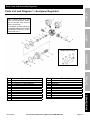
Parts List and Diagram 1 – Acetylene Regulator
R,($ K*#4("/$"&8
1 Body
2 H.P. Gauge (2.1" x 400 psi / 2800 kpa)
3 L.P. Gauge (2.1" x 30 psi / 200 kpa)
4 Inlet Nut (CGA 510)
5 Inlet Spigot
6 Filter
7 Valve Spring
8 Anti-Vibrator
9 Valve
10 Nozzle
11 Plunger
12 Diaphragm Assembly
R,($ K*#4("/$"&8
12A Nut
12B Diaphragm Plate
12C Diaphragm
12D Centralizer
13 Slip Ring
14 Adjusting Spring
15 Spring Button
16 Bonnet
17 Label
18 Adjusting Screw T-Bar
19 Outlet Adaptor
O&5/&8*8$#%&2-%n>b
When ordering parts from this
Parts List and Diagram always
take the number from the Part
column (on the left).
For example: To order a Body for
this regulator take the part number
from the Part column (1). So you
would order part 1.

Page 20 ;&(%$*4.8"4,7%<'*#$"&8#=%/7*,#*%4,77%>?@@@?@AA?BCDC1 Item 64407
EF;6GH I6JKLMN OPGGLMN QFLMG6MFMO6E6GPR
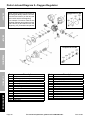
Parts List and Diagram 2 – Oxygen Regulator
R,($ K*#4("/$"&8
1 Body
2 H.P. Gauge (2.1" x 4000 psi / 28000 kpa)
3 L.P. Gauge (2.1" x 200 psi / 1400 kpa)
4 Inlet Nut (CGA 540)
5 Inlet Spigot
6 Filter
7 Valve Spring
8 Anti-Vibrator
9 Valve
10 Nozzle
11 Plunger
12 Diaphragm Assembly
12A Nut
12B Diaphragm Plate
12C Diaphragm
R,($ K*#4("/$"&8
12D Centralizer
13 Slip Ring
14 Adjusting Spring
15 Spring Button
16 Bonnet
17 Label
18 Adjusting Screw T-Bar
19 Outlet Adaptor
20 Safety Valve
20A Safety Body
20B Safety Rubber
20C Safety Seat
20D Safety Spring
20E Safety Cap
O&5/&8*8$#%&2-%n>b
O&5/&8*8$#%&2-%nbc
When ordering parts from this Parts List
and Diagram always take the number
from the Part column (on the left) and
add a suffix of F to the beginning.
For example: To order a Filter for this
regulator take the part number from the
Part column (6) and add an F to the
beginning. So you would order part A6.
Page is loading ...
Page is loading ...
Page is loading ...
Page is loading ...
-
 1
1
-
 2
2
-
 3
3
-
 4
4
-
 5
5
-
 6
6
-
 7
7
-
 8
8
-
 9
9
-
 10
10
-
 11
11
-
 12
12
-
 13
13
-
 14
14
-
 15
15
-
 16
16
-
 17
17
-
 18
18
-
 19
19
-
 20
20
-
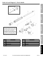 21
21
-
 22
22
-
 23
23
-
 24
24


Olsen Item 64407-UPC 792363644075 Owner's manual
- Category
- Power tools
- Type
- Owner's manual
- This manual is also suitable for
Ask a question and I''ll find the answer in the document
Finding information in a document is now easier with AI
Related papers
-
 Olsen Item 64407-UPC 193175340146 Owner's manual
-
 Olsen Item 64408-UPC 193175340139 Owner's manual
-
Chicago Electric 98958 Owner's manual
-
 Olsen 64408 Owner's manual
-
 Olsen Item 57574-UPC 193175417565 Owner's manual
-
 Olsen 63788 Owner's manual
-
 Olsen 63787 Owner's manual
-
 Olsen 63789 Owner's manual
-


Other documents
-
 Eastwood Lead Body Soldering Diffuser Tip Operating instructions
-
Sunnydaze Decor WKO-134 Installation guide
-
-
-
ESAB Welding and Cutting Outfit User manual
-
-
-
Harbor Freight Tools Portable Torch Kit with Oxygen and Acetylene Tanks User manual
-
Miller BDH Owner's manual
-
