Page is loading ...

ROOM AIR CONDITIONER
SERVICE MANUAL
CAUTION
- BEFORE SERVICING THE UNIT,
READ THE "SAFETY PRECAUTIONS" IN THIS MANUAL.
- ONLY FOR AUTHORIZED SERVICE
MODELS:
LWM1836TAS, LWM1836QCG, LWN2131QAG, Y5USC24-6R, WG2400R,
LWN2432QAS, LWN2433TCS, WG1800R, M1804R, Y5USC18-6R, LWM1836QAS,
HBLG1800R, HBLG2400R, M2403R, LWC243NSMM0, LWC243NSMM2, HBLG2350E
website http://biz.lgservice.com
e-mail http://www.lgeservice.com/techsup.html

—2—
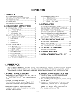
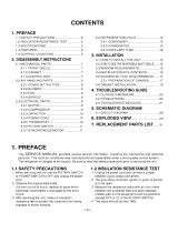
1. PREFACE
1.1 SAFETY PRECAUTIONS................................................................................................................................3
1.2 INSULATION RESISTANCE TEST.................................................................................................................3
1.3 SPECIFICATIONS...........................................................................................................................................3
1.4 FEATURES .....................................................................................................................................................4
1.5 CONTROL LOCATIONS.................................................................................................................................4
2.
DISASSEMBLY INSTRUCTIONS
2.1 MECHANICAL PARTS....................................................................................................................................5
2.1.1 FRONT GRILLE.....................................................................................................................................5
2.1.2 CABINET................................................................................................................................................5
2.1.3 CONTROL BOX.....................................................................................................................................5
2.2 AIR HANDLING PARTS..................................................................................................................................6
2.2.1 COVER (AT THE TOP)..........................................................................................................................6
2.2.2 BLOWER................................................................................................................................................6
2.2.3 FAN........................................................................................................................................................6
2.2.4 SHROUD................................................................................................................................................7
2.3 ELECTRICAL PARTS .....................................................................................................................................7
2.3.1 MOTOR..................................................................................................................................................7
2.3.2 COMPRESSOR .....................................................................................................................................7
2.3.3 CAPACITOR ..........................................................................................................................................7
2.3.4 POWER CORD......................................................................................................................................8
2.3.5 THERMISTOR........................................................................................................................................8
2.3.6 SYNCHRONOUS MOTOR.....................................................................................................................8
2.4 REFRIGERATION CYCLE..............................................................................................................................9
2.4.1 CONDENSER ........................................................................................................................................9
2.4.2 EVAPORATOR ......................................................................................................................................9
2.4.3 CAPILLARY TUBE.................................................................................................................................9
3.
INSTALLATION
3.1 HOW TO INSTALL THE UNIT.......................................................................................................................12
3.2
HOW TO USE THE REVERSIBLE INLET GRILLE
..................................................................................................................
12
3.3 WINDOW REQUIREMENTS.........................................................................................................................13
3.4 INSTALLATION KITS CONTENTS...............................................................................................................13
3.5 SUGGESTED TOOL REQUIREMENTS.......................................................................................................14
3.6 CABINET INSTALLATION ............................................................................................................................15
4.
TROUBLESHOOTING GUIDE
4.1 OUTSIDE DIMENSIONS...............................................................................................................................17
4.2 PIPING SYSTEM...........................................................................................................................................17
4.3 TROUBLESHOOTING GUIDE......................................................................................................................18
5. SCHEMATIC DIAGRAM
5.1 CIRCUIT DIAGRAM......................................................................................................................................27
5.2 ELECTRONIC CONTROL DEVICE ..............................................................................................................28
5.3
COMPONENTS LOCATION(FOR MAIN P.C.B ASM
).......................................................................................................29
5.4
COMPONENTS LOCATION(FOR DISPLAY P.C.B ASM)
.......................................................................................................29
6. EXPLODED VIEW..................................................................................................................................30
7. REPLACEMENT PARTS LIST........................................................................................................31
CONTENTS
—3—
1.1 SAFETY PRECAUTIONS
1. When servicing, set the POWER of CONTROL
BOARD to Off and unplug the power cord.
2. Observe the original lead dress.
If a short circuit is found, replace all parts which
have been overheated or damaged by the short
circuit.
3. After servicing, make an insulation resistance test to
prevent the customer's exposure to shock
hazards.
1.2
INSULATION RESISTANCE TEST
1. Unplug the power cord and connect a jumper
between 2 pins (black and white).
2. The grounding conductor (green or green and
yellow) is to be open.
3. Measure the resistance value with an ohm meter
between the jumpered lead and each exposed
metallic part on the equipment at all Mode [except
POWER OFF].
4. The value should be over 1 MΩ.
1. PREFACE
This service manual provides various service information, including the mechanical and electrical parts, etc.
This room air conditioner was manufactured and assembled under a strict quality control system.
The refrigerant is charged at the factory. Be sure to read the safety precautions prior to servicing the unit.
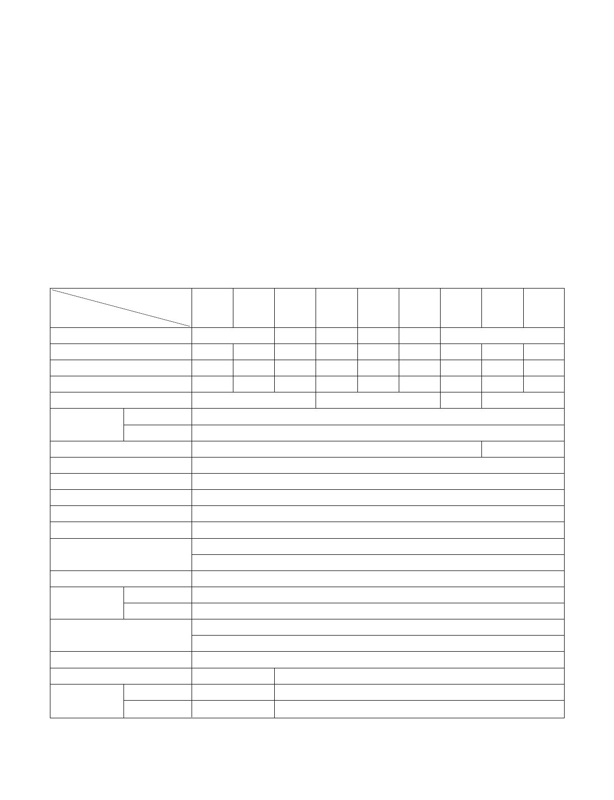
1.3 SPECIFICATIONS
M1804R
WG1800R
HBLG1800R
LWM1836TASL
WN1836QCG
LWM1863QAS
Y5USC18-6R
LWN2131QAG
WG2400R
HBLG2400R
M2403R
LWN2432QAS
Y5USC24-6R
LWC243NSMM0
LWN2433TCS LWC243NSMM2 HBLG2350E
POWER SUPPLY
COOLING CAPACITY (Btu/h)
INPUT (W)
RUNNING CURRENT (A)
REFRIGERANT CHARGE (g)
OPERATING INDOOR (°C)
TEMPERATURE OUTDOOR (°C)
FAN, INDOOR
FAN, OUTDOOR
FAN SPEEDS, FAN/COOLING
FAN MOTOR
OPERATION CONTROL
ROOM TEMP. CONTROL
AIR DIRECTION CONTROL
CONSTRUCTION
PROTECTOR COMPRESSOR
FAN MOTOR
POWER CORD
DRAIN SYSTEM
NET WEIGHT (lbs/kg)
OUTSIDE DIMENSION
(inch)
(W x H x D) (mm)
1Ø, 208/230V, 60Hz
1Ø, 220V, 60Hz 1Ø, 220V, 60Hz
1Ø, 208/230V, 60Hz
1Ø, 220V, 60Hz 1Ø, 208/230V, 60Hz
17,500/18,000 17,500 18,000 21,000 23,500/24,000 24,000 24,000 23,000 23,000/23.500
1,800/1,850 1,840 1,050 2,470 2,760/2,820 2,820 2,420 2,540 2,450/2,500
9.0/8.3 8.5 8.3 10.3 13.7/12.7 12.7/12.9 11.2 11.5 12.2/11.3
710(25.1 OZ) 995(35.1 OZ)/980(34.6 OZ) 880(31 OZ) 985(34.7 OZ)
26.7(DB) 19.4(WB)
35(DB) 23.9(WB)
BLOWER TURBO
PROPELLER TYPE FAN WITH SLINGER-RING
3/3
6 POLES
TOUCH PANEL
THERMISTOR
VERTICAL LOUVER(RIGHT & LEFT)
HORIZONTAL LOUVER(UP & DOWN)
SLIDE IN-OUT CHASSIS
INTERNAL OVERLOAD PROTECTOR
INTERNAL THERMAL PROTECTOR
1.6m (3 WIRE WITH GROUNDING)
ATTACHMENT PLUG(CORD-CONNECTED TYPE)
DRAIN PIPE OR SPLASHED BY FAN SLINGER
120/54 143/65
26 x 16
27
/32 x 26
9
/16 26 x 16
27
/32 x 30
5
/16
660 x 428 x 675 660 x 428 x 770
MODELS
ITEMS
* DB:Dry Bulb
**
WB:Wet Bulb
NOTE : Specifications are subject to minor change without notice for further improvement.
1.4 FEATURES
• Designed for cooling only.
• Powerful and quiet cooling.
• Slide-in and slide-out chassis for the simple installation
and service.
• Reversible inlet grille.
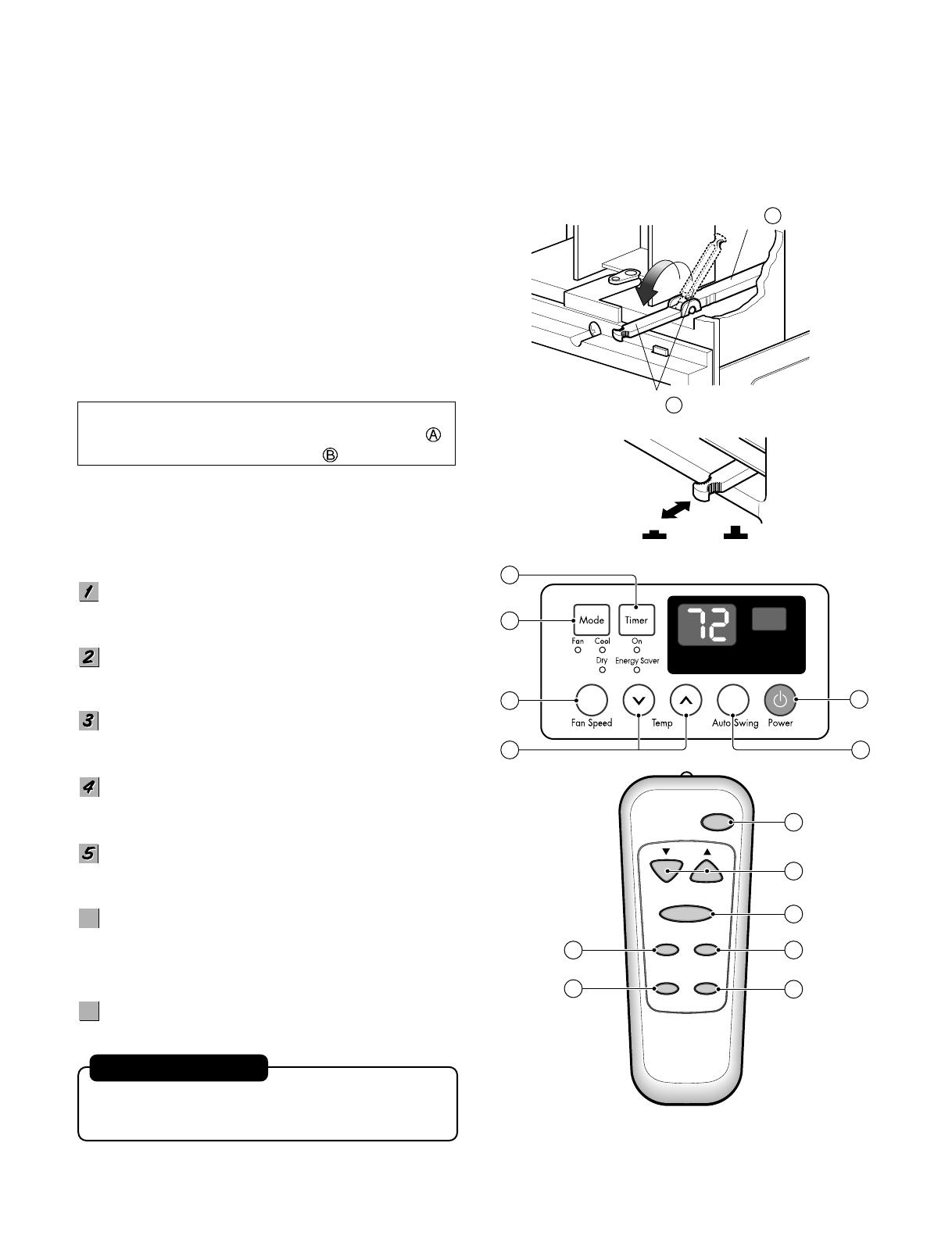
1.5 CONTROL LOCATIONS
• VENTILATION
The ventilation lever must be in the CLOSE position in
order to maintain the best cooling conditions.
When a fresh air is necessary in the room, set the
ventilation lever to the OPEN position.
The damper is opened and room air is exhausted.
NOTE: Before using the ventilation feature, make
the lever, as shown. First, pull down part
to horizontal line with part .
Precaution: The Remote Control unit will not function
properly if strong light strikes the sensor
window of the air conditioner or if there
are obstacles between the Remote
Control unit and the air conditioner.
POWER BUTTON
Operation starts, when this button is pressed and stops
when you press the button again.
OPERATION MODE SELECTION BUTTON
Select Cooling, or Fan or Dehumidification(Dry) mode
with button. (Dry mode is not to all models.)
ON/OFF TIMER BUTTON
Set the time of starting and stopping operation. The
timer is set by 1 hour.
FAN SPEED SELECTOR
Select the fan speed in three steps.
- High [F3] ➔ Low[F1] ➔ Med[F2]➔ High[F3]... .
ROOM TEMPERATURE SETTING BUTTON
Control the room temperature within a range of 60°F to
86°F by 1°F.
ENERGY SAVER
(Available In some models)
The fan stops when the compressor stops cooling.
Approximately every 3 minutes the fan will turn on and
check the room air to determine if cooling is needed.
AUTO SWING
Control the horizontal air direction by air swing system.
• Side air-intake, side cooled-air discharge.
• Built in adjustable THERMISTOR.
• Washable one-touch filter.
• Compact size.
—4—
Part A
Part B
VENTCLOSE OPEN
2
3
1
4
5 7
Power
Temp
Fan Speed
Timer Mode
Energy
Saver
Auto
Swing
1
4
3
6
2
7
5
6
6
AUTO RESTART
In case the power comes on again after a power failure,
the unit runs as previous setting operation.
(Available
in some models)
7
7
—5—
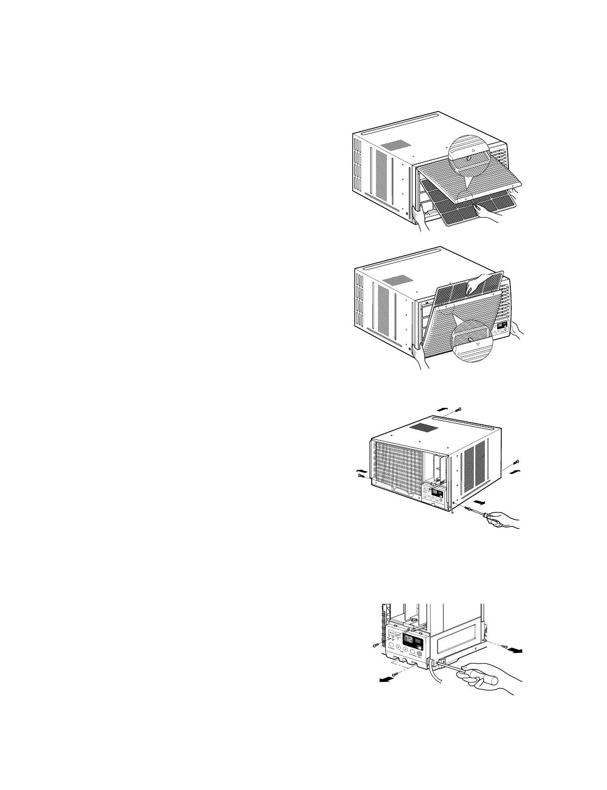
2.1 MECHANICAL PARTS
2.1.1 FRONT GRILLE
1. Open the inlet grille upward or downward.
2. Remove the screw which fastens the front grille.
3. Pull the front grille from the right side.
4. Remove the front grille. (See Fig. 1)
5. Re-install the component by referring to the
removal procedure.
NOTE: Mark ∆ of inlet grille means opening direction.
2.1.2 CABINET
1. After disassembling the FRONT GRILLE, remove
the screws which fasten the cabinet at both sides.
Keep these for later use.
2. Remove the two screws which fasten the cabinet
at back. (See Fig. 2)
3. Pull the base pan forward.
2.1.3 CONTROL BOX
1. Remove the front grille. (Refer to section 2.1.1)
2. Pull the base pan forward so that you can remove
the 2 screws which fasten the cover control at the
right side. (See Fig. 3)
3. Remove the 3 screws which fasten the control
box. (See Fig. 3)
4. Discharge the capacitor by placing a 20,000 ohm
resistor across the capacitor terminals.
5. Disconnect two wire housings in the control box.
6. Pull the control box forward completely.
7. Re-install the components by referring to the
removal procedure. (See Fig. 3)
(Refer to the circuit diagram found on page 24 in
this manual and on the control box.)
2. DISASSEMBLY INSTRUCTIONS
— Before the following disassembly, POWER SWITCH is set to OFF and disconnected the power cord.
Figure 1
Figure 2
Figure 3
—6—
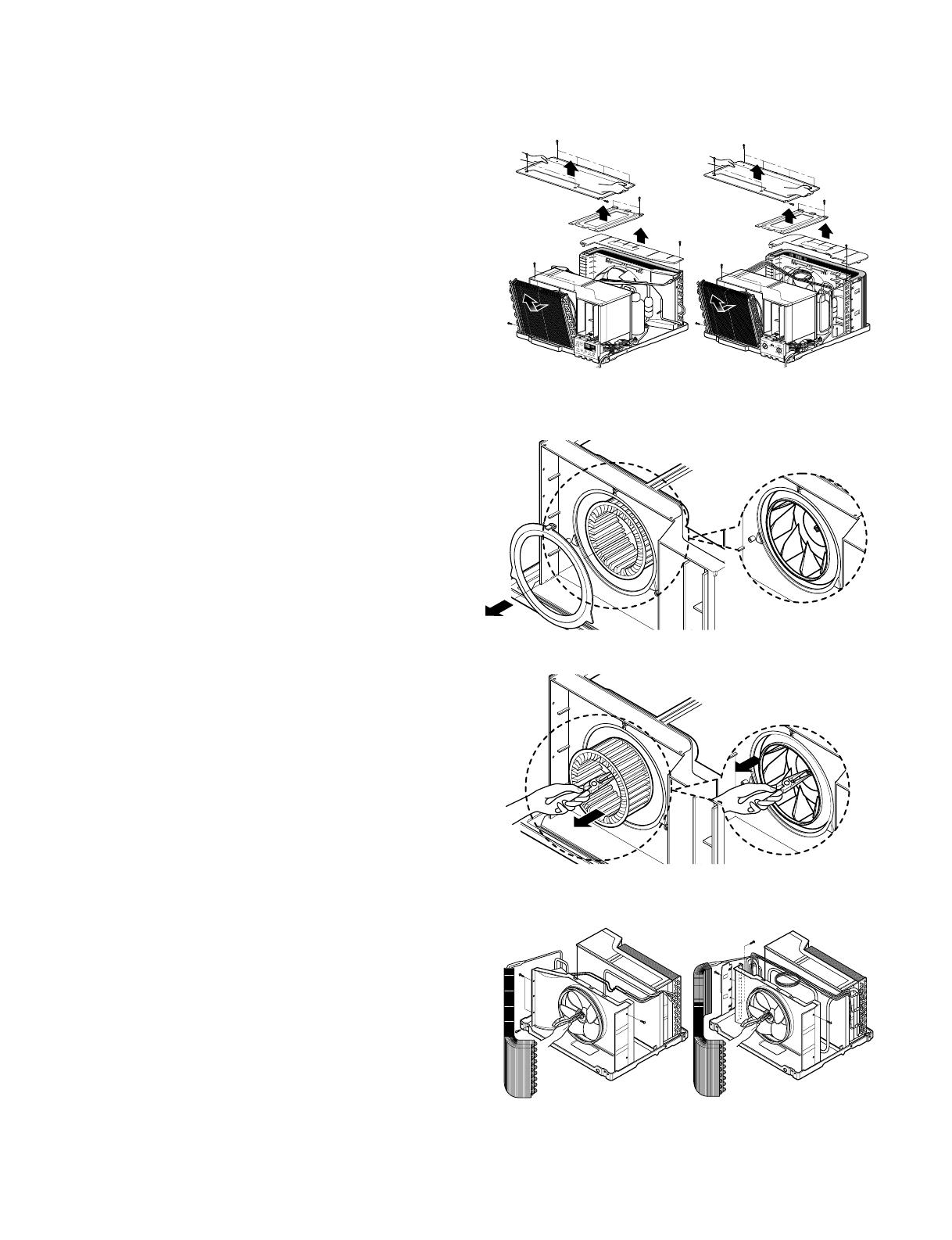
2.2 AIR HANDLING PARTS
2.2.1 COVER (AT THE TOP)
1. Remove the front grille. (Refer to section 2.1.1)
2. Remove the cabinet. (Refer to section 2.1.2)
3. Remove 11 screws which fasten the brace and
covers.
4. Remove the covers and the brace. (See Fig. 4)
5. Re-install the components by referring to the
removal procedure, above.
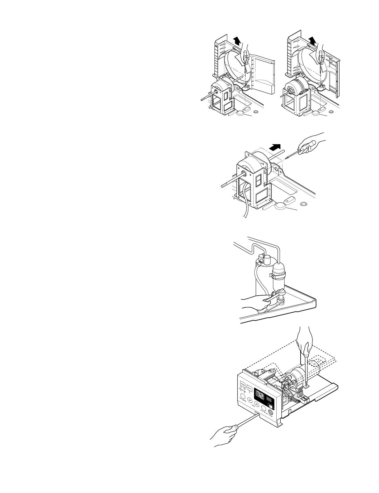
2.2.2 BLOWER
1. Remove the cover. (Refer to section 2.2.1)
2. Remove the 3 screws which fasten the
evaporator at the left side and the top side.
(See Fig. 4)
3. Move the evaporator sideward carefully.
4. Remove the orifice from the air guide carefully.
5. Remove the clamp spring which is clamped to the
boss of blower by hand plier. (See Fig. 5)
6. Pull the blower outward, without touching blades.
(See Fig. 6)
7. Re-install the components by referring to the
removal procedure, above.
2.2.3 FAN
1. Remove the cabinet. (Refer to section 2.1.2)
2. Remove the brace and shroud cover.
(Refer to section 2.2.1)
3. Remove the 5 screws which fasten the condenser.
4. Move the condenser sideways carefully.
5. Remove the clamp which secures the fan.
6. Remove the fan. (See Fig. 7)
7. Re-install the components by referring to the
removal procedure, above.
Figure 4 (a) Figure 4 (b)
Figure 5
Figure 6
Figure 7 (a) Figure 7 (b)
—7—
2.2.4 SHROUD
1. Remove the fan. (Refer to section 2.2.3)
2. Remove the 2 screws which fasten the shroud.
3. Remove the shroud. (See Fig. 8)
4. Re-install the component by referring to the
removal procedure, above.
2.3 ELECTRICAL PARTS
2.3.1 MOTOR
1. Remove the cabinet. (Refer to section 2.1.2)
2. Remove the cover control and disconnect a wire
housing in control box. (Refer to section 2.1.3)
3. Remove the blower. (Refer to section 2.2.2)
4. Remove the fan. (Refer to section 2.2.3)
5. Remove the 4 screws which fasten the motor.
(See Fig. 9)
6. Remove the motor.
7. Re-install the components by referring to the
removal procedure, above.
2.3.2 COMPRESSOR
1. Remove the cabinet. (Refer to section 2.1.2)
2. Discharge the refrigerant by using a Refrigerant
Recovery System.
3. Disconnect the 3 leads from the compressor.
4. After purging the unit completely, unbraze the
suction and discharge tubes at the compressor
connections.
5. Remove the 3 nuts and the 3 washers which
fasten the compressor. (See Fig. 10)
6. Remove the compressor.
7. Re-instill the components by referring to the
removal procedure, above.
2.3.3 CAPACITOR
1. Remove the control box. (Refer to section 2.1.3)
2. Remove the screw which fasten the display panel.
3. Disconnect the 2 leads from the rocker switch and
remove the panel.
4. Remove a screw and unfold the control box.
(See Fig. 11)
5. Remove the screw and the clamp which fastens
the capacitor. (See Fig. 11)
6. Disconnect all the leads of capacitor terminals.
7. Re-install the components by referring to the
removal procedure, above.
Figure 8 (a) Figure 8 (b)
Figure 9
Figure 10
Figure 11
—8—
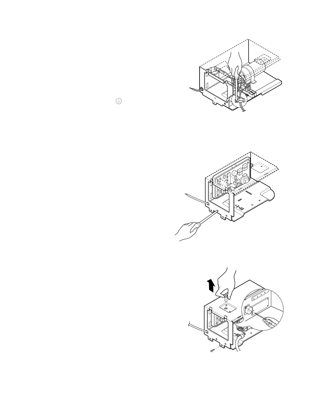
2.3.4 POWER CORD
1. Remove the control box. (Refer to section 2.1.3)
2. Unfold the control box. (Refer to section 2.3.3)
3. Disconnect the grounding screw from the control
box.
4. Disconnect 2 receptacles.
5. Remove a screw which fastens the clip cord.
6. Pull the power cord. (See Fig. 12)
7. Re-install the component by referring to the
removal procedure, above.
(Use only one ground-marked hole for ground
connection.)
8. If the supply cord of this appliance is damaged, it
must be replaced by the special cord.
(The special cord means the cord which has the
same specification marked on the supply cord
fitted to the unit.)
2.3.5 THERMISTOR
1. Remove the control box. (Refer to section 2.1.3)
2. Unfold the control box. (Refer to section 2.3.3)
3. Disconnect the thermistor terminals from main
P.W.B assembly.
4. Remove the thermistor.
5. Re-install the components by referring to the
removal procedure above. (See Figure 13)
2.3.6 SYNCHRONOUS MOTOR
1. Remove the control box. (Refer to section 2.1.3)
2. Unfold the control box. (Refer to section 2.3.3)
3. Remove the crankshaft.
4. Disconnect all the leads of the synchronous
motor.
5. Remove the 2 screws which fasten the
synchronous motor. (See Fig. 14)
6. Re-install the components by referring to the
removal procedure, above.
Figure 13
Figure 12
Figure 14

—9—
2.4 REFRIGERATION CYCLE
2.4.1 CONDENSER
1. Remove the cabinet. (Refer to section 2.1.2)
2. Remove the brace and the shroud cover.
(Refer to section 2.2.1)
3. Remove the 5 screws which fasten the condenser.
4. After discharging the refrigerant completely,
unbraze the interconnecting tube at the condenser
connections.
5. Remove the condenser.
6. Re-install the components by referring to notes.
(See Fig. 15)
2.4.2 EVAPORATOR
1. Remove the cabinet. (Refer to section 2.1.2)
2. Remove the top cover and the brace.
(Refer to section 2.2.1)
3. Discharge the refrigerant completely.
4. Remove the 3 screws which fasten the evaporator
at the left side and the top side.
5. Move the evaporator sideward carefully and then
unbraze the interconnecting tube at the evaporator
connectors.
6. Remove the evaporator.
7. Re-install the components by referring to notes.
(See Fig. 16)
2.4.3 CAPILLARY TUBE
1. Remove the cabinet. (Refer to section 2.1.2)
2. Remove the brace. (Refer to section 2.2.1)
3. After discharging the refrigerant completely,
unbraze the interconnecting tube at the capillary
tube.
4. Remove the capillary tube.
5. Re-install the components by referring to notes.
Figure 15 (a)
Figure 15 (b)
Figure 16
Discharge the refrigerant system using Freon
TM
Recovery System.
If there is no valve to attach the recovery system,
install one (such as a WATCO A-1) before
venting the Freon
TM
. Leave the valve in place
after servicing the system.
CAUTION

—10—
— Replacement of the refrigeration cycle.
1. When replacing the refrigeration cycle, be sure to
discharge the refrigerant system using a Freon
TM
recovery System.
If there is no valve to attach the recovery system,
install one (such as a WATCO A-1) before venting
the Freon
TM
. Leave the valve in place after
servicing the system.
2. After discharging the unit completely, remove the
desired component, and unbrace the pinch-off
tubes.
3. Solder service valves into the pinch-off tube ports,
leaving the valves open.
4. Solder the pinch-off tubes with Service valves.
5. Evacuate as follows.
1) Connect the vacuum pump, as illustrated Fig.
17A.
2) Start the vacuum pump, slowly open manifold
valves A and B with two full turns
counterclockwise and leave the valves closed.
The vacuum pump is now pulling through valves
A and B up to valve C by means of the manifold
and entire system.
3) Operate the vacuum pump for 20 to 30 minutes,
until 600 microns of vacuum is obtained. Close
valves A and B, and observe vacuum gauge for
a few minutes. A rise in pressure would
indicate a possible leak or moisture remaining in
the system. With valves A and B closed, stop
the vacuum pump.
4) Remove the hose from the vacuum pump and
place it on the charging cylinder. See Fig. 17B.
Open valve C.
Discharge the line at the manifold connection.
5) The system is now ready for final charging.
6. Recharge as follows :
1) Refrigeration cycle systems are charged from the
High-side. If the total charge cannot be put
in the High-side, the balance will be put in the
suction line through the access valve which you
installed as the system was opened.
2)
Connect the charging cylinder as shown in Fig. 17B.
With valve C open, discharge the hose at the
manifold connection.
3) Open valve A and allow the proper charge to
enter the system. Valve B is still closed.
4) If more charge is required, the high-side will not
take it. Close valve A.
5) With the unit running, open valve B and add the
balance of the charge.
a. Do not add the liquid refrigerant to the Low-
side.
b. Watch the Low-side gauge; allow pressure to
rise to 30 lbs.
c. Turn off valve B and allow pressure to drop.
d. Repeat steps B and C until the balance of the
charge is in the system.
6) When satisfied the unit is operating correctly,
use the pinch-off tool with the unit still running
and clamp on to the pinch-off tube. Using a tube
cutter, cut the pinch-off tube about 2 inches from
the pinch-off tool. Use sil-fos solder and solder
pinch-off tube closed. Turn off the unit, allow it to
set for a while, and then test the leakage of the
pinch-off connection.
NOTES
If high vacuum equipment is used, just crack
valves A and B for a few minutes, then open
slowly with the two full turns counterclockwise.
This will keep oil from foaming and being
drawn into the vacuum pump.
CAUTION

—11—
Equipment needed: Vacuum pump, Charging cylinder, Manifold gauge, Brazing equipment. Pinch-off tool
capable of making a vapor-proof seal, Leak detector, Tubing cutter, Hand Tools to remove components, Service
valve.
A
COMPOUND GAUGE
EVAPORATOR
(LOW PRESSURE SIDE)
COMPRESSOR
CAPILLARY TUBE
CONDENSER
(HIGH PRESSURE SIDE)
SEE INSETS
BELOW
MANIFOLD
GAUGE
B
Figure 17A-Pulling Vacuum
Figure 17B-Charging
A
B
EXTERNAL
VACUUM PUMP
A
CHARGING
CYLINDER
LOW
HI
B
C
—12—
3. INSTALLATION
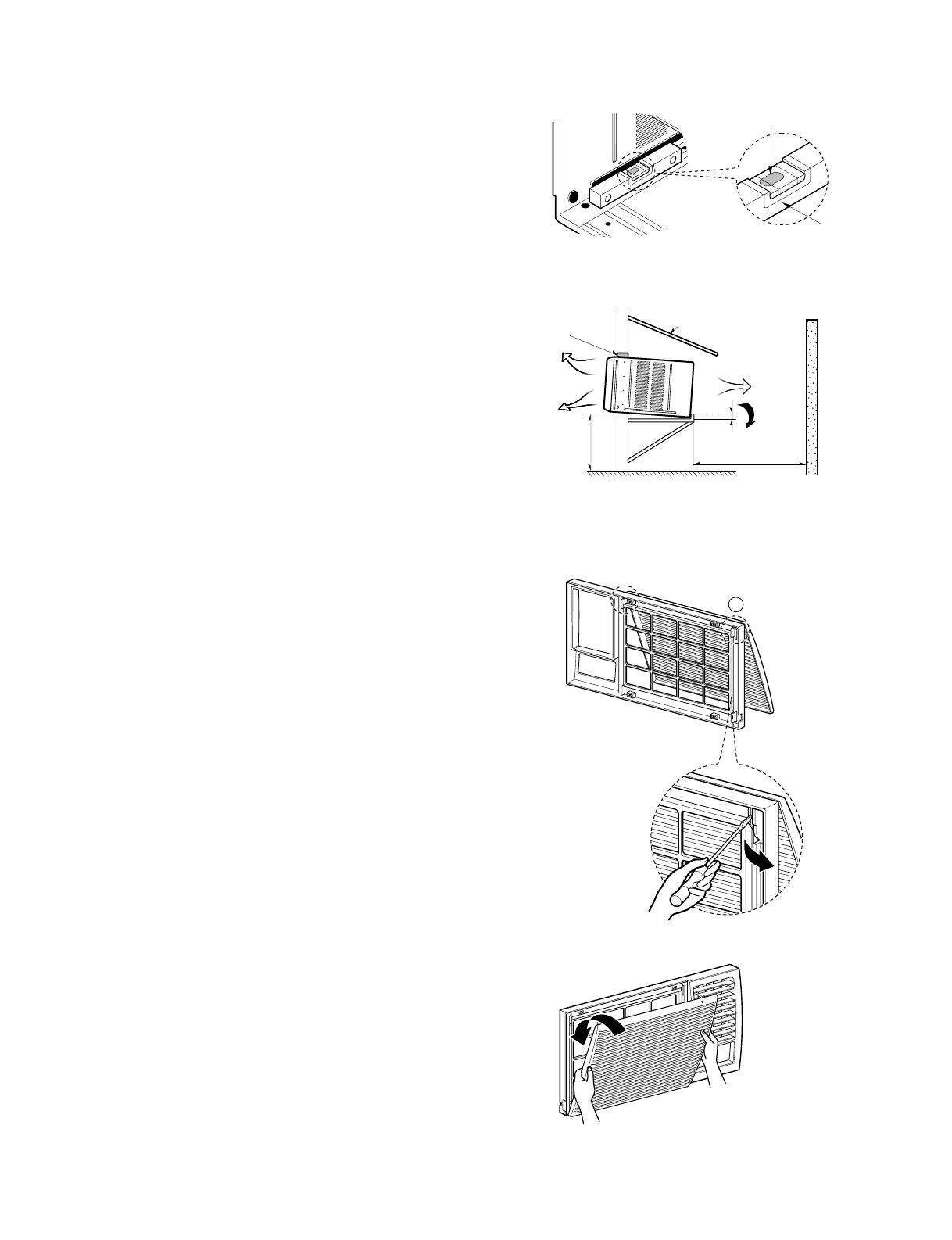
3.1 HOW TO INSTALL THE UNIT
1. To avoid vibration and noise, make sure the unit is installed
securely and firmly.
2. Install the unit where the sunlight does not shine directly on
the unit.
If the unit receives direct sunlight, build an awning to shade
the cabinet.
3. There should be no obstacle, like a fence, within 20" which
might restrict heat radiation from the condenser.
4. To prevent reducing performance, install the unit so that
louvers of the cabinet are not blocked.
5. Install the unit a little obliquely outward not to leak the
condensed water into the room (about 1/2" or 1/4" bubble
with level).
6. Install the unit with its bottom portion 30~60" above the floor
level.
7. Stuff the foam between the top of the unit and the wall to
prevent air and insects from getting into the room.
8. The power cord must be connected to an independent
circuit. The green wire must be grounded.
9. Connect the drain tube to the base pan hole in the rear side
if you need to drain (consult a dealer).
Plastic hose or equivalent may be connected to the drain
tube.
3.2 HOW TO USE THE REVERSIBLE
INLET GRILLE
The grille is designed to clean the filter both upward and
downward.
A. BEFORE ATTACHING THE FRONT
GRILLE TO THE CABINET, IF YOU WANT
TO PULL OUT THE FILTER UPWARD;
1. Open the inlet grille slightly (a).
2. Turn inside out the front grille (a).
3. Disassemble the inlet grille from the front grille with
separating the hinged part by inserting a straight type
screw-driver tip (b).
4. Then, rotate the inlet grille 180 degrees and insert the hooks
into bottom holes of the front grille.
5. Insert the filter and attach the front grille to the cabinet.
B. IF YOU WANT TO PULL OUT THE FILTER
DOWNWARD;
The grille is already designed for that way.
About 1/2"
Over 20"
HEAT
RADIATION
FENCE
AWNING
FOAM
COOLED
AIR
30-60"
Level
1/4 Bubble
(b)
b
(a)
(c)

—13—
3.3 WINDOW REQUIREMENTS
NOTE: All supporting parts should be secured to firm wood,
masonry, or metal.
The models of the specific area don't contain
installation feit.
3.3.1 WINDOW REQUIREMENTS
1. This unit is designed for installation in standard
double hung windows with actual opening widths from
29" to 41".
The top and bottom window sashes must open
sufficiently to allow a clear vertical opening of 18"
from the bottom of the upper sash to the window
stool.
2. The stool offset (height between the stool and sill)
must be less than 1
1
/
4
".
3.4 INSTALLATION KITS CONTENTS
29" to 41"
18" min
Offset
Less
than 1
1
/4"
Sill
Exterior
Interior wall
26" min.
(Without frame curtain)
Stool
Foam-PE
(Adhesive-Backed)
Foam-PE
(Adhesive-Backed)
Type C (5) Type D (2)
Type A (14)
Carriage Bolt (2) Lock Nut (4)
Top retainer bar
Type B (7)
Foam strip
(Plain-Back)
Right frame
curtain
Window locking
bracket
Left frame
curtain
Frame guide(2)
Sill
bracket
(2)
Support bracket(2)
—14—
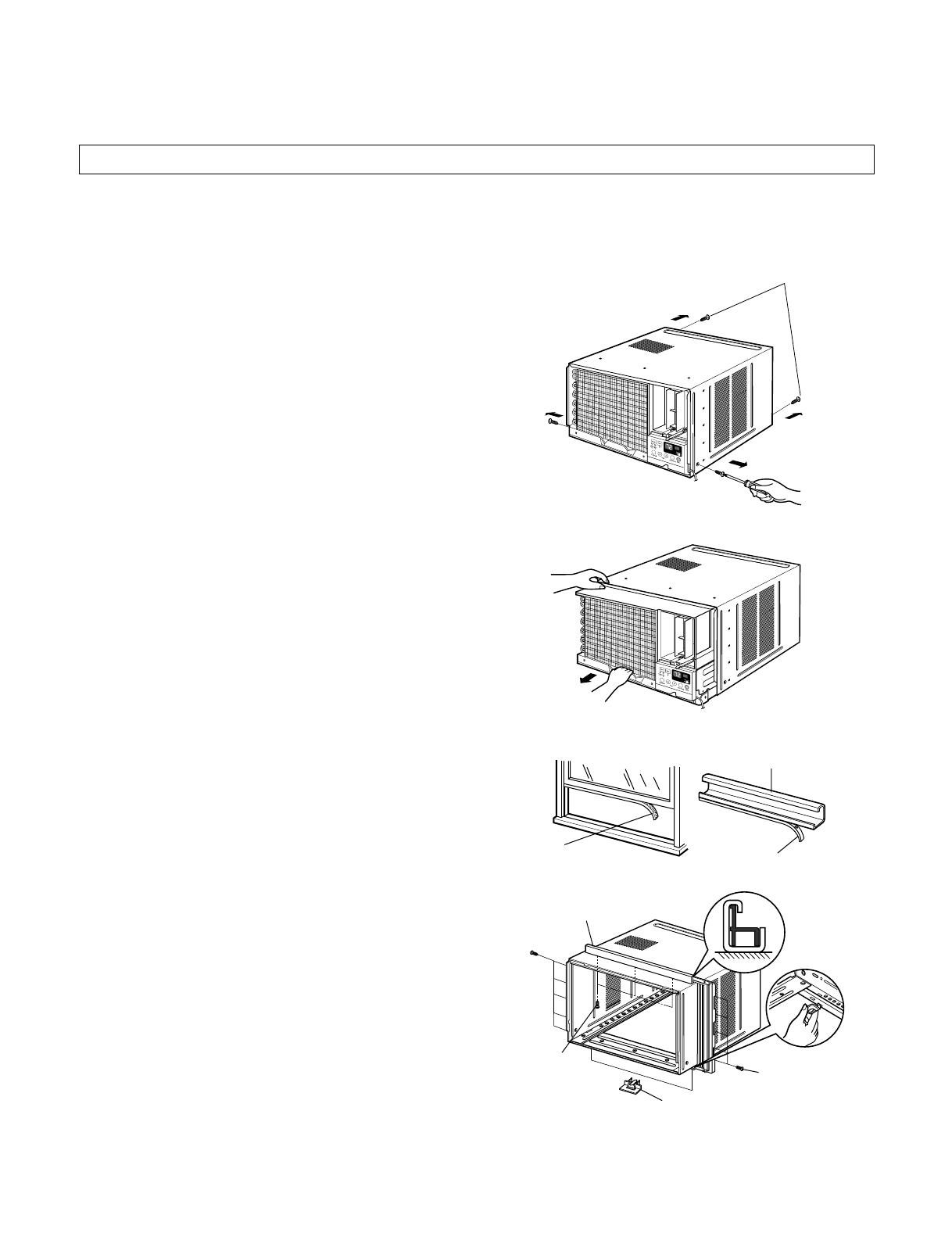
3.5.1 PREPARATION OF CHASSIS
1. Remove the screws which fasten the cabinet at both sides
and at the back. Keep these two screws which fasten the
cabinet at both sides for later use.
2. Slide the unit out from the cabinet by gripping the base pan
handle and pulling forward while bracing the cabinet.
3. Cut the window sash seal to the proper length. Peel off the
backing and attach the Foam-PE to the underside of the
window sash.
4. Remove the backing from Foam-PE with 3 holes and attach
it to the bottom of the Top retainer bar.
5. Attach the Top retainer bar onto the top of the cabinet with 3
screws (Type A).
6. Insert the Frame guides into the bottom of the cabinet.
7. Insert the Frame Curtain into the Top retainer bar and
Frame guides.
8. Fasten the curtains to the unit with 10 screws (Type A) at
both sides.
SCREWDRIVER(+, -), RULER, KNIFE, HAMMER, PENCIL, LEVEL
Foam-PE
Top retainer bar
Top retainer bar
Foam-PE
Screw
(Type A)
Screw(Type A)
Frame guide
Shipping screws
Figure 18
Figure 19
Figure 20
Figure 21
3.5 SUGGESTED TOOL REQUIREMENTS
—15—
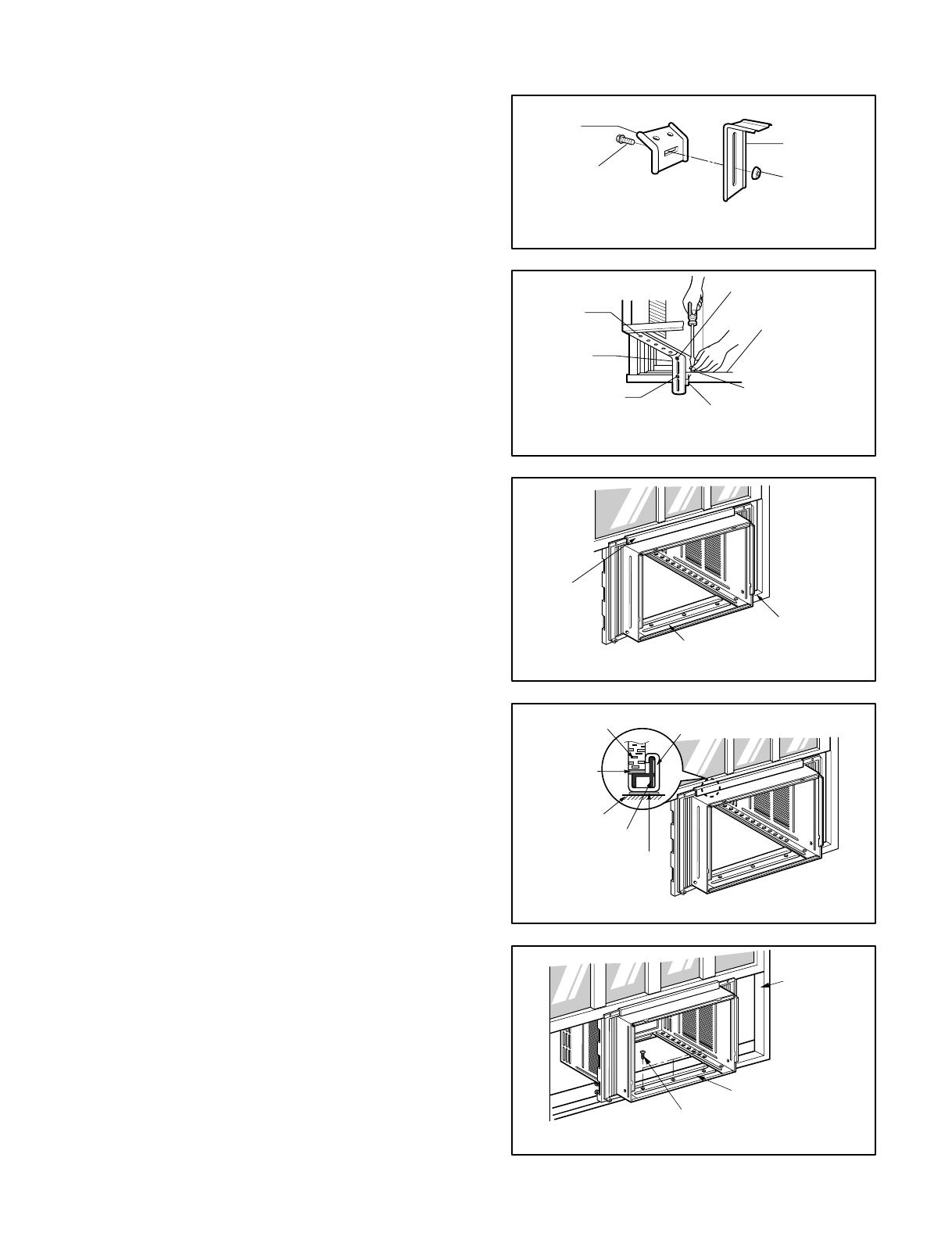
3.6 CABINET INSTALLATION
1. Open the window. Mark a line on the center of the window
stool between the side window stop moldings.
Loosely attach the sill bracket to the support bracket using
the carriage bolt and the lock nut.
2. Attach the sill bracket to the window sill using the screws
(Type B).
Carefully place the cabinet on the window stool and align the
center mark on the bottom front with the center line marked
window stool.
3. Using the M-screw and the lock nut, attach the support
bracket to the cabinet track hole. Use the first track hole
after the sill bracket on the outer edge of the window sill.
Tighten the carriage bolt and the lock nut. Be sure the
cabinet slants outward.
CAUTION: Do not drill a hole in the bottom pan. The unit is
designed to operate with approximately 1/2" of
water in bottom pan.
4. Pull the bottom window sash down behind the Top retainer
bar until they meet.
NOTE: 1. Do not pull the window sash down so tightly that the
movement of Frame curtain is restricted. Attach the
cabinet to the window stool by driving the screws
(Type B) through the cabinet into window stool.
2. The cabinet should be installed with a very slight tilt
downward toward the outside.
Support
Bracket
Lock nut
Sill
Bracket
Carriage
Bolt
(M-Screw)
Front angle
Window stool
Window sash
Top retainer bar
Cabinet
Foam-PE
Frame curtain
Screw(Type B)
Front Angle
Sash track
Foam-PE
Cabinet
Track hole
Support
Bracket
Carriage bolt
and lock nut
Machine screw (Type D)
and lock nut
Outer edge
of window
sill
Screw(Type B)
Sill bracket
Top
retainer
bar
Figure 22
Figure 23
Figure 24
Figure 25
Figure 26
—16—
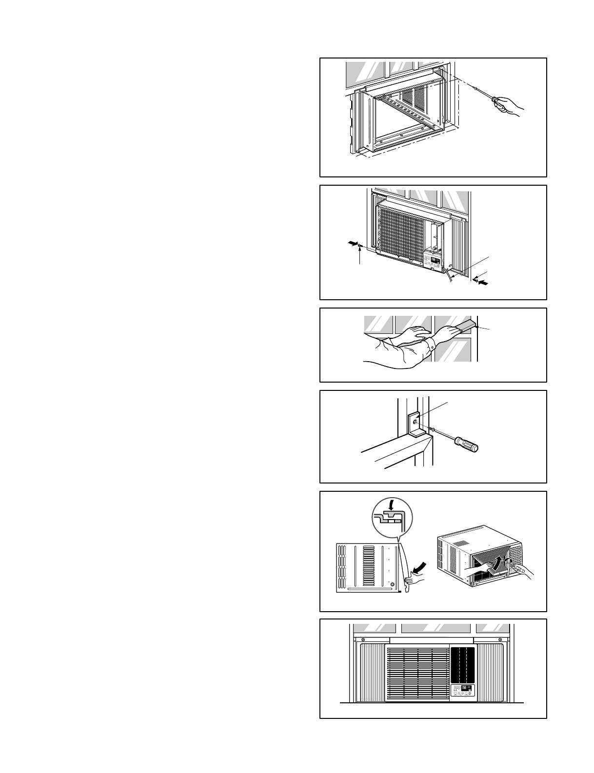
5. Pull each Frame curtain fully to each window sash
track, and pull the bottom window sash down behind
the Top retainer bar until it meets.
6. Attach each Frame curtain the window sash by using
screws (Type C). (See Fig. 27)
7. Slide the unit into the cabinet. (See Fig. 28)
CAUTION: For security purpose, reinstall screws (Type
A) at cabinet's sides.
8. Cut the Foam-strip to the proper length and insert
between the upper window sash and the lower
window sash. (See Fig. 29)
9. Attach the Window locking bracket with a screw
(Type C). (See Fig. 30)
10. Attach the front grille to the cabinet by inserting the
tabs on the grille into the tabs on the front of the
cabinet. Push the grille in until it snaps into place.
(See Fig.31)
11. Lift the inlet grille and secure it with a screw (Type A)
through the front grille. (See Fig. 31)
12. Window installation of room air conditioner is now
completed.
Power Cord
Screw (Type A)
Screw
Window locking
bracket
Foam-Strip
Screw(Type C)
Figure 27
Figure 28
Figure 29
Figure 30
Figure 31
Figure 32
—17—
4. TROUBLESHOOTING GUIDE
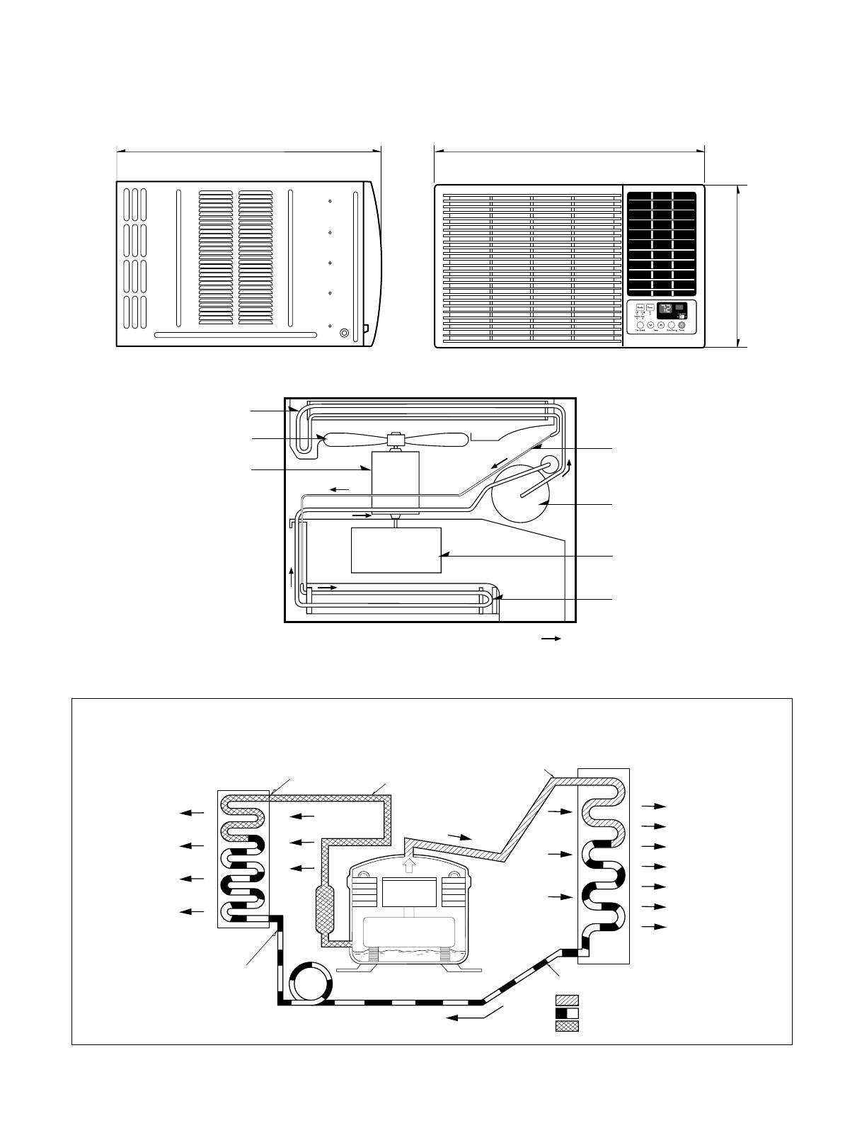
4.1 OUTSIDE DIMENSIONS
675(770)
660
428
CAPILLARY TUBE
COMPRESSOR
BLOWER
EVAPORATOR COIL
CONDENSER COIL
FAN
MOTOR
: REFRIGERANT FLOW
4.2 PIPING SYSTEM
Following is a brief description of the important components and their functions in the refrigeration system.
Refer to Fig. 33 to follow the refrigeration cycle and the flow of the refrigerant in the cooling cycle.
MOTOR
COMPRESSOR
OIL
(LIQUID REFRIGERANT)
CAPILLARY TUBE
OUTSIDE COOLING
AIR FOR REFRIGERANT
PASS THROUGH
SUCTION LINE
COOL LOW PRESSURE VAPOR
COOLED
AIR
COMPLETE LIQUID
BOIL OFF POINT
LIQUID
PRESSURE
DROP
ROOM AIR HEAT LOAD
VAPOR INLET
HOT
DISCHARGED
AIR
LIQUID OUTLET
HIGH PRESSURE VAPOR
LIQUID PEFRIGERANT
LOW PRESSURE VAPOR
ROOM AIR CONDITIONER
EVAPORATOR COILS CONDENSER COILS
CYCLE OF REFRIGERATION
Figure 33
—18—
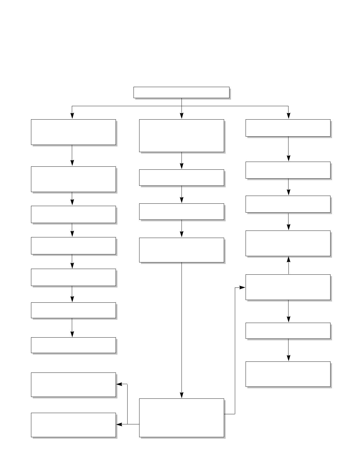
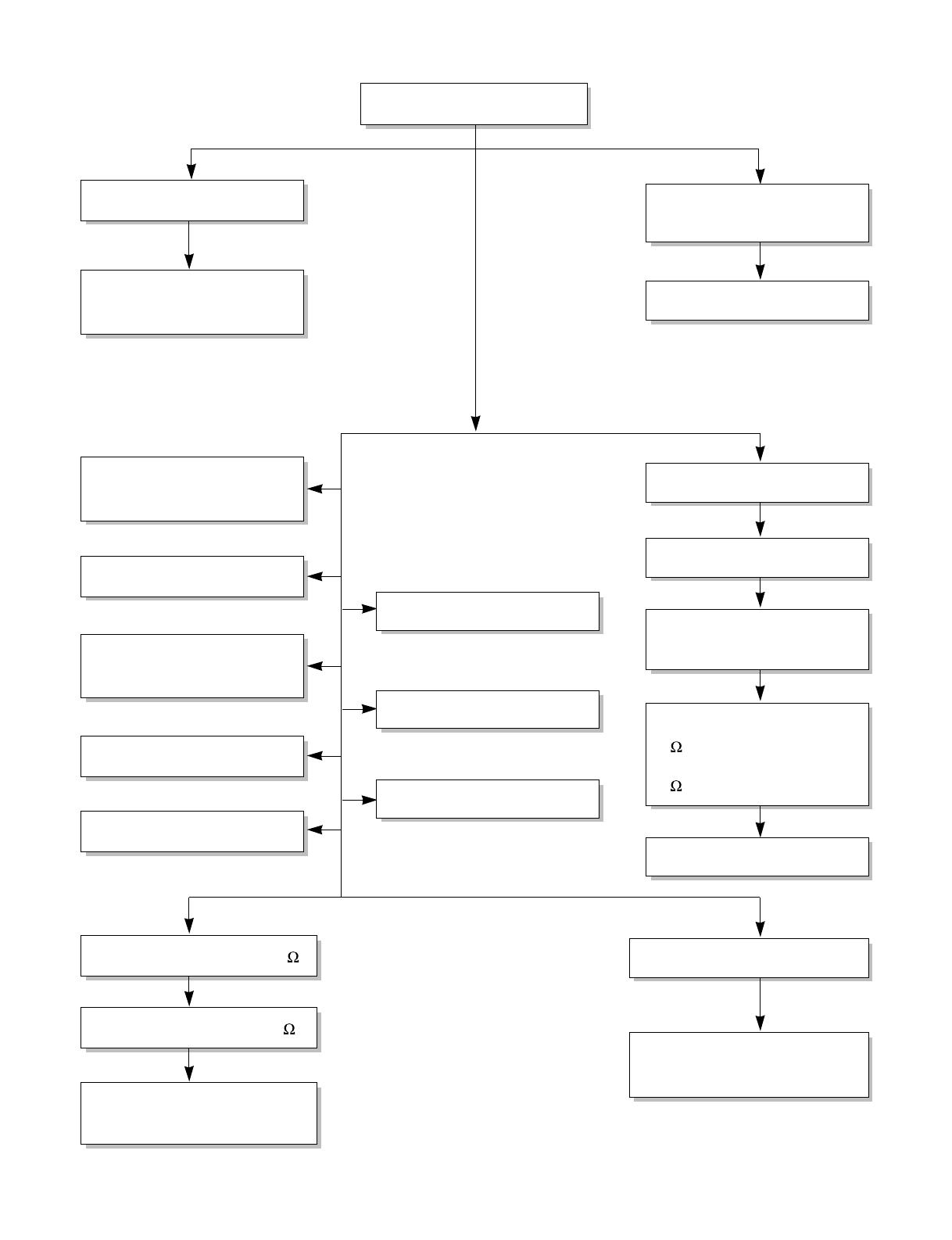
4.3 TROUBLESHOOTING GUIDE
In general, possible trouble is classified in two causes.
The one is called Starting Failure which is caused from an electrical defect, and the other is Ineffective Air
Conditioning caused by a defect in the refrigeration circuit and improper application.
Unit runs but poor cooling
Ineffective Cooling
Check of outdoor coil
(heat exchanger) & the fan
operation.
Check gas leakage.
Repair gas leak.
Replacement of unit if the
unit is beyond repair.
Satisfactory operation with
temperature difference of
inlet & outlet air ; 44.6~50°F
Check heat load increase.
Unexpected residue
Overloaded Circuit
Check of inside gas
pressure.
Adjusting of refrigerant
charge
Malfunction of compressor
Replacement of
compressor
Check of cold air circulation
for smooth flow.
Dirty indoor coil
(Heat exchanger)
Malfunction of fan
Clogged of air filter
Obstruction at air outlet
Correct above trouble
Stop of auto air-swing
Check clogging in
refrigeration circuit.
Repair clogging in
refrigeration circuit.
—19—
Fails to Start
Check of circuit breaker
and fuse.
Check of control panel.
Only fan fails to start.
Improper wiring.
Defect of fan motor
capacitor.
Irregular motor resistance
( ).
Irregular motor insulation
( ).
Replacement of fan motor
Regular but fails to start
Replacement of compressor
(locking of rotor, metal)
Improper thermistor setting
Loose terminal connection.
Improper wiring
Irregular motor resistance ( )
Irregular motor insulation ( )
Replacement of compressor
(Motor damaged)
Drop of power voltage.
Check capacitor.
Replacement.
Only compressor fails to
start.
Defect of compressor
capacitor.
Check of power source.
Check of control switch
setting.
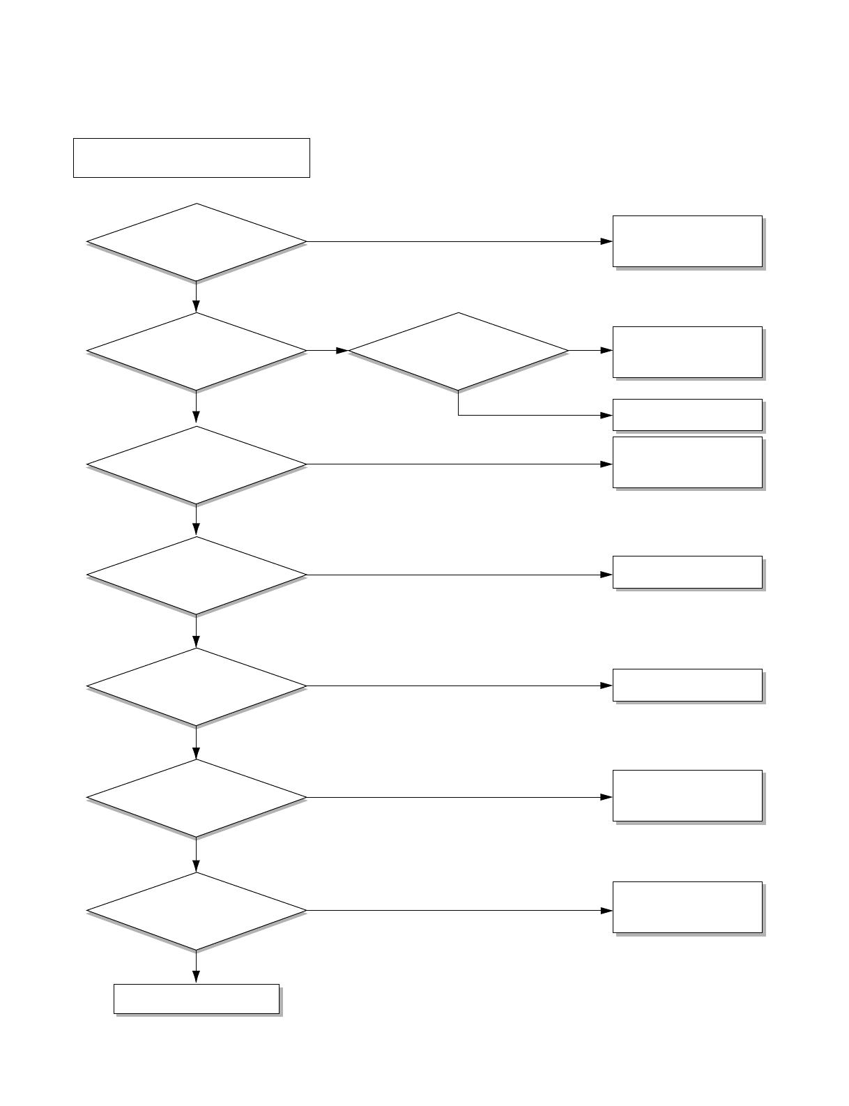
Is the Trans output power the
same as specified?
Is the Trans output power
about AC 14V?
Is shorted the Trans. output?
Is output Voltage of IC01D
DC 12V?
Is output Voltage of IC02D
DC 5V?
Is the voltage No.18 of Micom
DC 5V?
Exchange Main P.W.B Ass'y.
Is the
connection between
Main and Display
all right?
Is the reset circuit all right?
(The No.14 of Micom
is 5V.)
•
Check the Fuse.
•
Check the wiring diagram.
•
Check the Main
P.W.B pattern.
• Exchange the Trans.
•
Exchange D02D~D05D.
• Exchange IC01D.
• Exchange IC02D.
• Exchange IC01A.
• Connect connector
exactly.
• Check the
P.W.B
pattern.
NO
NO
NO
NO
NO
NO
NO
YES
YES
YES
YES
YES
YES
YES
NO
YES
ELECTRIC PARTS TROUBLESHOOTING GUIDE:
Possible Trouble 1
• The unit does not operate.
—20—
/