APC 100 User manual

Category
Uninterruptible power supplies (UPSs)
Type
User manual
990-1074B 01/2006
User Manual
English
APC Smart-UPS
®
1000/1500 VA
100/120/230 VAC
750/1000XL VA
120/230 VAC
Tower
Uninterruptible Power Supply
1
Introduction
American Power Conversion Corporation (APC) is the leading national and international manufac-
turer of state-of-the-art uninterruptible power supplies, redundant switches, power management soft-
ware, and related equipment. APC products protect hardware, software, and data from power distur-
bances in business and government offices throughout the world.
The APC Uninterruptible Power Supply (UPS) is designed to prevent blackouts, brownouts, sags,
and surges from reaching your computer and other valuable electronic equipment. The UPS filters
small utility line fluctuations and isolates your equipment from large disturbances by internally dis-
connecting from the utility line. The UPS provides continuous power from its internal battery until
the utility line returns to safe levels or the battery is discharged.
1: INSTALLATION
Read the Safety Instruction sheet before installing the UPS.
Unpacking
Inspect the UPS upon receipt. APC designed robust packaging for your product. However, accidents
and damage may occur during shipment. Notify the carrier and dealer if there is damage.
The packaging is recyclable; save it for reuse or dispose of it properly.
Check the package contents. The package contains the UPS, a literature kit containing one CD, one
serial cable, one USB cable, product documentation and Safety Information.
230V models: Two IEC jumper cables are included and a utility connector plug is included for use
on servers with permanently attached power cords.
The UPS is shipped with the battery disconnected.
Positioning the UPS
The UPS is heavy. Select a location sturdy enough to handle the weight.
Do not operate the UPS where there is excessive dust or the temperature and humidity are outside the
specified limits.
P
LACEMENT
2.5cm
(
1in
)
0º- 40ºC (32º-104ºF)
0-95% Relative
Humidity
2
Connecting Equipment and Power to the UPS
SMART-UPS REAR PANEL
230V
MODELS 120V/100V MODELS
1.
Plug in the battery connector n.
2. Connect equipment to the UPS. Note: Do not connect a laser printer to the UPS. A laser
printer draws significantly more power than other types of equipment and may overload
the UPS.
3. Add any optional accessories to the Smart-Slot Y.
4. Using the power cord, plug the UPS into a two-pole, three-wire, grounded receptacle only.
Avoid using extension cords.
230V models: A utility connector plug is included for use on servers with permanently at-
tached power cords.
120V/100V models: The power cord is permanently attached to the rear panel of the UPS.
5. Turn on all connected equipment. To use the UPS as a master ON/OFF switch, be sure all con-
nected equipment is switched ON. The equipment will not be powered until the UPS is turned
on.
6. To power up the UPS press the
button on the front panel.
The UPS charges its battery when it is connected to utility power. The battery charges to
90% capacity during the first three hours of normal operation. Do not expect full battery run
capability during this initial charge period.
120V Models: Check the site wiring fault LED located on the rear panel. It lights up if the
UPS is plugged into an improperly wired utility power outlet. Refer to Troubleshooting in
this manual.
7. For additional computer system security, install PowerChutePlus
®
UPS Power Management and
Diagnostic Software.
X
X
Y
Y
3
BASIC CONNECTORS
Serial Port
USB Port
Power management software and interface kits can be used
with the UPS. Use only interface kits supplied or approved
by APC.
Use the APC supplied cable to connect to the Serial Port. DO NOT use a standard
serial interface cable since it is incompatible with the UPS connector.
Both Serial and USB Ports are provided. They cannot be used simultaneously.
External Battery
Pack Connector
XL models: Use the battery pack connector to connect optional external
battery pack(s). These units support up to ten external battery packs.
See the APC web site, www.apc.com/support
for the correct external
battery pack model number for your UPS.
TVSS Screw
The UPS features a transient voltage surge-suppression (TVSS) screw for
connecting the ground lead on surge suppression devices such as tele-
phone and network line protectors.
When connecting grounding cable, disconnect the unit from the utility
power outlet.
4
2: OPERATION
SMART-UPS FRONT PANEL
Power On
Power Off
Load Battery Charge
Online
The online LED illuminates when the UPS is supplying utility power to the con-
nected equipment. If the LED is not lit, the UPS is either not turned ON, or is sup-
plying battery power.
AVR Trim
This LED illuminates to indicate the UPS is compensating for a high utility voltage.
5
AVR Boost
This LED illuminates to indicate the UPS is compensating for a low
utility voltage.
On Battery
When the on battery power LED is lit the UPS is supplying battery
power to the connected equipment. When on battery, the UPS sounds
an alarm—four beeps every 30 seconds.
Overload
The LED illuminates and the UPS emits a sustained alarm tone when
an overload condition occurs.
Replace Battery
Failure of a battery self-test causes the UPS to emit short beeps for
one minute and the replace battery LED illuminates. Refer to Trou-
bleshooting in this manual.
Battery
Disconnected
The replace battery LED flashes and short beep is emitted every two
seconds to indicate the battery is disconnected.
Automatic Self-Test
The UPS performs a self-test automatically when turned on, and every
two weeks thereafter (by default).
During the self-test, the UPS briefly operates the connected equip-
ment on battery.
If the UPS fails the self-test, the replace battery LED
lights and
immediately returns to online operation. The connected equipment is
not affected by a failed test. Recharge the battery for 24 hours and
perform another self-test. If it fails, the battery must be replaced.
Manual Self-Test
Press and hold the button for a few seconds to initiate the self-
test.
On Battery Operation
The Smart-UPS switches to battery operation automatically if the utility power fails. While running
on battery, an alarm beeps four times every 30 seconds.
Press the
button (front panel) to silence the UPS alarm (for the current alarm only. If the utility
power does not return, the UPS continues to supply power to the connected equipment until the bat-
tery is exhausted.
If PowerChute is not being used you must manually save your files and power down before the UPS
turns off.
D
ETERMINING ON BATTERY RUN TIME
UPS battery life differs based on usage and environment. It is recommended that the battery/batteries
be changed once every three years. See the APC web site, www.apc.com
, for on battery run times.
6
3: USER CONFIGURABLE ITEMS
NOTE: SETTINGS ARE MADE THROUGH SUPPLIED POWERCHUTE SOFTWARE OR OPTIONAL SMART SLOT
ACCESSORY CARDS.
FUNCTION
F
ACTORY
DEFAULT
U
SER SELECTABLE CHOICES DESCRIPTION
Automatic Self-Test Every 14 days
(336 hours)
Every 7 days
(168 hours),
On Startup Only, No Self-
Test
This function sets the inter-
val at which the UPS will
execute a self-test. Refer to
your software manual for
details.
UPS ID UPS_IDEN Up to eight characters to
define the UPS
Use this field to uniquely
identify the UPS, (ie. server
name or location) for net-
work management purposes.
Date of Last Battery Re-
placement
Manufacture
Date
Date of Battery Replacement
mm/dd/yy
Reset this date when you
replace the battery module.
Minimum Capacity Be-
fore Return from Shut-
down
0 percent 15, 30, 45, 50, 60, 75, 90
percent
The UPS will charge its
batteries to the specified
percentage before return
from a shutdown.
Voltage Sensitivity
The UPS detects and
reacts to line voltage
distortions by transferring
to battery operation to
protect the connected
equipment. Where power
quality is poor, the UPS
may frequently transfer to
battery operation. If the
connected equipment can
operate normally under
such conditions, reduce
the sensitivity setting to
conserve battery capacity
and service life.
Brightly lit: UPS is set to
high sensitivity (default).
Dimly lit: UPS is set to
medium sensitivity.
Off: Low battery
warning interval is about
eight minutes.
To change the UPS sensitiv-
ity, press the voltage sensi-
tivity button
(rear panel).
Use a pointed object (such as
a pen) to do so.
You can change the sensitiv-
ity level through Power-
Chute software.
Alarm Control Enable Mute, Disable User can mute an ongoing
alarm or disable all existing
alarms permanently.
Shutdown Delay 90 seconds 0, 180, 270, 360, 450, 540,
630 seconds
Sets the interval between the
time when the UPS receives
a shutdown command and
actual shutdown.
7
NOTE: SETTINGS ARE MADE THROUGH SUPPLIED POWERCHUTE SOFTWARE OR OPTIONAL SMART SLOT
ACCESSORY CARDS.
FUNCTION
F
ACTORY
DEFAULT
U
SER SELECTABLE CHOICES DESCRIPTION
Low Battery Warning.
PowerChute interface
software provides auto-
matic, unattended shut-
down when approxi-
mately two minutes (by
default) of battery oper-
ated run time remains.
Brightly lit: Low battery
warning interval is about two
minutes.
Dimly lit: Low battery
warning interval is about five
minutes.
Off: Low battery
warning interval is about
eight minutes.
Possible interval settings:
2, 5, 8, 11, 14, 17, 20, 23
minutes.
The low battery warning
beeps are continuous when
two minutes of run time
remain.
To change the warning in-
terval default setting, press
the voltage sensitivity button
(use a pointed object such as
a pen to do so), while press-
ing and holding the
button (front panel).
Synchronized Turn-on
Delay
0 seconds 60, 120, 180, 240, 300, 360,
420 seconds
The UPS will wait the speci-
fied time after the return of
utility power before turn-on
(to avoid branch circuit
overload).
High Transfer Point 230V models:
253VAC
120V models:
127VAC
100V models:
108VAC
230V models:
257, 261, 265VAC
120V models:
130, 133, 136VAC
100V models:
110, 112, 114VAC
To avoid unnecessary bat-
tery usage, set the high
transfer point higher if the
utility voltage is chronically
high and the connected
equipment is known to work
under this condition.
Low Transfer Point 230V models:
208VAC
120V models:
106VAC
100V models:
92VAC
230V models:
196, 200, 204VAC
120V models:
97, 100, 103VAC
100V models:
86, 88, 90VAC
Set the low transfer point
lower if the utility voltage is
chronically low and the con-
nected equipment can toler-
ate this condition.
Output Voltage 230V models:
230VAC
230V models:
220, 240VAC
230V models ONLY, allow
the user to select the output
voltage.
8
4: STORAGE, MAINTENANCE, AND TRANSPORTING
Storage
Store the UPS covered and positioned as for proper functioning, in a cool, dry location, with the bat-
teries fully charged.
At -15 to +30 °C (+5 to +86 °F), charge the UPS battery every six months.
At +30 to +45 °C (+86 to +113 °F), charge the UPS battery every three months.
Replacing the Battery Module
This UPS has an easy to replace, hot-swappable battery module. Replacement is a safe procedure,
isolated from electrical hazards. You may leave the UPS and connected equipment on for this proce-
dure. See your dealer or contact APC at the web site, www.apc.com/support
for information on re-
placement battery modules.
Once the battery is disconnected, the connected equipment is not protected from
power outages.
Be careful during the following steps-the battery module is heavy.
REMOVING THE FRONT BEZEL AND BATTERY MODULE
Step 1 Step 2
9
1500VA Model
Step 3
Pull the battery module out of the compartment
until the back of the module is flush with the
outer edges of the UPS.
Disconnect the battery connector.
1000VA Model
Step 3
Disconnect the battery cable terminals before
removing the battery module from the UPS.
Note: The red cable connects to the red color-
coded terminal; the black cable connects to the
black color-coded terminal. This will be impor-
tant during the battery replacement procedure.
Be sure to deliver the spent battery to a recycling facility or ship it to APC in the re-
placement battery packing material.
Battery
Terminals
Step B
Step A
Battery
Terminals
10
REPLACING THE BATTERY MODULE
To replace the battery module, reverse the directions above for Removing the Front Bezel and Bat-
tery Module.
Disconnecting the Battery for Transport
Always DISCONNECT THE BATTERY before shipping in compliance with U.S.
Department of Transportation (DOT) regulations.
The battery may remain in the UPS; it does not have to be removed.
1. Shut down and disconnect any equipment attached to the UPS.
2. Shut down and disconnect the UPS from the power supply.
3. Unplug the battery connector
(rear panel).
For shipping instructions and to obtain appropriate packing materials contact APC at the web site,
www.apc.com/support/contact
.
11
5: TROUBLESHOOTING
Use the chart below to solve minor Smart-UPS installation and operation problems. Refer to the APC
web site, www.apc.com
, for assistance with complex UPS problems.
PROBLEM AND POSSIBLE
CAUSE
S
OLUTION
UPS WILL NOT TURN ON
Battery not connected prop-
erly.
Check that the battery connector (rear panel) is fully engaged.
button not pushed. Press the button once to power the UPS and the connected equipment.
UPS not connected to utility
power supply.
Check that the power cable from the UPS to the utility power supply is se-
curely connected at both ends.
Very low or no utility voltage. Check the utility power supply to the UPS by plugging in a table lamp. If the
light is very dim, have the utility voltage checked.
UPS WILL NOT TURN OFF
Internal UPS fault. Do not attempt to use the UPS. Unplug the UPS and have it serviced imme-
diately.
UPS BEEPS OCCASIONALLY
Normal UPS operation. None. The UPS is protecting the connected equipment.
UPS DOES NOT PROVIDE EXPECTED BACKUP TIME
The UPS battery is weak due
to a recent outage or is near
the end of its service life.
Charge the battery. Batteries require recharging after extended outages.
They wear faster when put into service often or when operated at elevated
temperatures. If the battery is near the end of its service life, consider replac-
ing the battery even if the replace battery LED is not yet lit.
ALL LEDS ARE LIT AND THE UPS EMITS A CONSTANT BEEPING
Internal UPS fault. Do not attempt to use the UPS. Turn the UPS off and have it serviced imme-
diately.
FRONT PANEL LEDS FLASH SEQUENTIALLY
The UPS has been shut down
remotely through software or
an optional accessory card.
None. The UPS will restart automatically when utility power returns.
ALL LEDS ARE OFF AND THE UPS IS PLUGGED INTO A WALL OUTLET
The UPS is shut down and the
battery is discharged from an
extended outage.
None. The UPS will return to normal operation when the power is restored
and the battery has a sufficient charge.
12
PROBLEM AND POSSIBLE
CAUSE
S
OLUTION
THE OVERLOAD LED IS LIT AND THE UPS EMITS A SUSTAINED ALARM TONE
The UPS is overloaded. The connected equipment exceeds the specified “maximum load” as de-
fined in Specifications at the APC web site, www.apc.com.
The alarm remains on until the overload is removed. Disconnect nonessen-
tial equipment from the UPS to eliminate the overload.
The UPS continues to supply power as long as it is online and the circuit
breaker does not trip; the UPS will not provide power from batteries in the
event of a utility voltage interruption.
If a continuous overload occurs while the UPS is on battery, the unit turns
off output in order to protect the UPS from possible damage.
THE REPLACE BATTERY LED IS LIT
Replace Battery LED flashes
and short beep is emitted every
two seconds to indicate the
battery is disconnected.
Check that the battery connectors are fully engaged.
Weak battery. Allow the battery to recharge for 24 hours. Then, perform a self-test. If the
problem persists after recharging, replace the battery.
Failure of a battery self-test. The UPS emits short beeps for one minute and the replace battery LED
illuminates. The UPS repeats the alarm every five hours. Perform the self-
test procedure after the battery has charged for 24 hours to confirm the
replace battery condition. The alarm stops and the LED clears if the bat-
tery passes the self-test.
THE SITE WIRING FAULT LED IS LIT
The site wiring LED is lit
(rear panel).
120V models only.
The UPS is plugged into an improperly wired utility power outlet. Wiring
faults detected include missing ground, hot-neutral polarity reversal, and
overloaded neutral circuit. Contact a qualified electrician to correct the
building wiring.
THE INPUT CIRCUIT BREAKER TRIPS
The plunger on the circuit
breaker (located above the input
cable connection) pops out.
Reduce the load on the UPS by unplugging equipment and press the
plunger in.
AVR BOOST OR AVR TRIM LEDS LIGHT
AVR Boost or Trim LEDs light
Your system is experiencing
excessive periods of low r high
voltage.
Have qualified service personnel check your facility for electrical prob-
lems. If the problem continues, contact the utility company for further
assistance.
13
PROBLEM AND POSSIBLE
CAUSE
S
OLUTION
UTILITY CIRCUIT BREAKER TRIPS
Utility circuit breaker trips during
normal operation.
100V models: In order to operate at the full VA rating of the 1500VA
product, the supplied 15A plug must be replaced with a 20A plug. This
change must be performed by qualified service personnel.
UPS OPERATES ON BATTERY ALTHOUGH NORMAL LINE VOLTAGE EXISTS
UPS input circuit breaker tripped. Reduce the load on the UPS by unplugging equipment and resetting the
circuit breaker (on the back of UPS) by pressing the plunger in.
Very high, low, or distorted line
voltage. Inexpensive fuel powered
generators can distort the voltage.
Move the UPS to a different outlet on a different circuit. Test the input
voltage with the utility voltage display (see below). If acceptable to the
connected equipment, reduce the UPS sensitivity.
BATTERY CHARGE AND BATTERY LOAD LEDS FLASH SIMULTANEOUSLY
UPS has shutdown.
The internal temperature of the
UPS has exceeded the allowable
threshold for safe operation.
Check that the room temperature is within the specified limits for opera-
tion.
Check that the UPS is properly installed allowing for adequate ventila-
tion.
Allow the UPS to cool down. Restart the UPS. If the problem continues
contact APC at, www.apc.com/supoport
.
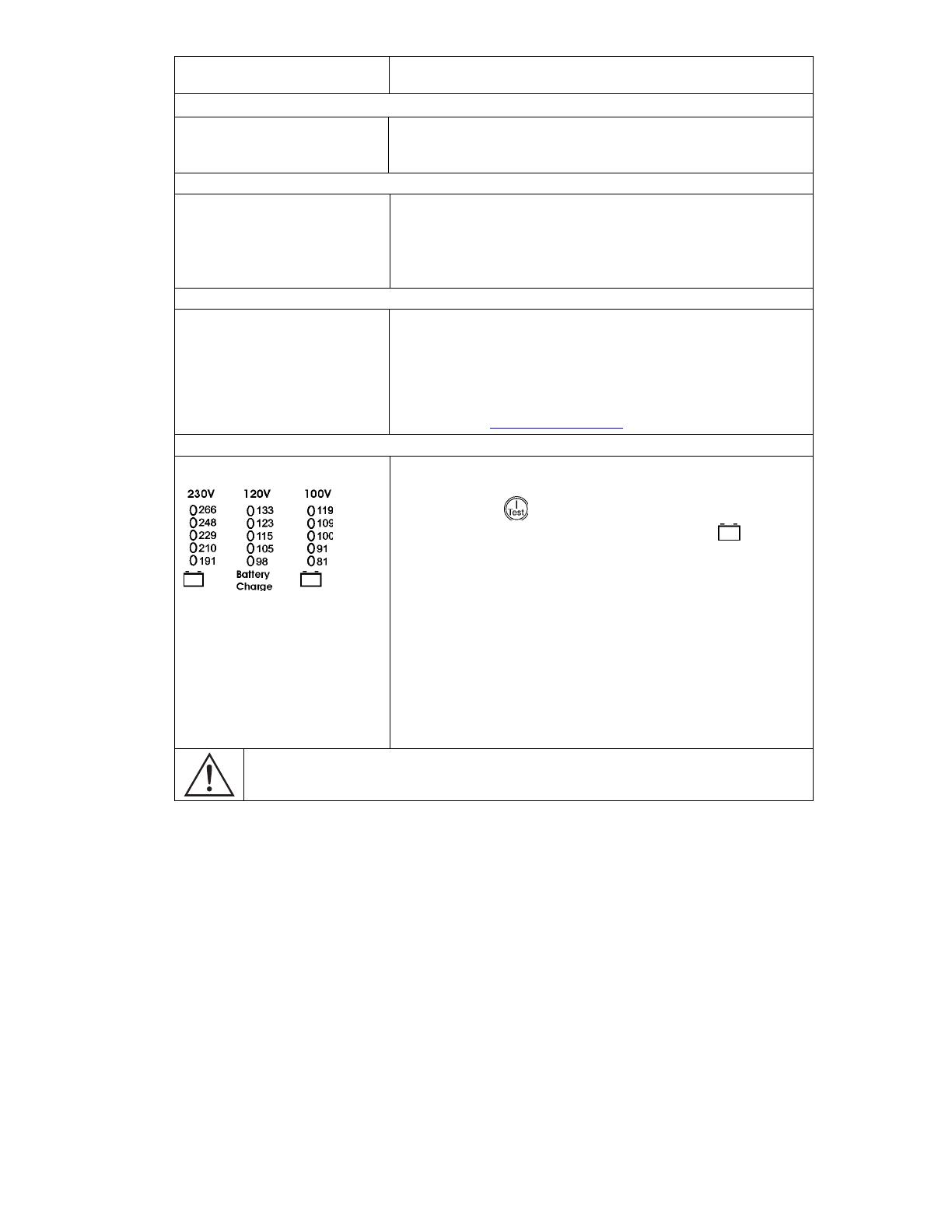
DIAGNOSTIC UTILITY VOLTAGE FEATURE
Utility Voltage
The UPS has a diagnostic feature that displays the utility voltage. Plug
the UPS into the normal utility power.
Press and hold the
button to view the utility voltage bar graph dis-
play. After a few seconds the five-LED, Battery Charge, , display
on the right of the front panel shows the utility input voltage.
Refer to the figure at left for the voltage reading (values are not listed on
the UPS).
The display indicates the voltage is between the displayed value on the
list and the next higher value.
Three LEDs light, indicating utility voltage within the normal range.
If no LEDs are lit and the UPS is plugged into a working utility power
outlet, the line voltage is extremely low.
If all five LEDs are lit, the line voltage is extremely high and should be
checked by an electrician.
The UPS starts a self-test as part of this procedure. The self-test does not affect the voltage dis-
play.
14
Service
If the UPS requires service do not return it to the dealer. Instead, follow these steps:
1. Review the problems discussed in the Troubleshooting section of this manual to eliminate com-
mon problems.
2. If the problem persists, contact APC Customer Service through the APC web site,
www.apc.com/support
.
Note the model number of the UPS, the serial number, and the date purchased. If you call
APC Customer Service, a technician will ask you to describe the problem and try to solve it
over the phone, if possible. If this is not possible, the technician will issue a Returned Mate-
rial Authorization Number (RMA#).
If the UPS is under warranty, repairs are free. If not, there is a repair charge.
3. Pack the UPS in its original packaging. If the original packing is not available, refer to the APC
web site, www.apc.com/support
, for information about obtaining a new set.
Pack the UPS properly to avoid damage in transit. Never use Styrofoam beads for packaging.
Damage sustained in transit is not covered under warranty.
Always DISCONNECT THE BATTERY before shipping in compliance with U.S.
Department of Transportation (DOT) regulations.
The battery may remain in the UPS; it does not have to be removed.
4. Mark the RMA# on the outside of the package.
5. Return the UPS by insured, prepaid carrier to the address given to you by Customer Service.
Contacting APC
Refer to the information provided at the APC Internet site,
http://www.apc.com/support
.
15
6: REGULATORY AND WARRANTY INFORMATION
Regulatory Agency Approvals and Radio Frequency Warnings
230V MODELS
This is a Class A product. In a domestic environment
this product may cause radio interference, in which
case the user may be required to take corrective ac-
tions.
120V MODELS
This equipment has been tested and found to comply with the limits for a Class A digital device, pursuant to part 15 of the
FCC Rules. These limits are designed to provide reasonable protection against harmful interference when the equipment is
operated in a commercial environment. This equipment generates, uses, and can radiate radio frequency energy and, if not
installed and used in accordance with the instruction manual, may cause harmful interference to radio communications.
Operation of this equipment in a residential area is likely to cause harmful interference in which case the user will be re-
quired to correct the interference at his own expense.
Shielded signal cables must be used with this product to ensure compliance with the Class A FCC limits.
100V
MODELS
16
Declaration of Conformity
Limited Warranty
American Power Conversion (APC) warrants its products to be free from defects in materials and workmanship for a period of
two years from the date of purchase. Its obligation under this warranty is limited to repairing or replacing, at its own sole op-
tion, any such defective products. To obtain service under warranty you must obtain a Returned Material Authorization
(RMA) number from customer support. Products must be returned with transportation charges prepaid and must be accompa-
nied by a brief description of the problem encountered and proof of date and place of purchase. This warranty does not apply
to equipment that has been damaged by accident, negligence, or misapplication or has been altered or modified in any way.
This warranty applies only to the original purchaser who must have properly registered the product within 10 days of pur-
chase.
EXCEPT AS PROVIDED HEREIN, AMERICAN POWER CONVERSION MAKES NO WARRANTIES, EXPRESSED OR
IMPLIED, INCLUDING WARRANTIES OF MERCHANTABILITY AND FITNESS FOR A PARTICULAR PURPOSE.
Some states do not permit limitation or exclusion of implied warranties; therefore, the aforesaid limitation(s) or exclusion(s)
may not apply to the purchaser.
EXCEPT AS PROVIDED ABOVE, IN NO EVENT WILL APC BE LIABLE FOR DIRECT, INDIRECT, SPECIAL, INCI-
DENTAL, OR CONSEQUENTIAL DAMAGES ARISING OUT OF THE USE OF THIS PRODUCT, EVEN IF ADVISED
OF THE POSSIBILITY OF SUCH DAMAGE. Specifically, APC is not liable for any costs, such as lost profits or revenue,
loss of equipment, loss of use of equipment, loss of software, loss of data, costs of substitutes, claims by third parties, or oth-
erwise.
Entire contents copyright 2001 by American Power Conversion Corporation. All rights reserved. Reproduction in whole or in
part without permission is prohibited.
APC, Smart-UPS, and PowerChute are registered trademarks of American Power Conversion Corporation.
All other trademarks are the property of their respective owners.
  • Page 1 1
  • Page 2 2
  • Page 3 3
  • Page 4 4
  • Page 5 5
  • Page 6 6
  • Page 7 7
  • Page 8 8
  • Page 9 9
  • Page 10 10
  • Page 11 11
  • Page 12 12
  • Page 13 13
  • Page 14 14
  • Page 15 15
  • Page 16 16
  • Page 17 17
  • Page 18 18

APC 100 User manual

Category
Uninterruptible power supplies (UPSs)
Type
User manual

Ask a question and I''ll find the answer in the document

Finding information in a document is now easier with AI