Page is loading ...

Questions, problems, missing parts? Before returning to your retailer, call our customer
service department at 1-800-643-0067, 8 a.m. - 6 p.m., EST, Monday - Thursday, 8 a.m. - 5 p.m.,
EST, Friday.
1
Lowes.com/harborbreeze
Harbor Breeze® is a registered trademark
of LF, LLC. All Rights Reserved.
ATTACH YOUR RECEIPT HERE
Serial Number _________________________ Purchase Date _________________________
ITEM #0184428
KINGSBURY CEILING FAN
MODEL #40190
Español p. 23
EB13357

2
Lowes.com/harborbreeze
TABLE OF CONTENTS
Package Contents .................................................................3
Hardware Contents ................................................................4
Safety Information .................................................................5
Preparation ......................................................................6
Initial Installation ..................................................................7
Wiring .........................................................................13
Final Installation. . . . . . . . . . . . . . . . . . . . . . . . . . . . . . . . . . . . . . . . . . . . . . . . . . . . . . . . . . . . . . . . . . 14
Operating Instructions .............................................................17
Care and Maintenance ............................................................18
Troubleshooting ..................................................................18
Limited Lifetime Warranty ..........................................................21
Replacement Parts List ............................................................22

3
Lowes.com/harborbreeze
PACKAGE CONTENTS
A
E
I
M
B
F
J
C
G
K
D
H
L
2
+
+
H
N
O
PART DESCRIPTION QUANTITY
A Downrod 1
B Canopy (preassembled to Mounting Bracket (C)) 1
C Mounting Bracket 1
D Light Kit Fitter 1
E Motor Assembly 1
F Yoke Cover 1
G Blade Arm 5
H Blade 5
I Glass Shade 1
J Bulb 2
K Canopy Cover ((preassembled to Canopy (B)) 1
L Light Kit Plate 1
M Remote Control 1
N Wall Bracket Assembly 1
O Battery 1

4
Lowes.com/harborbreeze
HARDWARE CONTENTS
Motor Screw
Qty. 10
+ 1 extra
Blade Screw
Qty. 15
+ 1 extra
Blade Washer
Qty. 15
+ 1 extra
Wire Connector
Qty. 3
+ 1 extra
Downrod Pin
Qty. 1
(preassembled to
Downrod (A))
Downrod Clip
Qty. 1
(preassembled to
Downrod (A))
Motor Housing Set Screw
Qty. 2
(preassembled to Motor
Assembly (E))
Mounting Bracket Screw
Qty. 4
(preassembled to Mounting
Bracket (C))
Fitter Plate Screw
Qty. 4
(preassembled to
Motor Assembly (E))
Light Plate Screw
Qty. 3
(preassembled to
Light Kit Plate (L))
Closemount Screw
Qty. 3
+ 1 extra
AA
EE
BB
FF
CC
GG
KKJJII
DD
HH
(shown actual size)

5
Lowes.com/harborbreeze
SAFETY INFORMATION
Please read and understand this entire manual before attempting to assemble, operate or install the
product.
• Before you begin installing the fan, disconnect the power by removing fuses or turning off the circuit
breakers.
• Make sure that all electrical connections comply with local codes, ordinances, the National
ElectricalCode,andANSI/NFPA70-199.Hireaqualiedelectricianorconsultado-it-yourself
wiring handbook if you are unfamiliar with installing electrical wiring.
• Make sure the installation site you choose allows a minimum clearance of 7 ft. from the blades to
theoorandatleast30in.fromtheendofthebladestoanyobstruction.
• The net weight of this fan is: 23.65 lbs.
DANGER: When using an existing outlet box, make sure the outlet box is securely attached to
the building structure and can support the full weight of the fan. Failure to do this can result in serious
injury or death. The stability of the outlet box is essential in minimizing wobble and noise in the fan
after installation is complete.
WARNING: To avoid personal injury, the use of gloves may be necessary while handling fan
parts with sharp edges.
WARNING: Using a full-range dimmer switch to control fan speed will cause a loud humming
noisefromthefan.Toreducetheriskofreorelectricshock,doNOTuseafull-rangedimmerswitch
to control the fan speed.
WARNING: Toreducetheriskofre,electricshockorpersonalinjury,mountthefantoan
outlet box marked “ACCEPTABLE FOR FAN SUPPORT” and use the mounting screws provided with
theoutletbox.Mostoutletboxescommonlyusedforthesupportoflightingxturesarenotacceptable
forfansupportandmayneedtobereplaced.Consultaqualiedelectricianifindoubt.Securethe
outlet box directly to the building structure. The outlet box and its support must be able to support the
moving weight of the fan (at least 35 lbs.). Do NOT use a plastic outlet box.
WARNING: Toreducetheriskofre,electricalshockorpersonalinjury,wireconnectors
provided with this fan are designed to accept only one 12-gauge house wire and two lead wires from
the fan. If your house wire is larger than 12 gauges or there is more than one house wire to connect
to the two fan lead wires, consult an electrician for the proper size wire connectors to use.
WARNING: Toreducetheriskofreorelectricshock,donotusethefanwithanysolid-state
speed-control device or control the fan speed with a full-range dimmer switch.
WARNING: Toreducetheriskofre,electricshock,orpersonalinjury,donotbendtheblade
arms when installing them, balancing the blades or cleaning the fan. Do not insert objects between
the rotating fan blades.
WARNING: To reduce the risk of personal injury, use only parts provided with this fan. The use
of parts OTHER than those provided with this fan will void the warranty.

6
Lowes.com/harborbreeze
SAFETY INFORMATION
CAUTION: Read all instructions and safety information before installing your new fan. Review the
accompanying assembly diagrams.
CAUTION: Be sure the outlet box is properly grounded or that a ground (green or bare) wire is present.
CAUTION: Carefully check all screws, bolts, and nuts on the fan motor assembly to ensure that they
are secured.
CAUTION: This equipment has been tested and found to comply with the limits for a Class B digital
device, pursuant to Part 15 of the FCC Rules. These limits are designed to provide reasonable
protection against harmful interference in a residential installation. This equipment generates,
uses and can radiate radio frequency energy and, if not installed and used in accordance with the
instructions, may cause harmful interference to radio communications.
PREPARATION
Before beginning the assembly of this product, ensure that all parts are present. Compare all parts
with the package contents list and hardware contents list. If any part is missing or damaged, do not
attempt to assemble the product.
After opening the top of the carton, remove the mounting hardware package from the foam inserts,
then remove the motor from the packaging and place it on a soft surface, such as a carpet, to avoid
damagetothenish.
Estimated Assembly Time: 120 minutes
Tools Required for Assembly (not included): Electrical Tape, Phillips Screwdriver, Pliers, Safety
Glasses, Step Ladder, and Wire Strippers
Helpful Tools (not included): AC Tester Light, Tape Measure, Wiring Handbook, and Wire Cutters
LAMP CONTAINS MERCURY
LA BOMBILLA CONTIENE MERCURIO
Manage in accordance with Spills, Disposal and Site Cleanup
Requirements. In case of breakage, follow clean-up
procedures provided by contacts below.
Manipule según las exigencias sobre derrames, eliminación y
limpieza del lugar. En caso se rompa, siga el método de
limpieza proporcionado por los siguientes contactos.
Hg
www.epa.gov/ccleanup
1-866-284-4010

7
Lowes.com/harborbreeze
INITIAL INSTALLATION
1. Turn off the circuit breakers and the wall switch to the
fan supply line leads.
DANGER: Failure to disconnect the power
supply prior to installation may result in serious injury
or death.
1
2. Determine the mounting method to use.
Note: Flushmount installation is not available for this
item.
Important: If using the angle mount, check to ensure
the ceiling angle is not steeper than 23°.
2
Downrod Mounting
Flushmount Closemount
Angle Mounting
3. Ensure the blades (H) will be at least 30 in. from any
obstructions. Also check the downrod (A) length to
ensure the blades (H) will be at least 7 ft. above the
oor.
H
A
3
7 ft.
Minimum
30 in.
Minimum

8
Lowes.com/harborbreeze
INITIAL INSTALLATION
4. Remove the two mounting bracket screws (HH)
from the round holes of canopy (B). Set aside
for later use. Detach mounting bracket (C) from
canopy (B), then attach mounting bracket (C) to
outlet box (not included) using screws and washers
provided with the outlet box.
Note: It is very important you use the proper
hardware when installing the mounting bracket (C) as
this will support the fan.
Important: If using the angle mount, ensure the
open end of the mounting bracket (C) is installed
facing the higher point of the ceiling.
Hardware Used
HH
Mounting
Bracket Screw
x 2
5. Remove and discard the cardboard shipping
material from the motor assembly (E).
C
4
B
HH
C
Cardboard
5
E

9
Lowes.com/harborbreeze
STANDARD OR ANGLE MOUNTING INSTRUCTIONS
1. Remove the downrod pin (EE) and downrod clip
(FF) from the downrod (A). Then partially loosen the
motor housing set screws (GG) in the yoke at the top
of the motor housing (E).
Helpful Hint: Standard mounting is best suited for
ceilings 8 ft. or higher. For taller ceilings you may
want to use a longer downrod (not included). Angle
mounting is best suited for angled or vaulted ceilings.
A longer downrod is sometimes necessary to ensure
proper blade clearance.
Hardware Used
EE
Downrod Pin x 1
FF
Downrod Clip x 1
GG
Motor Housing
Set Screw
x 2
E
A
EE
FF
GG
A
1
2. Insert the downrod (A) through the canopy (B) and
yoke cover (F). Thread the wires from the motor
assembly (E) through the downrod (A).
2
B
K
F
E
A

10
Lowes.com/harborbreeze
STANDARD OR ANGLE MOUNTING INSTRUCTIONS
3. Slide the downrod (A) into the yoke of the motor
assembly (E), align the holes, then re-install the
downrod clip (FF) and downrod pin (EE). Secure
with motor housing set screws (GG) and slide the
yoke cover (F) down until it rests on top of the motor
assembly (E).
Hardware Used
EE
Downrod Pin x 1
FF
Downrod Clip x 1
GG
Motor Housing
Set Screw
x 2
F
E
FF
GG
A
EE
3
4. Depending on the length of downrod you use, you
may need to cut the lead wires back to simplify the
wiring. If you decide to cut back the lead wires, it is
suggested you do so in the following manner: Take
the lead wires and make sure you have pulled them
all the way through the top of the downrod. Measure
8 inches of lead wire, then cut the excess wire off
with wire cutters (not included).
4

11
Lowes.com/harborbreeze
STANDARD OR ANGLE MOUNTING INSTRUCTIONS
5. If you decided to cut back the lead wire in Step 4,
strip 1/2 in. of insulation from the end of the white
wire. Twist the stripped ends of each strand of wire
within the insulation with pliers (not included). Repeat
the step for black and green wires.
Note: If you did not cut back the lead wires in Step
4, Step 5 is not necessary and you may proceed to
Step 6 instead.
5
6. Install the ball end of the downrod (A) into the opening
of the mounting bracket (C). Align the slot in the ball
with the tab in the mounting bracket (C). Note: The rod
should not rotate if it is done correctly.
DANGER: Failure to align the slot in the ball
with the tab may result in serious injury or death.
Proceed to the Wiring on page 13.
C
A
6

12
Lowes.com/harborbreeze
CLOSEMOUNT INSTRUCTIONS
1. Remove the canopy cover (K) from the bottom of the
canopy (B).
Helpful Hint: Closemount-style mounting is more
suitable for ceilings lower than 8 ft. high. The
downrod, hanging ball and canopy cover are not
used in this type of installation.
1
K
B
2. Align the canopy (B) with the holes in the top of the
motor assembly (E). Reinstall the closemount screws
(KK) to secure the canopy (B) to the top of the motor
assembly (E).
Hardware Used
KK
Closemount Screw x 3
E
B
KK
2
3. Raise the fan and place the canopy (B) on the hook
on the mounting bracket (C).
B
C
3

13
Lowes.com/harborbreeze
WIRING
WARNING:Toreducetheriskofre,electricalshock,orpersonalinjury,wireconnectors
provided with this fan are designed to accept only one 12 gauge house wire and two lead wires from
the fan. If your house wire is larger then 12 gauges and there is more than one house wire to connect
to the two fan lead wires, consult an electrician for the proper size wire connectors to use.
CAUTION: Be sure the outlet box is properly grounded or that a ground (green or bare) wire is present.
1. Connect supply and fan wires according to the
diagram and these steps:
•ConnecttheGreenwiresfromthefanandthe
mounting bracket (C) to the Bare/Green (ground)
supply wire.
•ConnecttheWhitewirefromthefantotheWhite
supply wire.
•ConnecttheBlackwirefromthefantotheBlack
supply wire.
•Secureallwiringconnectionstogetherwithwire
connectors (DD).
Note: The Black wire is hot power for the fan. The
White wire is common for the fan and light kit.
The Green wire is the ground wire. If house wires
are different colors than referred to above, stop
immediately. It is recommended a professional
electrician determines the proper wiring.
Hardware Used
DD
Wire Connector x 3
BLACK
WHITE
BARE/GREEN
GREEN
WHITE
BLACK
FAN
WHITE
1
2. Wrap electrical tape (not included) around each
individual wire connector (DD) down to the wire.
DD
DD
DD
2

14
Lowes.com/harborbreeze
WIRING
3. Turn the spliced/taped wires upward and gently push
the wires and wire connectors (DD) into the outlet
box.
WARNING: Ensure no bare wire or wire
strands are visible after making connections. Place
the Green and White wire connections on the
opposite side of the outlet box from the Black.
DD
3
FINAL INSTALLATION
1. Align the canopy (B) over the loose mounting bracket
screws (HH) preassembled on mounting bracket
(C). Place the keyholes of the canopy (B) onto the
mounting bracket screws (HH) and rotate the canopy
(B) clockwise.
Hardware Used
HH
Mounting Bracket
Screw
x 2
B
CH
H
1
2. Secure the canopy (B) with the mounting bracket
screws (HH) previously removed (Step 4, page 8).
Tighten all mounting bracket screws (HH) securely.
Hardware Used
HH
Mounting Bracket
Screw
x 4
B
HH
A
2
HH
Note: Closemount installation does
not use the downrod (A).

15
Lowes.com/harborbreeze
FINAL INSTALLATION
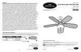
3. Partially insert three blade screws (BB), along with
three blade washers (CC) through one blade (H)
and into one blade arm (G). Tighten each blade
screw (BB) with a Phillips screwdriver (not included),
starting with the one in the middle. Repeat this step
for the remaining blades (H) and blade arms (G).
Hardware Used
BB
Blade Screw x 15
CC
Blade Washer x 15
BB
H
G
CC
H
3
4. Insert blade arm (G) through slots in the side of the
motor assembly (E). Align the holes of one blade
arm (G) with two motor screw holes in underside
of the motor assembly (E). Secure with two motor
screws (AA). Repeat this step for the remaining
blade arms (G).
Hardware Used
AA
Motor Screw x 10
GG
E
AA
4
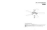
5. Removeoneofthefourtterplatescrews(II)located
on the underside of the motor assembly (E) and
loosen the other three screws. Align the screw holes
ofthelightkitplate(L)withtheloosenedtterplate
screws(II).Replacepreviouslyremovedtterplate
screw (II), then tighten all screws.
Hardware Used
II
Fitter Plate
Screw
x 4
L
II
E
5

16
Lowes.com/harborbreeze
FINAL INSTALLATION
6. Remove one of the three light plate screws (JJ) from
the light kit plate (L) and loosen the other two screws.
Connect the wire connectors (white to white and
black to black) from the motor assembly (E) to the
lightkittter(D).Alignthescrewholesofthelightkit
tter(D)withtheloosenedlightplatescrews(JJ)and
replace previously removed lit kit plate screw (JJ).
Tighten all screws.
Hardware Used
JJ
Light Kit Plate
Screw
x 3
D
JJ
E
L
6
7. Installbulbs(J)intothesocketsonthelightkittter(D).
Important: Make sure you allow the bulbs (J) and
light kit to cool before you replace the bulbs.
JJ
D
7
8. Attach the glass shade (I) to the light kit plate (L)
by twisting the glass shade (I) tightly in a clockwise
direction.
I
L
8

17
Lowes.com/harborbreeze
OPERATING INSTRUCTIONS
1. To operate the fan using remote control (M), press
and release the following buttons:
Speed Control - Controls fan speed 1 (low) - 6 (high).
Fan On/Off - Turns fan off or turns fan on at most
recently selected speed. Press and hold to turn off or
on the sounds from the remote control.
Variable Breeze - Simulates a natural breeze, as if
you were outside. Press any speed control button to
exit this mode.
Random Light - When button is pressed, light blinks
twicetoconrmRandomLightmode.Lightscycle
on for 5-20 minutes and off for 60 minutes. Cycle
repeats continuously until any other button is pushed
to discontinue Random Light mode.
Sleep Timer - Turns fan off after (2H) 2 hours, (4H) 4
hours or (8H) 8 hours.
Light On/Off - Turns light off or on.
Delayed Light Off - Delays turning off light for 1
minute which allows safe exit from room.
Season Slide Switch - Changes direction of blade
rotation. For warm weather slide switch to the left
and for cool weather slide switch to the right.
2. Remove battery door from back of the remote control
(M) to access the following:
DIP Switch - Changes signal frequency if
there is interference from another remote (see
troubleshooting for instructions).
Learn - Syncs remote control (M) to receiver (see
troubleshooting for instructions).
Battery Compartment - When necessary, replace
the pre-installed battery (O) with a new 12-volt
battery.
3. Remote control (M) comes equipped with a wall bracket
(N). If you wish to install the wall bracket (N), remove
the small plate to expose the screw holes. Insert wall
brackets screws through holes and into wall, then
cover with the previously removed small plate. Remote
control (M) sits inside the wall bracket (N).
Random Light
Light On/Off
Delayed Light Off
Speed
Control (1-6)
Fan On/Off
Variable Breeze
SleepTimer
Season Slide Switch
2
+
+
H
M
12V
2
DIP Switch
Battery Compartment
Learn Button
O
M
1
Wall Bracket
Screws
Small Plate
M
3
N

18
Lowes.com/harborbreeze
CARE AND MAINTENANCE
At least twice each year, lower the canopy to check the downrod assembly, and then tighten all
screws on the fan. Clean the motor housing with only a soft brush or lint-free cloth to avoid scratching
thenish.Cleanthebladeswithalint-freecloth.Youmayoccasionallyapplyalightcoatoffurniture
polish to wood blades for added protection.
Bulb Replacement: Use 13-watt max. GU24 bi-pin base CFL bulbs.
Important: Shut off the main power supply before you begin any maintenance tasks. Do not use
water or a damp cloth to clean the ceiling fan.
TROUBLESHOOTING
PROBLEM POSSIBLE CAUSE CORRECTIVE ACTION
The fan does not
move.
1. The power is off or the fuse is
blown.
2. There is a faulty wire connection.
3. The plugs are not connected
properly.
4. The DC motor is obstructed
during operation.
5. The power of the motor is over
80W.
1. Turn the power on or check the
fuse.
2. Turn the power off. Loosen
the canopy and check all
connections.
3. Check that the connectors from
thelightkittterandfanare
connected properly.
4. Disable the power supply to the
fan motor and re-start the motor.
5. The blade is overweight. Do not
install the unapproved blades.
The fan is noisy.
1. The blades are loose.
2. There is a cracked blade.
3. The wall control is not compatible
with the fan.
4. The break-in period has not
surpassed.
5. The outlet box is not secure.
6. The mounting bracket is not
secure.
1. Check and tighten all screws
that hold the fan blades to the
blade arms and the motor.
2. Replace the cracked blade.
3. Do not use a full range dimmer
switch to control the fan speed.
4. Run the fan continuously for 24
- 48 hours on medium or high
speed for a break-in period.
5. Ensure the outlet box is secured
to the building structure.
6. Ensure the mounting bracket is
secured to the outlet box and
that the screws are tight.

19
Lowes.com/harborbreeze
TROUBLESHOOTING
PROBLEM POSSIBLE CAUSE CORRECTIVE ACTION
There is excessive
wobbling.
1. The blades and/or blade are
loose.
2. The blades are unbalanced.
3. The fan mounting is not
secure.
4. The fan is too close to the
vaulted ceiling.
5. The set screw on the motor
housing yoke is loose.
1. Check and tighten all screws that hold
the fan blades to the blade arms and
the blade arms to the motor.
2. Switch one blade with a blade from
the opposite side. Or balance the fan
using a balancing kit (not supplied).
3. Turn off the power. Loosen the
canopy and verify that the mounting
bracket is secure to the electrical
outletbox.Thebracketmustbeush
without movement against the outlet
box.
4. Use a longer downrod or move the
fan to another location.
5. Lift up the yoke cover and tighten the
set screw to the yoke until secure.
The fan operates
correctly, but the
lights are not
working.
1. The bulbs are not installed
correctly.
2. The light kit wire plugs are
not connected properly.
3. There is a faulty wire
connection.
4. The total power of the light is
exceeding 190W.
1. Re-install the bulb(s).
2. Ensure that the male and female
plugsinthelightkittterare
connected properly.
3. Turn the power off and check all
connections at the ceiling outlet box.
4. The fan comes with a 190W limiter.
When the total watts of the lights is
over 190W, the lights do not work.
Please replace the bulbs with lower
wattage bulbs.

20
Lowes.com/harborbreeze
TROUBLESHOOTING
PROBLEM POSSIBLE CAUSE CORRECTIVE ACTION
Remote
control does
not work.
1. The power to the fan is off or the fuse
is blown.
2. Power surge may have cleared
memory and remote needs to be re-
synced to the receiver.
3. Battery in remote control needs to be
replaced.
4. Interference from another remote.
1. Turn the power on or check the
fuse.
2. Turn power to fan off and back
on. Within 30 seconds press the
LEARN button on back of remote
control (see p. 17).
3. Insert new 12V battery in battery
compartment of the remote control
(see p. 17).
4. The remote control has been
synced to this fan at the factory
and the dip switch as been
switched to “0” inside the battery
compartment. If you have more
than one remote control in the
room, you may need to change the
dip switch settings as follows:
Slide the dip switch to “1” inside
the battery compartment and turn
the power to the fan OFF Then
turn the power ON and you should
hear the remote receiver make two
musical sounds, indicating that
the power supply is normal. Within
30 seconds, press the “LEARN”
key on the back of the transmitter.
Your remote and fan should be
synchronized. To verify successful
synchronization, the ceiling fan
light (if installed) will blink 3 times
and remain ON, and the fan will
rotate on HIGH speed.
/