Honeywell MS9590 VoyagerGS User guide
- Category
- Bar code readers
- Type
- User guide

METROLOGIC INSTRUMENTS, INC.
MS9590 VoyagerGS
™
Series
Single-Line Hand Held Laser Scanner
Installation and User's Guide

Copyright
© 2008 by Metrologic Instruments, Inc. All rights reserved. No part of this
work may be reproduced, transmitted, or stored in any form or by any means
without prior written consent, except by reviewer, who may quote brief
passages in a review, or provided for in the Copyright Act of 1976.
Trademarks
Metrologic is a registered trademark of Metrologic Instruments, Inc.
Products identified in this document are hereby acknowledged as
trademarks, registered or otherwise, of Metrologic Instruments, Inc. or their
respective companies.

ii
TABLE OF CONTENTS
Introduction
Product Overview ............................................................................................. 1
Scanner and Accessories................................................................................. 2
Scanner Components....................................................................................... 4
Cable Installation and Removal........................................................................ 5
Labels............................................................................................................... 6
Scanner Installation
RS232 (-14)...................................................................................................... 7
RS485 (-106).................................................................................................... 8
Keyboard Wedge (-47) ..................................................................................... 9
Stand-Alone Keyboard (-47)........................................................................... 10
USB (-38 and -106) ........................................................................................ 11
Additional Settings for EAS Equipped Models................................................ 12
Stands
Flex Stand (PN 46-00709)
Components ............................................................................................... 13
Assembly.................................................................................................... 14
Optional Fixed Mount ................................................................................. 15
Optional Wall/Tabletop Stand (PN 46-00885)
Optional Fixed Mount ................................................................................. 16
Scanner Operation
Default Modes of Operation............................................................................ 17
Scanning with the Manual Activation Mode.................................................... 17
Maintenance................................................................................................... 17
Indicators
Audible ........................................................................................................... 18
Visual ............................................................................................................. 19
Failure Modes................................................................................................. 20

iii
TABLE OF CONTENTS
Configuration Modes .......................................................................................... 21
Upgrading the Flash ROM Firmware.................................................................. 22
Depth of Field
MS9590.......................................................................................................... 23
MS9591.......................................................................................................... 24
IR Activation Range
MS9590.......................................................................................................... 25
MS9591.......................................................................................................... 25
Applications and Protocols ................................................................................. 26
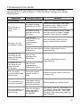
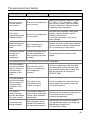
Troubleshooting Guide ....................................................................................... 27
Design Specifications
Operational..................................................................................................... 30
Mechanical ..................................................................................................... 31
Electrical......................................................................................................... 31
Environmental ................................................................................................ 31
Scanner and Cable Terminations
Scanner Pinout Connections.......................................................................... 32
Cable Connector Configurations .................................................................... 33
Limited Warranty ................................................................................................ 35
Regulatory Compliance
Safety ............................................................................................................. 36
EMC ............................................................................................................... 37
Patents ............................................................................................................... 39
Index .................................................................................................................. 40
Contact Information and Office Locations........................................................... 42

1
INTRODUCTION
Product Overview
The MS9590 VoyagerGS™ series is part of Metrologic’s extensive Voyager
®
branded hand-held laser scanning product family. The VoyagerGS series is the
first Voyager
®
product to feature trigger scanning in its design. The VoyagerGS
provides an aggressive solution for scanning all standard 1D bar codes in a new
ergonomic form factor that maximizes comfort and reduces fatigue.
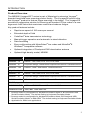
Key product features include:
• Rapid scan speed of 100 scans per second
• Extended depth of field
• CodeGate
®
data transmission technology
• Manual-trigger operation and automatic in-stand detection
• Data formatting
• Easy configuration with MetroSelect
®
bar codes and MetroSet
®
2
Windows
®
compatible software
• Optional integration of Checkpoint EAS deactivation antenna
• Optional high-density model, MS9591
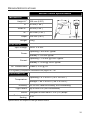
MODEL INTERFACE
MS9590 – 14 RS232 - TXD, RXD, RTS, CTS, DTR, DSR
MS9590 – 47 Keyboard Wedge, Stand-Alone Keyboard and RS232 Transmit/Receive
MS9590 – 106 RS485
, USB** and RS232 Transmit/Receive
High Density Models
MS9591– 14 RS232 - TXD, RXD, RTS, CTS, DTR, DSR
MS9591 – 47 Keyboard Wedge, Stand-Alone Keyboard and RS232 Transmit/Receive
MS9591 – 106 RS485
, USB** and RS232 Transmit/Receive
EAS Equipped Models
MS9590-38-EAS USB* and RS232 Transmit/Receive with EAS
MS9590-40-EAS USB, IBM
OEM with EAS
* Scanner model is configurable for Keyboard Emulation Mode or Bi-Directional USB
Serial Emulation Mode. The default setting is Keyboard Emulation Mode.
** Scanner model is configurable for Keyboard Emulation Mode, Bi-Directional USB
Serial Emulation Mode, or IBM OEM. The default setting is Keyboard Emulation Mode.
Applicable for IBM
®
host applications

2
INTRODUCTION
Scanner and Accessories
BASIC KIT
Part # Description
MS9590
or
MS9591
MS9590 Bar Code Scanner
or
MS9591 High-Density Bar Code Scanner
00-02544 MetroSelect Single-Line Configuration Guide
00-05150
MS9590 Series Single-Line Hand Held Laser Scanner
Installation and User’s Guide
Available for download at www.metrologic.com/corporate/download
OPTIONAL ACCESSORIES
Part # Description
46-00709 Flex Stand
46-00885 Wall Mount
AC to DC Power Transformer- Regulated 5.2VDC @ 1A output.
46-00525 90VAC to 255VAC, United States, Canada and Japan
46-00526 90VAC to 255VAC, Continental European
46-00870 90VAC to 255VAC, United Kingdom
46-00528 90VAC to 255VAC, Australia
46-00529 90VAC to 255VAC, China
Other items may be ordered for the specific protocol being used. To order additional items,
contact the dealer, distributor, or call Metrologic’s Customer Service Department at
1-800-ID-METRO or 1-800-436-3876.

3
INTRODUCTION
Scanner and Accessories
OPTIONAL ACCESSORIES
Part # Description
Cable Compatibility Warning
Use only MS9590 series compatible product cables from the list below.
Damage may occur to the scanner if incompatible cables are used.
Any damage incurred from incorrect cable usage will void the limited
warranty shown on page 35.
53-53000x-3
RS232 PowerLink Cable with Built in Power Jack
Black Coiled Cord with Long Strain Relief
53-53802x-N-3
Keyboard Wedge Cable with Adapter Cable
Black Coiled Cord with Long Strain Relief
53-53820x-N-3
Stand-Alone Keyboard Cable
Black Coiled Cord with Long Strain Relief
53-53813x-N-3
USB Cable, Locking Plus-Power™ Type A
Black Coiled Cord with Long Strain Relief
53-53809x-N-3
USB Cable, Type A
Black Coiled Cord with Long Strain Relief
MVC**
Metrologic Voltage Converter Cable
±12VDC to +5.2VDC for RS485
Applications
** Contact a customer service representative for additional information on
the MVC converter cable series and the host connections available.
Applicable for IBM
®
host applications
The following cables are only for MS9590 models equipped with EAS.
55-55809x-N-E-3
USB Cable, Type A, with EAS Connection Wire
Black Straight Cord with Long Strain Relief
55-55800x-E-3
RS232 PowerLink Cable with Built in Power Jack
and EAS Connection Wire
Black Straight Cord with Long Strain Relief
Other items may be ordered for the specific protocol being used. To order additional items,
contact the dealer, distributor, or call Metrologic’s Customer Service Department at
1-800-ID-METRO or 1-800-436-3876.

4
INTRODUCTION
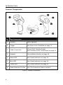
Scanner Components
No. Item Description
1 Window Laser Aperture
2 Trigger See How to use CodeGate on page 17
3 Cable Connection
10-pin RJ45, Female Socket,
See Scanner Pinout Connections on page 32
4 Speaker See Audible Indicators on page 18
5 White LED See Visual Indicators on page 19
6 Blue LED See Visual Indicators on page 19
7 Yellow LED See Visual Indicators on page 19
8 Cable Release Pin-Hole See The PowerLink Cable on page 5
Figure 1. Scanner Components

5
INTRODUCTION
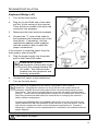
Cable Installation and Removal
Installation
Important: If the cable is not fully latched, the unit can power intermittently.
Figure 2. Connecting the Cable
1. Plug the 10-pin RJ45 end of the cable into the 10-pin socket on the scanner.
There will be an audible click when the connector lock engages.
2. Gently pull on the cable strain relief to insure the cable is securely installed.
Removal
Before removing the cable from the scanner, Metrologic recommends that power
to the host system be turned off. If the cable is a PowerLink cable, disconnect
the power supply on the cable.
Figure 3. Releasing the Cable
1. Locate the small dimple on the handle of the unit near the cable connection.
2. Bend an ordinary paperclip into the shape shown above in Figure 3.
3. To release the cable lock, push the end of the paperclip through the rubber
on the handle where the dimple is located.
4. There will be an audible click when the connector lock releases. Pull gently
on the strain-relief of the cable to separate the cable from the scanner.

6
INTRODUCTION
Labels
Every MS9590 and MS9591 has a serial number label located on the underside
of the scanner head and molded text on the scanner handle. The label and
molded text provide important information such as the unit’s date of manufacture,
serial number, CE and caution information. See Figure 4 for examples of these
items and their location on the scanner.
Figure 4 . Molded Text and Serial Number Label
Caution:
To maintain compliance with applicable standards, all circuits connected to the scanner
must meet the requirements for SELV (Safety Extra Low Voltage) according to EN/IEC
60950-1.
To maintain compliance with standard CSA-C22.2 No. 60950-1/UL 60950-1 and norm
EN/IEC 60950-1, the power source should meet applicable performance requirements for
a limited power source.

7
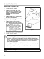
SCANNER INSTALLATION
RS232 (-14)
1. Turn off the host device.
2. Plug the 10-pin RJ45 end of the
PowerLink cable into the 10-pin
socket on the scanner. There will be
an audible click when the connector
lock engages.
3. Connect the 9-pin D-type connector
of the PowerLink cable to the proper
COM port on the host device.
If the scanner is receiving power from the
host system, skip to step #6.
4. Plug the power supply into the power
jack on the PowerLink cable.
Check the AC in input
requirements of the power
supply to verify the voltage
matches the AC outlet.
The outlet must be located
near the equipment and be
easily accessible.
5. Connect AC power to the transformer.
6. Turn on the host device.
The scanner is shipped from the factory configured to set of default
conditions. Plugging the scanner into a port on the host system does
not guarantee that the scanned information will be communicated
properly to the host device. The scanner and host device must use the
same communication protocol. Please refer to the MetroSelect Single-
Line Configuration Guide or the help files provided with MetroSet2 for
instructions on changing the scanner’s factory default configuration.
See caution on page 6.
Figure 5.

8
SCANNER INSTALLATION
RS485
(-106)
1. Turn off the host device.
2. Plug the 10-pin RJ45 end of the
MVC cable into the 10-pin socket
on the scanner. There will be an
audible click when the connector
lock engages.
3. Connect the other end
of the MVC
cable to the host device.
4. Turn on the host device.
5. The blue LED on the scanner will
turn on, the white LED will flash, and
the scanner will beep once.
6. Scan the bar code below to activate
the RS485 interface.
³999995
USB is the default communication protocol for an MS9590-106 and the
MS9591-106. If the recall defaults bar code is scanned after the unit
has been configured for RS485, the scanner will revert to the USB
default communication protocol. The bar code above will need to be
rescanned to return the unit to the RS485 communication protocol.
The scanner is shipped from the factory configured to set of default
conditions. Plugging the scanner into a port on the host system does
not guarantee that the scanned information will be communicated
properly to the host device. The scanner and host device must use the
same communication protocol. Please refer to the MetroSelect Single-
Line Configuration Guide or the help files provided with MetroSet2 for
instructions on changing the scanner’s factory default configuration.
See caution on page 6.
Applicable for IBM
®
host applications
The type of host connection available on an MVC cable is application dependent.
Contact a customer service representative at 1-800-ID-METRO for additional information
on the MVC converter cable series.
Figure 6.

9
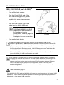
SCANNER INSTALLATION
Keyboard Wedge (-47)
1. Turn off the host device.
2. Plug the 10-pin RJ45 end of the cable
into the 10-pin socket on the scanner.
There will be an audible click when the
connector lock engages.
3. Disconnect the host device's keyboard.
4. Connect the "Y" ends of the cable to
the keyboard and keyboard port on the
host device. If necessary, use the
male/female adapter cable supplied
with the scanner cable to make the
proper connections.
If the scanner is receiving power from the
host system, skip to step #7.
5. Plug the power supply into the power
jack on the PowerLink cable.
Check the AC in input
requirements of the power supply
to verify the voltage matches the
AC outlet. The outlet must be
located near the equipment and
be easily accessible.
6. Connect AC power to the transformer.
7. Turn on the host device.
The scanner is shipped from the factory configured to set of default
conditions. Plugging the scanner into a port on the host system does not
guarantee that the scanned information will be communicated properly to the
host device. The scanner and host device must use the same communication
protocol. Please refer to the MetroSelect Single-Line Configuration Guide or the
help files provided with MetroSet2 for instructions on changing the scanner’s
factory default configuration.
Powering the MS9590-47 or the MS9591-47 directly from the host device may
cause interference with the operation of the scanner or the host device. Not all
host devices supply the same current through the keyboard port. Contact a
Metrologic, customer service representative for information on available external
power supplies.
See caution on page 6.
Figure 7.

10
SCANNER INSTALLATION
Stand-Alone Keyboard (-47)
1. Turn off the host system.
2. Plug the 10-pin RJ45 end of the
cable into the 10-pin socket on the
scanner. There will be an audible
click when the connector lock
engages.
3. Plug the other end of the cable into
the host's keyboard port
If the scanner is receiving power from the
host system, skip to step #6.
4. Plug the power supply into the
power jack on the PowerLink cable.
Check the AC in input
requirements of the power
supply to verify the voltage
matches the AC outlet.
The outlet must be located
near the equipment and be
easily accessible.
5. Connect AC power to the transformer.
6. Turn on the host device.
The scanner is shipped from the factory configured to set of default
conditions. Plugging the scanner into a port on the host system does not
guarantee that the scanned information will be communicated properly to the
host device. The scanner and host device must use the same communication
protocol. Please refer to the MetroSelect Single-Line Configuration Guide or the
help files provided with MetroSet2 for instructions on changing the scanner’s
factory default configuration.
Powering the MS9590-47 or the MS9591-47 directly from the host device may
cause interference with the operation of the scanner or the host device. Not all
host devices supply the same current through the keyboard port. Contact a
Metrologic, customer service representative for information on available external
power supplies.
See caution on page 6.
Figure 8.

11
Figure 9.
SCANNER INSTALLATION
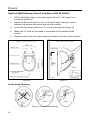
USB (-106,-38-EAS, and -40-EAS)
1. Turn off the host system.
2. Plug the 10-pin RJ45 end of the
USB cable into the 10-pin socket
on the scanner. There will be an
audible click when the connector
lock engages.
3. Plug the USB Type A end of the
cable into the host's USB port.
Cables supplied with MS9590-
38-EAS and MS9590-40-EAS
models have additional wires
for Checkpoint device
connections. Refer to page 12
for additional information on
Checkpoint device connection.
4. Turn on the host device.
USB is the default communication protocol for the MS9590-106 and the
MS9591-106. Both the -38 interface and the -106 interface scanners have USB
Keyboard Emulation Mode enabled by default when shipped from the factory.
Both the -38 interface and the -106 interface scanners are configurable for
Bi-Directional Serial Emulation mode. IBM OEM support is only available with
the MS9590-106 and the MS9591-106.
Refer to the USB section in the MetroSelect Single-Line Configuration Guide
(MLPN 00-02544) for USB configuration bar codes.
The scanner is shipped from the factory configured to set of default conditions.
Plugging the scanner into a port on the host system does not guarantee that the
scanned information will be communicated properly to the host device. The
scanner and host device must use the same communication protocol. Please
refer to the MetroSelect Single-Line Configuration Guide or the help files
provided with MetroSet2 for instructions on changing the scanner’s factory
default configuration.
See caution on page 6.
The MS9590-38-EAS and the MS9590-106 meet the requirements for Full Speed USB
hardware. These interfaces also support all emulation types previously supported by
Metrologic in Low Speed USB scanners.

12
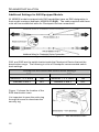
SCANNER INSTALLATION
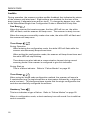
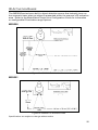
Additional Settings for EAS Equipped Models
All MS9590 models equipped with EAS capabilities have an EAS designation in
their model numbers (example: MS9590-38-EAS). The cable supplied with these
units will have additional wires for Checkpoint Device connections.
Figure 10. EAS Cable Samples
SW1 and SW2 are the switch banks inside the Checkpoint Device that set the
deactivation range. The following is a list of Checkpoint recommended switch
bank settings.
Checkpoint Recommended Switch Bank Settings
SW1 SW2
Switches 1, 4, 5, and 6 ON Switches 1, 4, 5, and 6 ON
Switches 2 and 3 OFF Switches 2 and 3 OFF
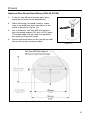
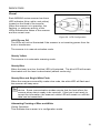
Figure 11 shows the location of the
EAS deactivation area.
It is important to pass the entire tag
through this area to deactivate the
security tag.
Figure 11. EAS Deactivation Area

13
STANDS
Flex Stand Components (PN 46-00709)
Item Item Description Qty.
A Cradle Coupler 1
B Cradle 1
C Flexible Shaft 1
D Screw Cap 2
E Stand Base 1
F ¼" - 20 x ⅜" Flat Head Phillips Screw, 100° Undercut 2
G #8 Round Head Wood Screw 2
H M3 -.5 x 20 mm, Pan Head Phillips Screw 1
J M3 Flat Washer 1
K M3 Split Lock Washer 1
L Flexible Shaft Cover 1
Figure 12. Stand Components

14
STANDS
Flex Stand Assembly (PN 46-00709)
Figure 13. Stand Assembly

15
Figure 14.
STANDS
Optional Flex Stand Fixed Mount (PN 46-00709)
1. In the kit, two #8 wood screws have been
provided for fixed mount applications.
2. When choosing the stand location, make
sure to consider the front orientation of the
stand (indicated in Figure 14).
3. On a centerline, drill two #39 pilot holes in
the countertop spaced 125 mm (4.92") apart.
The stand base can be used as a guide for
the spacing of the pilot holes.
4. Secure the stand base to the countertop with
the two #8 wood screws provided.
Figure 15. Stand Base Hole Pattern (Not to Scale)

16
STANDS
Optional Wall/Tabletop Stand Fixed Mount (PN 46-00885)
1. Drill two #39 pilot holes in the wall spaced 39 mm (1.54") apart on a
horizontal centerline.
2. Install one #8 wood screw in each of the pilot holes, leaving a space
between the head of the screw and the wall surface.
3. Locate the two slots marked as "A" on the stand base in Figure 16.
4. Match the "A" slots on the stand to the heads of the installed wood
screws.
5. Slide the stand over the screw heads and down to lock the stand in place.
Figure 16. Figure 17
Cradle Angle Warning
Figure 18. Cradle Angle Warning
Page is loading ...
Page is loading ...
Page is loading ...
Page is loading ...
Page is loading ...
Page is loading ...
Page is loading ...
Page is loading ...
Page is loading ...
Page is loading ...
Page is loading ...
Page is loading ...
Page is loading ...
Page is loading ...
Page is loading ...
Page is loading ...
Page is loading ...
Page is loading ...
Page is loading ...
Page is loading ...
Page is loading ...
Page is loading ...
Page is loading ...
Page is loading ...
Page is loading ...
Page is loading ...
Page is loading ...
-
 1
1
-
 2
2
-
 3
3
-
 4
4
-
 5
5
-
 6
6
-
 7
7
-
 8
8
-
 9
9
-
 10
10
-
 11
11
-
 12
12
-
 13
13
-
 14
14
-
 15
15
-
 16
16
-
 17
17
-
 18
18
-
 19
19
-
 20
20
-
 21
21
-
 22
22
-
 23
23
-
 24
24
-
 25
25
-
 26
26
-
 27
27
-
 28
28
-
 29
29
-
 30
30
-
 31
31
-
 32
32
-
 33
33
-
 34
34
-
 35
35
-
 36
36
-
 37
37
-
 38
38
-
 39
39
-
 40
40
-
 41
41
-
 42
42
-
 43
43
-
 44
44
-
 45
45
-
 46
46
-
 47
47


Honeywell MS9590 VoyagerGS User guide
- Category
- Bar code readers
- Type
- User guide
Ask a question and I''ll find the answer in the document
Finding information in a document is now easier with AI
Related papers
-
Metrologic VoyagerGS 9590 Series User manual
-
Honeywell 46-00709 Datasheet
-
Metrologic Orbit MS7120-38 User manual
-
Honeywell MS7120 User manual
-
-
Honeywell AP-010-BT User manual
-
Metrologic Orbit MS7120 User guide
-
Metrologic MS3780 User manual
-
-
Metrologic IS3480 QuantumE User manual
Other documents
-
Metrologic Instruments MS9590i User manual
-
-
-
-
-
SBS CO9P30550 Datasheet
-
HandStands XV-G2 User guide
-
-
Metrologic MS1691 – 106 User manual
-
BTC 9116 User manual