Modern Forms FR-W1916-56L-GW Installation guide
- Category
- Household fans
- Type
- Installation guide
This manual is also suitable for

INSTALLATION INSTRUCTIONS
NIRVANA 56”
FR-W1916-56L
DC
MOTOR
WET
SMART
works with the
Google Assistant
modernforms.com

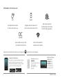
2 FR-W1916-56L
RF Wall Control
F-WC-WT
Included with each fan
6 Fan speeds
Dims light to 1%
ON/OFF
WIFI Touch Panel
Wall Control
F-TS-BK Black
F-TS-WT White
Sold separately
Full app control
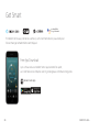
FREE APP DOWNLOAD
Sync with our exclusive Modern Forms
app to control fan speed, use smart
features like Adaptive Learning, create
groups and reduce energy costs
App Instructions And Smart Home Device Integration modernforms.com/mfappins
Durably nished and rated
for indoor and outdoor use
WET
Wet location-listed and
manufactured to the strictest
ETL/cETL safety regulations
Integrates with smart devices for
remote and voice activated control
Quiet, reliable, and up to 70%
more ecient than AC fans
Wi-Fi and RF enabled for
unlimited control options
DC
MOTOR
SMART
All Modern Forms fans are:

3FR-W1916-56L
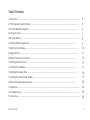
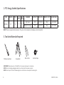
1 Safety Rules..................................................................................................................................................................................
2 FTC Energy Guide & Specications........................................................................................................................................
3 Tools And Materials Required..............................................................................................................................................
4 Package Contents......................................................................................................................................................................
5 Mounting Options.....................................................................................................................................................................
6 Installing the Mounting Bracket.....................................................................................................................................
7 Attaching the Fan Blades.......................................................................................................................................................
8 Hanging the Fan.........................................................................................................................................................................
9 Making the Electrical Connections...................................................................................................................................
10 Installing the Wall Control ..............................................................................................................................................
11 Finishing the Installation....................................................................................................................................................
12 Installing the Adapter Plate ..............................................................................................................................................
13 Installing the LED Luminaire Module..............................................................................................................................
14 Wall Control Operating Instructions...........................................................................................................................
15 Application.................................................................................................................................................................................
16 Troubleshooting.....................................................................................................................................................................
17 Accessories................................................................................................................................................................................
4
6
6
7
8
9
10
11
13
15
17
18
19
20
24
26
28
Table Of Contents

4 FR-W1916-56L
For operation, maintenance, and troubleshooting information, visit modernforms.com/help.
1. To reduce the risk of electric shock, ensure electricity has been
turned o at the circuit breaker before beginning.
2. All wiring must be in accordance with the National Electrical
Code “ANSI/NFPA 70” and local electrical codes. Electrical
installation should be performed by a licensed electrician.
3. To reduce the risk of re, electric shock, personal injury or
damage to the fan or other items, the outlet box and support
structure must be securely mounted and capable of reliably
supporting a minimum of 35 Ibs (15.9 kg). Use only UL/cUL
listed outlet boxes marked “FOR FAN SUPPORT.”
Use only the screws and washers provided with the outlet box.
4. The fan must be mounted with a minimum of 7 ft. (2.1m)
clearance from the trailing edge of the fan blades to the oor
and a minimum of 1.5 ft (0.5m) from the edge of the fan blades
to the surrounding walls.
5. Never place objects in the path of the fan blades.
6. To avoid personal injury or damage to the fan and other items,
please be cautious when working around or cleaning the fan.
7. To avoid electrical shock or damage to the motor or nish,
do not use water or chemicals when cleaning the fan or fan
blades. A dry cloth or lightly dampened cloth will be suitable
for most cleaning.
8. After making electrical connections, spliced conductors should
be turned upward and pushed carefully up into the outlet box.
The wires should be spread apart with the grounded
conductor and the equipment-grounding conductor on one
side of the outlet box, and the ungrounded conductor on the
other side of the outlet box.
9. All set screws must be checked and re-tightened where
necessary before installation.
1. Safety Rules

5FR-W1916-56L
WARNING: Do not install or use your fan if any part(s) is/are
damaged or missing. This product is designed for use only with
the supplied parts and/or accessories designated for use with this
product by Modern Forms. Substitution of parts or accessories not
designated for use with this product by Modern Forms could result
in personal injury or property damage and will void the warranty.
Contact an authorized dealer or the manufacturer if any parts are
damaged or missing.
WARNING: To reduce the risk of electric shock, this fan must be
installed and operated with the supplied wall control, or controlled
from the Modern Forms app or Wi-Fi Touch Panel Wall Control
(not included).
WARNING: Do not use power tools to assemble or install your fan.
Using power tools can result in improper assembly which can lead
to noise or fan damage, personal injury or property damage.
WARNING: To reduce the risk of personal injury, do not bend the
blade arms when installing the brackets, balancing the blades or
cleaning the fan.
WARNING: Do not insert foreign objects between rotating fan blades.
WARNING: Do not operate fan unless fan blades are in place.
Noise and fan damage can occur.
WARNING: This appliance is not intended for use by young
children without supervision.
CAUTION: Before assembling your fan, refer to the “Making the
Electrical Connections“ section. If you feel you do not have enough
wiring knowledge or experience, have your fan installed by a
licensed electrican.
NOTE: Before servicing or cleaning the fan, switch power o at the
circuit breaker.

6 FR-W1916-56L
Electrical tape
NOTE: These are approximate measures. They do not include amps and wattage used by the light kit.
FAN FAN SIZE VOLTS N.W
(lbs)
G.W
(lbs)
STANDARD ELECTRICITY AIR FLOW ENERGY COSTS* FAN EFFICACY
NIRVANA 56” 120 17.17 29.45
High Speed 28W 6783 CFM $8/yr 244 CFM/W
Weighted Average 16W 4264 CFM $5/yr 265 CFM/W
Phillips screwdriver Step ladder
Wire cutters
IMPORTANT: Please make note of the MAC ID on the receiver and keep it in a safe place.
NOTE: Before discarding packaging materials, be certain all parts have been removed.
NOTE: Place the parts from the hardware bag into a small container to keep them from being lost.
3. Tools And Materials Required
2. FTC Energy Guide & Specications

7
NOTE: ** denotes nish code of fan
A
G
H
I
L
D
M
J
K
B
E
F
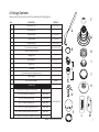
REF. DESCRIPTION PART NO.
A Blade Set of 3 (3B1) RPL-F1916-56-BD-**
B Blade Holder Ring
---
C Hanger Assembly
RPL-HGR-ASM-**
Hanger Bracket
RPL-CAN-RND.**
Downrod Assembly RPL-COU-CVR
D Control Receiver w/Hardware RPL-F1916-56-REC
E Canopy w/ Canopy Screw Ring ---
F Coupling Cover ---
G Motor Assembly F4IN-120V-R1-30
H Adapter Plate ---
I LED Module ---
J Light Shade (Aluminum and glass)(1pc each) ---
K Upper Housing
---
L Wall Control w/Hardware
F-WC-WT
M Hardware Bag
4 x 9mm at Head Customed Philips Screw (7pcs) Blade Holder Ring
RPL-NIRVANA-PARTS
3/16 x 3/8 Flat Head Philip Screw (7pcs) Blade Screws
Ø5 x 14 x 1mm Flat Washer (7pcs) Blade Screws
Ø6.5 x 19 x 2mm Flat Washer (1pc) Safety Cable
3/16” (Ø5.2 x 8.4 x 1.0mm) Spring Washer (1pcs) Safety Cable
#10 x 76mm Pan Head Phillip Wood Screws (1pcs) Safety Cable
5/32” x 1/4mm Phil Truss Head Screw (Water Proof) (4pcs) For LED Module
C
4. Package Contents
Unpack your fan and check the contents. You should have the following items:

8 FR-W1916-56L
CAUTION: To prevent electrical shock, ensure electricity has been
turned o at the circuit breaker before beginning.
If there isn’t an existing UL/cUL listed outlet box, please refer to the
following instructions. Secure the outlet box directly to the building
structure. Use appropriate fasteners and building materials. The
outlet box and support structure must be able to fully support the
moving weight of the fan (at least 35 lbs/15.9 kg). Do not use plastic
outlet boxes. Use only UL/cUL listed outlet boxes marked
“FOR FAN SUPPORT.”
Secure the outlet box directly to the building structure.
Use appropriate fasteners and building materials. The outlet box
and its support must be able to fully support the moving weight
of the fan (at least 35 lbs). Do not use plastic outlet boxes.
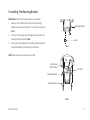
Figures 1-4 are examples of dierent ways to mount the
outlet box.
NOTE: To hang your fan where there is an existing xture but no
ceiling joist, you may need an installation hanger bar.
NOTE: Downrod fans can be suspended up to a maximum
recommended length of 72” using additional downrods
(sold separately) and the included 80” lead wire.
NOTE: The sloped ceiling kit (sold separately) is required for sloped
ceiling applications, and will accommodate slopes up to 45° (FIG.3).
NOTE: You may need a longer downrod to maintain proper blade
clearance when installing on a steep, sloped ceiling (FIG. 3).
FIG. 1
Outlet Box
Outlet Box
Outlet Box
Provides Strong Support
Mounting Bracket
Recessed
Outlet Box
SLOPED CEILING
MAX 30° ANGLE
FIG. 2
FIG. 4
FIG. 3
Joist
Support
Brace
5. Mounting Options

9FR-W1916-56L
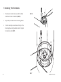
Remember to disconnect the power at the circuit breaker.
1. Remove 1 of 2 screws from the bottom of the mounting
bracket and save for use in section 11. Loosen the other screw
(FIG.5).
2. Pass the 120-volt supply wires through the center hole in the
mounting bracket as shown (FIG.6).
3. Secure the mounting bracket to the ceiling outlet box with the
screws and washers provided with your outlet box.
NOTE: Make sure that mounting screws are tight.
FIG.5
FIG.6
UL/Cul Listed
Electrical Box
Mounting Bracket
Mounting Screws
120V Wire
Mounting Bracket
Screw
6. Installing The Mounting Bracket

10 FR-W1916-56L
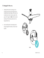
1. Place blade on motor and secure with the blade
attachment screws and washers (FIG.7A).
2. Repeat this procedure with the remaining blades .
3. Turn fan assembly over and secure the top of the
blades together using the blade collector ring and
hardware provided (FIG.7).
FIG.7
FIG.7A
7. Attaching The Fan Blades

11FR-W1916-56L
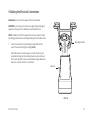
Assemble upper housing to motor assembly using the
6 screws provided (FIG. 8).
1. Take out the screw located in the hanger ball, lower the hanger
ball and remove the cross pin. Remove the hanger ball from
the hanger ball/downrod assembly.
2. Remove the clevis pin and cotter pin and loosen the two collar
screws from the motor collar.
3. Feed motor wires and safety cable through coupling cover,
canopy ring, and canopy.
4. Carefully feed the motor wires and safety cable up through the
downrod. Thread the downrod assembly onto motor collar.
5. Align the holes of the downrod and collar and insert the cotter
pin and clevis pin. Tighten the two collar screws.
6. Slip the coupling cover, canopy screw ring (painted side down),
and canopy (opened side up) onto the downrod.
7. Reinstall the hanger ball onto the downrod, being sure that the
cross pin is in the correct position and the screw is tightened.
WARNING: Failure to properly install the cotter pin and/or tighten
the set screws could result in the fan loosening and possibly falling.
Take special care to make sure the cotter pin is reattached.
NOTE: Make sure all screws are tightened and that wires are not
twisted.
8. Hanging The Fan
FIG.8

12 FR-W1916-56L
1. Carefully lift the fan motor assembly up to the
mounting bracket and seat the hanger ball in the
mounting bracket socket. Make sure the tab on the
mounting bracket socket is properly seated in the
groove in the hanger ball (FIG.9). Rotate the socket
assembly until the ball drops and locks into the
hanger bracket screw.
2. Secure the safety cable to the building structure
using spring washer, at washer, and wood screw
provided.
FIG. 9
8. Hanging the fan (cont.)

13FR-W1916-56L
Mounting Bracket
Receiver
Remember to disconnect the power at the circuit breaker.
CAUTION: If you feel you do not have enough wiring knowledge or
experience, have your fan installed by a licensed electrician.
NOTE: Installation of this fan requires that a three-conductor cable
(including ground wire) be run between ceiling and wall outlet boxes.
1. Insert the receiver into the mounting bracket with the at
side of the receiver facing the ceiling (FIG.10).
Follow the steps on the next page to connect the fan to your
household wiring. Use the included plastic wire nuts with your
fan. Secure the plastic wire nuts with electrical tape. Make sure
there are no loose strands or connections.
FIG.12
FIG.6
FIG. 10
9. Making the Electrical Connections

14 FR-W1916-56L
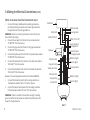
FIG. 11
White (neutral)
Outlet Box
Black (hot)
Black (“AC IN L”)
Red (to motor)
Gray (to motor)
Yellow (to motor)
Yellow (motor)
Gray (motor)
Red (motor)
Receiver
Green (Ground)
To hanger ball
Green (Ground)
To hanger bracket
Green (Ground)
White (for light)
White (for light)
Blue (for light)
Blue (for light)
White (“AC IN N”)
Green (ground)
Motor to receiver electrical connections: (FIG.11)
1. Connect the hanger ball/downrod assembly ground wire,
mounting bracket ground wire and receiver ground wire to
the ground wire in the ceiling outlet box.
WARNING: Failure to connect ground wires could result in poor
fan control functionality.
2. Connect the red wire from the fan to the red wire marked
“TO MOTOR” from the receiver.
3. Connect the gray wire from the fan to the gray wire marked
“TO MOTOR” from the receiver.
4. Connect the yellow wire from the fan to the yellow wire marked
“TO MOTOR” from the receiver.
5. Connect the white wire from the fan to the white wire marked
‘FOR LIGHT” from the receiver.
6. Connect the black wire from the fan to the black wire marked
“FOR LIGHT” from the receiver.
Receiver to house supply wires electrical connections (FIG.11):
1. Connect the black (hot) wire from the ceiling outlet box to
the black wire marked “AC in L” from the receiver.
2. Connect the white (neutral) wire from the ceiling outlet box
to the white wire marked “AC in N” from the receiver.
WARNING: Check to see that all connections are tight, including
ground, and that no bare wires are visible at the plastic wire nuts
except for the ground wire.
9. Making the Electrical Connections (cont.)

15FR-W1916-56L
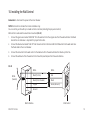
FIG.12
White White
Red
Black
Green (Ground)
Black (To Fan)
Copper
Ground
Black (From Breaker)
Wall ControlWall Outlet Box
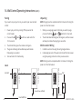
Remember to disconnect the power at the circuit breaker.
NOTE: Wall control is intended for indoor installation only.
You can control your fan with up to 4 wall controls or remotes (including the pre-paired control).
Wall control to wall outlet box electrical connections (FIG.12):
1. Connect the green wire marked “GROUND” from the wall control to the copper wire from the wall outlet box that feeds
back to the circuit breaker – important for proper fan function.
2. Connect the black wire marked “LINE IN” from the wall control to the black LINE VOLTAGE wire from the wall outlet box
that feeds back to the circuit breaker.
3. Connect the red wire from the wall control to the black wire from the wall outlet box that feeds up to the fan.
4. Connect the white wire from the wall control to the white (neutral) wire from the wall outlet box.
10. Installing the Wall Control
White
(Neutral)

16 FR-W1916-56L
FIG.13
10. Installing the Wall Control (cont.)
Remember to disconnect the power at the circuit breaker.
1. Carefully tuck the wire connections inside the outlet box.
Secure the wall control with the 2 wall control screws
provided (FIG.13).
2. Attach the wall mounting plate over the wall control and
secure with the 2 wall mounting plate screws provided.
3. Fasten the wall plate to the wall mounting plate.
NOTE: Fan(s) are required to be installed within 30 feet of the
wall control to ensure reliable communication.
NOTE: A maximum of 2 fans can operate on a circuit through
the wall control.
NOTE: A maximum of 12 fans can operation through an on/o
switch or breaker when utilizing the Modern Forms app for
the fan control (without the wall control in the circuit).
Wall Mounting Plate
Wall Outlet Box
Wall Control
Wall PlateMounting Screws

17FR-W1916-56L
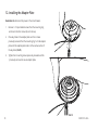
1. Secure all wire connections with supplied wire ties to assist
in canopy installation.
2. Tuck connections neatly into ceiling outlet box.
3. Slide the canopy up to mounting bracket and place the key
hole on the canopy over the screw on the mounting bracket.
Turn canopy until it locks in place at the narrow section of
the key holes (FIG.14).
4. Align the circular hole on canopy with the remaining hole
on the mounting bracket. Secure by tightening the one screw
previously loosened and the one previously removed.
5. Adjust the canopy screws as necessary until the canopy and
canopy screw ring are snug.
WARNING: Make sure tab at bottom of hanger bracket is properly
seated in groove of hanger ball before attaching canopy to bracket.
Failure to properly seat tab in groove could cause damage to
electrical wiring.
FIG.14
11. Finishing the Installation

18 FR-W1916-56L
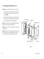
Remember to disconnect the power at the circuit breaker.
1. Remove 1 of 3 pre-installed screws from the mounting ring
and loosen the other screws (do not remove).
2. Place key holes in the adapter plate over the 2 screws
previously loosened from the mounting ring. Turn the adapter
plate until the adapter plate locks in at the narrow section of
the key holes (FIG.15).
3. Tighten the 2 mounting screws previously loosened and the
1 previously removed to secure adapter plate.
FIG.15
12. Installing the Adapter Plate

19FR-W1916-56L
FIG.16
FIG.17
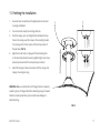
WARNING: Before starting installation, disconnect the power by
turning o the circuit breaker or removing the fuse at the fuse box.
Turning power o using the fan switch is not sucient to prevent
electrical shock.
CAUTION: To reduce the risk of electric shock, disconnect the
electrical supple circuit to the fan before installing light kit.
NOTE: If you do not plan to install the luminaire module with your
fan at this time, skip to step 4.
1. Securely attach the LED wires to the wires coming from the
motor. Male to male and female to female (FIG.16).
2. Secure the LED module with the 3 screws to the mounting
plate (FIG.17).
3. Install glass shade by turing it clockwise until it locks securely
(FIG.17).
4. If installing the optional metal light cover, make sure it is
securely tightened.
13. Installing the LED Luminaire Module (optional)
S
Glass Light shade

20 FR-W1916-56L
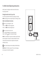
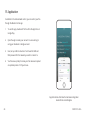
Restore power to ceiling fan and test wall control as below
for proper operation.
Pairing the wall control to your fan
Your fan is pre-paired at the factory. No pairing is necessary.
NOTE: For pairing instructions please skip to the “Pairing” section.
Wall Control Button Functions
button: Turns the light ON or OFF.
Press or hold to increase the light level.
Press or hold to decrease the light level.
button: Turns the fan ON or OFF.
Press or hold the button to increase fan speed.
Press or hold the button to decrease fan speed.
NOTE: Your fan features 6 speeds. An audible tone will indicate
when the speed is increased or decreased. When the fan has
reached the minimum/maximum speed level the audible
indication will stop.
button: Switch between Summer Mode and Winter Mode.
ON-OFF Switch: Pull tab to power o in case of emergency.
Not necessary for normal fan operation.
ON-OFF SWITCH
14. Wall Control Operating Instructions
Page is loading ...
Page is loading ...
Page is loading ...
Page is loading ...
Page is loading ...
Page is loading ...
Page is loading ...
Page is loading ...
Page is loading ...
Page is loading ...
Page is loading ...
Page is loading ...
-
 1
1
-
 2
2
-
 3
3
-
 4
4
-
 5
5
-
 6
6
-
 7
7
-
 8
8
-
 9
9
-
 10
10
-
 11
11
-
 12
12
-
 13
13
-
 14
14
-
 15
15
-
 16
16
-
 17
17
-
 18
18
-
 19
19
-
 20
20
-
 21
21
-
 22
22
-
 23
23
-
 24
24
-
 25
25
-
 26
26
-
 27
27
-
 28
28
-
 29
29
-
 30
30
-
 31
31
-
 32
32


Modern Forms FR-W1916-56L-GW Installation guide
- Category
- Household fans
- Type
- Installation guide
- This manual is also suitable for
Ask a question and I''ll find the answer in the document
Finding information in a document is now easier with AI
Related papers
-
Modern Forms FR-W1815 Windflower 60 Installation guide
-
-
-
-
-
-
-
-
-
Other documents
-
Home Decorators Collection SW1791 MBK Operating instructions
-
AireRyder FN433 series Instructions For Installation And Use Manual
-
-
 Designers Choice Collection AC18842-SN Operating instructions
-
 Kichler Lighting 370036ALMTR User manual
-
 Designers Choice Collection AC19052-PL Installation guide
-
 Craftmade COUPLER-BN Installation guide
-
 Designers Choice Collection AC17152-SN Installation guide
-
OUKANING HG-WMTZXL-2624 Operating instructions
-
Kichler Lighting 330174MWH User manual


