Page is loading ...

Portable Generator Owner’s Manual
Questions? Help is just a moment away!
Call: Generac Generator Helpline - 1-800-270-1408 M-F 8-5 CT
Web: www.generac-portables.com or www.briggsandstratton.com
Model No. 1647-0 (8,000 Watt AC Generator) Manual No. 189065GS Revision 4 (08/08/2003)
2
PowerBoss 8,000 Watt PowerMaster Generator
TABLE OF CONTENTS
Safety Rules. . . . . . . . . . . . . . . . . . . . . . . . . . . . . . . . . . 2-4
Know Your Generator . . . . . . . . . . . . . . . . . . . . . . . . . . . 5
Assembly. . . . . . . . . . . . . . . . . . . . . . . . . . . . . . . . . . . . 6-7
Operation . . . . . . . . . . . . . . . . . . . . . . . . . . . . . . . . . . 8-11
Maintenance . . . . . . . . . . . . . . . . . . . . . . . . . . . . . . . . . . 12
Storage. . . . . . . . . . . . . . . . . . . . . . . . . . . . . . . . . . . . . . 13
Troubleshooting . . . . . . . . . . . . . . . . . . . . . . . . . . . . . . . 14
Notes. . . . . . . . . . . . . . . . . . . . . . . . . . . . . . . . . . . . . . . 15
Schematic/Wiring Diagram . . . . . . . . . . . . . . . . . . . . 16-17
Replacement Parts. . . . . . . . . . . . . . . . . . . . . . . . . . . 18-22
Warranty . . . . . . . . . . . . . . . . . . . . . . . . . . . . . . . . . . . . 23
EQUIPMENT
DESCRIPTION
Read this manual carefully and become familiar
with your generator. Know its applications, its
limitations and any hazards involved.
This generator is an engine–driven, revolving field,
alternating current (AC) generator. It was designed to
supply electrical power for operating compatible electrical
lighting, appliances, tools and motor loads.The generator’s
revolving field is driven at about 3,600 rpm by the engine.
CAUTION! DO NOT exceed the generator’s
wattage/amperage capacity. See “Don’t Overload
Generator” on page 11.
Every effort has been made to ensure that information in
this manual is accurate and current. However, we reserve
the right to change, alter or otherwise improve the product
and this document at any time without prior notice.
The Emission Control System for this generator is
warranted for standards set by the Environmental
Protection Agency. For warranty information refer to the
engine owner’s manual.
SAFETY RULES
This is the safety alert symbol. It is used to
alert you to potential personal injury hazards.
Obey all safety messages that follow this
symbol to avoid possible injury or death.
The safety alert symbol ( ) is used with a signal word
(DANGER, CAUTION,WARNING), a pictorial and/or a
safety message to alert you to hazards. DANGER indicates
a hazard which, if not avoided, will result in death or
serious injury. WARNING indicates a hazard which, if not
avoided, could result in death or serious injury.
CAUTION indicates a hazard which, if not avoided, might
result in minor or moderate injury. CAUTION, when used
without the alert symbol, indicates a situation that could
result in equipment damage. Follow safety messages to
avoid or reduce the risk of injury or death.
Hazard Symbols and Meanings
The engine exhaust from this product contains
chemicals known to the State of California to cause
cancer, birth defects, or other reproductive harm.
WARNING
In the State of California a spark arrester is required by law
(Section 4442 of the California Public Resources Code).
Other states may have similar laws. Federal laws apply on
federal lands. If you equip the muffler with a spark arrester,
it must be maintained in effective working order.
Fire
Explosion
Toxic Fumes
Hot Surface
Electrical Shock
Electrocution
Electrical Shock
Explosive Pressure
Chemical Burn
3
PowerBoss 8,000 Watt PowerMaster Generator
• Operate generator ONLY outdoors.
• Keep at least 2 feet of clearance on all sides of generator for
adequate ventilation.
• DO NOT operate generator inside any building or enclosure,
including the generator compartment of a recreational vehicle (RV).
Running generator gives off carbon monoxide,
an odorless, colorless, poison gas.
Breathing carbon monoxide will cause nausea,
fainting or death.
DANGER
WHEN ADDING FUEL
• Turn generator OFF and let it cool at least 2 minutes before
removing gas cap. Loosen cap slowly to relieve pressure in tank.
• Fill fuel tank outdoors.
• DO NOT overfill tank.Allow space for fuel expansion.
• Keep fuel away from sparks, open flames, pilot lights, heat, and
other ignition sources.
• DO NOT light a cigarette or smoke.
WHEN OPERATING EQUIPMENT
• DO NOT tip engine or equipment at angle which causes fuel
to spill.
• This generator is not for use in mobile equipment or marine
applications.
WHEN TRANSPORTING OR REPAIRING EQUIPMENT
• Transport/repair with fuel tank EMPTY or with fuel shutoff
valve OFF.
• Disconnect spark plug wire.
WHEN STORING FUEL OR EQUIPMENT WITH FUEL
IN TANK
• Store away from furnaces, stoves, water heaters, clothes
dryers or other appliances that have pilot light or other
ignition source because they can ignite fuel vapors.
Fuel and its vapors are extremely flammable and
explosive.
Fire or explosion can cause severe burns or
death.
WARNING
• DO NOT allow any open flame, spark, heat, or lit cigarette
during and for several minutes after charging a battery.
• Wear protective goggles, rubber apron, and rubber gloves.
Storage batteries give off explosive hydrogen gas
during recharging.
Hydrogen gas stays near battery for a long time
after battery has been charged.
Slightest spark will ignite hydrogen and cause
explosion.
You can be blinded or severely injured.
Battery electrolyte fluid contains acid and is
extremely caustic.
Contact with battery fluid will cause severe
chemical burns.
DANGER
• When using generator for backup power, notify utility
company. Use approved transfer equipment to isolate
generator from electric utility.
• Use a ground fault circuit interrupter (GFCI) in any damp or
highly conductive area, such as metal decking or steel work.
• DO NOT touch bare wires or receptacles.
• DO NOT use generator with electrical cords which are worn,
frayed, bare or otherwise damaged.
• DO NOT operate generator in the rain.
• DO NOT handle generator or electrical cords while standing
in water, while barefoot, or while hands or feet are wet.
• DO NOT allow unqualified persons or children to operate or
service generator.
Generator produces powerful voltage.
Failure to isolate generator from power utility
can result in death or injury to electric utility
workers due to backfeed of electrical energy.
DANGER
• This generator does not meet U. S. Coast Guard Regulation
33CFR-183 and should not be used on marine applications.
• Failure to use the appropriate U. S. Coast Guard approved
generator could result in bodily injury and/or property
damage.
WARNING
4
PowerBoss 8,000 Watt PowerMaster Generator
• DO NOT touch hot surfaces.
• Allow equipment to cool before touching.
Running engines produce heat.Temperature of
muffler and nearby areas can reach or exceed
150°F (65°C).
Severe burns can occur on contact.
WARNING
• DO NOT tamper with governed speed. Generator supplies
correct rated frequency and voltage when running at governed
speed.
• DO NOT modify generator in any way.
Excessively high operating speeds increase risk of injury
and damage to generator.
Excessively low speeds impose a heavy load.
CAUTION
• See “Don’t Overload Generator” on page 11.
• Start generator and let engine stabilize before connecting
electrical loads.
• Connect electrical loads in OFF position, then turn ON for
operation.
• Turn electrical loads OFF and disconnect from generator
before stopping generator.
Exceeding generators wattage/amperage capacity can
damage generator and/or electrical devices connected
to it.
CAUTION
• Use generator only for intended uses.
• If you have questions about intended use, ask dealer or call
1-800-270-1408.
• Operate generator only on level surfaces.
• DO NOT expose generator to excessive moisture, dust, dirt,
or corrosive vapors.
• DO NOT insert any objects through cooling slots.
• If connected devices overheat, turn them off and disconnect
them from generator.
• Shut off generator if:
-electrical output is lost;
-equipment sparks, smokes, or emits flames;
-unit vibrates excessively.
Improper treatment of generator can damage it and
shorten its life.
CAUTION
WHEN ADJUSTING OR MAKING REPAIRS TO YOUR
GENERATOR
• Disconnect the spark plug wire from the spark plug and place
the wire where it cannot contact spark plug.
Unintentional sparking can result in fire or
electric shock.
WARNING

5
PowerBoss 8,000 Watt PowerMaster Generator
120 Volt AC, 20 Amp, Duplex Receptacle — May be
used to supply electrical power for the operation of
120 Volt AC, 20 Amp, single phase, 60 Hz electrical lighting,
appliance, tool and motor loads.
120 Volt AC, 30 Amp Locking Receptacle — May be
used to supply electrical power for the operation of
120 Volt AC, 30 Amp, single phase, 60 Hz electrical lighting,
appliance, tool and motor loads.
120/240 Volt AC, 30 Amp Locking Receptacle — May
be used to supply electrical power for the operation of
120 and/or 240 Volt AC, 30 Amp, single phase, 60 Hz
electrical lighting, appliance, tool and motor loads.
120/240 Volt AC, 50 Amp Receptacle — May be used
to supply electrical power for the operation of 120/240 Volt
AC, 50 Amp, single phase, 60 Hz electrical loads.
Air Cleaner — Uses a dry type filter element and foam
pre–cleaner to limit the amount of dirt and dust sucked
into the engine.
Choke Lever — Used when starting a cold engine.
Circuit Breakers (AC) — Each receptacle is provided
with a "push to reset" circuit breaker to protect the
generator against electrical overload.
Fuel Tank — Capacity of seven (7) U.S. gallons.
Grounding Fastener — If required, please consult a
qualified electrician, electrical inspector, or the local agency
having jurisdiction.
On/Off Switch — Set this switch to “On” before starting
unit. Set switch to “Off” to shut down the engine.
Recoil starter — Used to start the engine.
Spark Arrester Muffler — Exhaust muffler lowers
engine noise and is equipped with a spark arrester screen.
KNOW YOUR GENERATOR
Read this owner’s manual and safety rules before operating your generator.
Compare the illustrations with your generator, to familiarize yourself with the locations of various controls and
adjustments. Save this manual for future reference.
120 Volt AC, 20 Amp
Duplex Receptacle
120/240 Volt AC,
50 Amp Receptacle
Fuel Tank
Choke Lever
Recoil Starter
On/Off Switch
120 Volt AC, 30 Amp
Receptacle
Circuit Breakers (AC)
120/240 Volt AC,
30 Amp Receptacle
Spark Arrester Muffler
Air Cleaner
Grounding Fastener

6
PowerBoss 8,000 Watt PowerMaster Generator
ASSEMBLY
Your generator requires some assembly and is ready for
use after it has been properly serviced with the
recommended oil and fuel.
If you have any problems with the assembly of your
generator, please call the generator helpline at
1-800-270-1408.
Remove Generator From Carton
• Set the palleted carton on a rigid flat surface.
• Carefully cut bands around the shipping carton.
• Lift carton off the generator.
• Remove all packing material, carton fillers, etc.
• Remove the generator from the shipping pallet.
Carton Contents
Check all contents. If any parts are missing or damaged, call
the generator helpline at 1-800-270-1408.
• The generator
• Electric start battery cables
• Generator and engine owner’s manuals
• Locking 30 Amp plugs
• Battery mounting bracket/hardware
• 2 bottles engine oil
• Wheel kit
INSTALL WHEEL KIT
NOTE: Wheel kit is not intended for over-the-road use.
To install your wheel kit, you need the following tool:
• Socket wrench with 1/2" or 13mm sockets.
• Neddle-nose pliers
Install Wheel Kit as follows: (See Figure 1)
1. Place generator on a hard flat surface.
2. Stand at control panel end of generator and gently tilt
generator up, high enough to place wooden blocks
beneath cradle.This will allow you to add wheels.
3. Slide axle through holes in brackets provided on
generator cradle.
4. Slide a wheel spacer, wheel and flat washer on one end
of axle. Make sure air inflation valve is outward. Place
e-ring onto groove in axle.
5. Place one end of needle nose pliers on bottom of axle
and other end of pliers on top of e-ring. Seat e-ring by
pressing pliers closed.
6. Slide axle through until wheel is tight against bracket.
7. Install e-ring on other side in same manner as steps 4
& 5. Remove wooden blocks.
8. Attach vibration mounts to support leg with a 30mm
capscrew and lock nut.
E-Ring
Wheels
Axle
20mm
Capscrew
30mm
Capscrew
Flatwasher
Vibration
Mount
Support Leg
Locknut
Figure 1 — Assemble Wheel Kit
FlatwasherFlatwasher
Lockwasher
7
PowerBoss 8,000 Watt PowerMaster Generator
9. With wheels on, secure support leg assembly to cradle
with 20 mm long capscrews, flat washers, and lock
washers.
10. Check each fastener to ensure it is secure and tires
are inflated between 15-40 PSI.
INSTALLING BATTERY
NOTE: The generator can be started manually. If you
choose not to use the electric start feature of this
generator, you do not need to install the battery.
CAUTION! If battery is not installed, DO NOT
operate engine without insulating the red positive
battery cable with electrical tape, or it could blow a
fuse and cause sparks.
We recommend you purchase and install a Briggs &
Stratton 12 Volt DC battery (Group U1;Type GT-X).The
battery should be serviced with electrolyte fluid and fully
charged prior to installation.
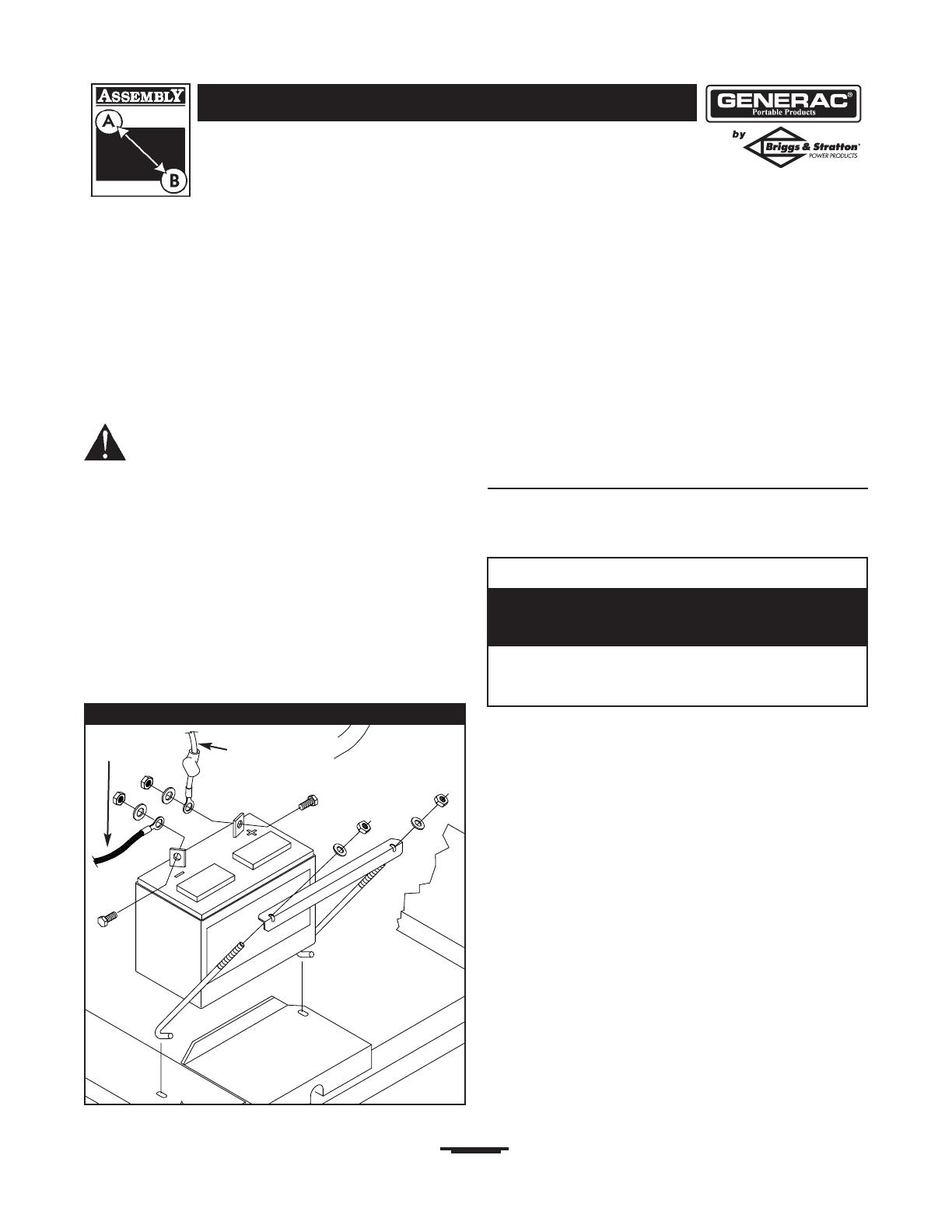
Install the battery as follows:
1. Find battery fasteners shipped loose in carton.
2. Set battery onto tray.
3. Retain battery to tray with one battery hold down
bracket, two J bolts, two flat washers and two hex nuts
(Figure 2).
4. Connect red battery cable from engine starter switch
to positive (+) terminal on battery with bolt, washer
and nut (Figure 2).
5. Connect black battery cable to negative (–) terminal
on battery with bolt, washer and nut (Figure 2).
6. Double check all connections to ensure they are in
correct locations and secure.
BEFORE STARTING THE
ENGINE
Add Engine Oil and Fuel
• Place generator on a level surface.
• Refer to engine owner’s manual and follow oil and fuel
recommendations and instructions.
NOTE: Check oil often during engine break–in. Refer to
engine owner’s manual for recommendations.
NOTE: The generator assembly rotates on a prelubricated
and sealed ball bearing that requires no additional
lubrication for the life of the bearing.
Figure 2 — Wire Connections
RED wire from
starter switch
BLACK wire
from engine
CAUTION
• Refer to engine manual for oil and fuel fill information.
• Damage to equipment resulting from failure to follow this
instruction will void warranty.
Any attempt to crank or start the engine before it has
been properly filled with the recommended oil will result
in equipment failure.

8
PowerBoss 8,000 Watt PowerMaster Generator
USING THE GENERATOR
System Ground
The generator has a system ground that connects the
generator frame components to the ground terminals on
the AC output receptacles.The system ground is connected
to the AC neutral wire (the neutral is bonded to the
generator frame).
Special Requirements
There may be Federal or State Occupational Safety and
Health Administration (OSHA) regulations, local codes, or
ordinances that apply to the intended use of the generator.
Please consult a qualified electrician, electrical inspector, or
the local agency having jurisdiction.
• In some areas, generators are required to be registered
with local utility companies.
• If the generator is used at a construction site, there may
be additional regulations which must be observed.
Connecting to a Building’s Electrical
System
Connections for standby power to a building’s electrical
system must be made by a qualified electrician.The
connection must isolate the generator power from utility
power, and must comply with all applicable laws and
electrical codes.
OPERATING THE
GENERATOR
Starting the Engine
Disconnect all electrical loads from the generator. Use the
following start instruction steps by numerical order:
1. Make sure unit is on a level surface.
IMPORTANT: Failure to start and operate unit on a level
surface will cause the unit not to start or shut down during
operation.
2. Turn the fuel valve to the “On” position (Figure 3).
3. Follow start instructions given in engine owner’s
manual.
NOTE: If engine starts after 3 pulls but fails to run, or if
unit shuts down during operation, make sure unit is on a
level surface and check for proper oil level in crankcase.
This unit may be equipped with a low oil protection device.
See engine manual.
Connecting Electrical Loads
• Let engine stabilize and warm up for a few minutes after
starting.
• Plug in and turn on desired 120 and/or 240 Volt AC,
single phase, 60 Hz electrical loads.
• When using generator for backup power, notify utility
company. Use approved transfer equipment to isolate
generator from electric utility.
• Use a ground fault circuit interrupter (GFCI) in any damp or
highly conductive area, such as metal decking or steel work.
• DO NOT touch bare wires or receptacles.
• DO NOT use generator with electrical cords which are worn,
frayed, bare or otherwise damaged.
• DO NOT operate generator in the rain.
• DO NOT handle generator or electrical cords while standing
in water, while barefoot, or while hands or feet are wet.
• DO NOT allow unqualified persons or children to operate or
service generator.
Generator produces powerful voltage.
Failure to isolate generator from power utility
can result in death or injury to electric utility
workers due to backfeed of electrical energy.
DANGER
• See “Don’t Overload Generator” on page 11.
• Start generator and let engine stabilize before connecting
electrical loads.
• Connect electrical loads in OFF position, then turn ON for
operation.
• Turn electrical loads OFF and disconnect from generator
before stopping generator.
Exceeding generators wattage/amperage capacity can
damage generator and/or electrical devices connected
to it.
CAUTION
Fuel Valve is shown
in the On position
Figure 3 — Fuel Valve

9
PowerBoss 8,000 Watt PowerMaster Generator
• DO NOT connect 240 Volt loads to 120 Volt receptacles.
• DO NOT connect 3–phase loads to generator.
• DO NOT connect 50 Hz loads to generator.
• DO NOT OVERLOAD THE GENERATOR. See
“Don’t Overload Generator” on page 11.
Stopping the Engine
1. Unplug all electrical loads from generator panel
receptacles. NEVER start or stop engine with electrical
devices plugged in and turned ON.
2. Let engine run at no-load for several minutes to
stabilize internal temperatures of engine and generator.
3. Turn engine off according to instructions given in the
engine owner’s manual.
4. Move fuel valve to “Off” position.
COLD WEATHER
OPERATION
Under certain weather conditions (temperatures below
40°F [4°C] and a high dew point), your generator may
experience icing of the carburetor and/or the crankcase
breather system.
Build a structure that will enclose three sides and the top
of the generator:
1. Make sure entire muffler-side of generator is exposed.
Note that your generator may appear different from
that shown in Figure 4.
2. Ensure a minimum of two feet clearance between open
side of box and nearest object.
3. Face exposed end away from wind and elements.
4. Enclosure should hold enough heat created by
generator to prevent problems.
RECEPTACLES
120/240 Volt AC, 50 Amp Receptacle
Use a NEMA 14–50 plug with this receptacle (Figure 5).
Connect a 4-wire cord set rated for 250 Volt AC loads at
50 Amps to the plug.
• NEVER attempt to power a device requiring more
amperage than generator or receptacle can supply.
• DO NOT overload the generator. See “Don’t Overload
Generator”.
Receptacles may be marked with rating value greater
than generator output capacity.
CAUTION
Figure 5 — 240 Volt AC, 50 Amp Receptacle
120 Volts
AC
120 Volts
AC
X (Hot)
Y (Hot)
240 Volts AC
Frame Ground
NEMA 14-50
W (Neutral)
Figure 4 — Permanent Cold Weather Shelter
Wind
• Operate generator ONLY outdoors.
• Keep at least 2 feet of clearance on all sides of generator for
adequate ventilation.
• DO NOT operate generator inside any building or enclosure,
including the generator compartment of a recreational vehicle (RV).
• Remove generator from shelter when temperature is above
40°F [4°C].
Running generator gives off carbon monoxide,
an odorless, colorless, poison gas.
Breathing carbon monoxide will cause nausea,
fainting or death.
DANGER

10
PowerBoss 8,000 Watt PowerMaster Generator
Use this receptacle to operate 240 Volt AC, 60 Hz, single
phase loads requiring up to 8,000 watts (8.0 kW) of power.
The outlet is protected by a 35 Amp push–to–reset circuit
breaker.
120/240 Volt AC, 30 Amp, Locking
Receptacle
Use a NEMA L14–30 plug with this receptacle. Connect a
4–wire cord set rated for 250 Volt AC loads at 30 Amps (or
greater) (Figure 6).You can use the same 4–wire cord if you
plan to run a 120 Volt load.
This receptacle powers 120/240 Volt AC, 60 Hz, single
phase loads requiring up to 3,600 watts of power at
30 Amps for 120 Volts; 7,200 watts of power (7.2 kW) at
30 Amps for 240 Volts.The outlet is protected by a 30 Amp
push–to–reset circuit breaker.
120 Volt AC, 30 Amp Locking
Receptacle
Use a NEMA L5–30 plug with this receptacle. Connect a
3–wire cord set rated for 125 Volt AC loads at 30 Amps to
the plug (Figure 7).
Use this receptacle to operate 120 Volt AC, 60 Hz, single
phase loads requiring up to 3,600 watts (3.6 kW) of power
at 30 Amps.The outlet is protected by a 30 Amp
push–to–reset circuit breaker.
120 Volt AC, 20 Amp, Duplex
Receptacle
Each receptacle (Figure 8) is protected against overload by
a 20 Amp push–to–reset circuit breaker.
Use each receptacle to operate 120 Volt AC, single–phase,
60 Hz electrical loads requiring up to 2,400 watts (2.4 kW)
at 20 Amps of current. Use cord sets that are rated for
125 Volt AC loads at 20 Amps (or greater).
Figure 7 — 120 Volt AC, 30 Amp, Locking Receptacle
3-Wire Cord Set
Neutral
120V
Hot
Ground (Green)
NEMA L5-30
Figure 6 — 120/240 Volt AC, 30 Amp Receptacle
4-Wire Cord Set
240V
120V
120V
W (Neutral)
X (Hot)
Y (Hot)
NEMA L14-30
Ground (Green)
Figure 8 — 120 Volt AC, 20 Amp, Duplex Receptacle
11
PowerBoss 8,000 Watt PowerMaster Generator
DON'T OVERLOAD
GENERATOR
Capacity
You must make sure your generator can supply enough
rated (running) and surge (starting) watts for the items you
will power at the same time. Follow these simple steps:
1. Select the items you will power at the same time.
2. Total the rated (running) watts of these items.This is
the amount of power your generator must produce to
keep your items running. See Figure 9.
3. Estimate how many surge (starting) watts you will
need. Surge wattage is the short burst of power
needed to start electric motor-driven tools or
appliances such as a circular saw or refrigerator.
Because not all motors start at the same time, total
surge watts can be estimated by adding only the
item(s) with the highest additional surge watts to the
total rated watts from step 2.
Example:
Total Rated (Running) Watts = 3075
Highest Additional Surge Watts = 1800
Total Generator Output Required = 4875
Power Management
To prolong the life of your generator and attached devices,
it is important to take care when adding electrical loads to
your generator.There should be nothing connected to the
generator outlets before starting its engine.The correct
and safe way to manage generator power is to sequentially
add loads as follows:
1. With nothing connected to the generator, start the
engine as described in this manual.
2. Plug in and turn on the first load, preferably the largest
load you have.
3. Permit the generator output to stabilize (engine runs
smoothly and attached device operates properly.
4. Plug in and turn on the next load.
5. Again, permit the generator to stabilize.
6. Repeat steps 4 and 5 for each additional load.
NEVER add more loads than the generator capacity.Take
special care to consider surge loads in generator capacity,
as described above.
*Wattages listed are approximate only. Check tool or
appliance for actual wattage.
Tool or Appliance
Rated (Running)
Watts
Additional Surge
(Starting) Watts
Window Air
Conditioner
1200 1800
Refrigerator 800 1600
Deep Freezer 500 500
Television 500 -
Light (75 Watts) 75 -
3075 Total
Running Watts
1800 Highest
Surge Watts
Tool or Appliance
Rated*
(Running)
Watts
Additional
Surge
(Starting)
Watts
Essentials
Light Bulb - 75 watt 75 -
Deep Freezer 500 500
Sump Pump 800 1200
Refrigerator/Freezer - 18 Cu. Ft. 800 1600
Water Well Pump - 1/3 HP 1000 2000
Heating/Cooling
Window AC - 10,000 BTU 1200 1800
Window Fan 300 600
Furnace Fan Blower - 1/2 HP 800 1300
Kitchen
Microwave Oven - 1000 Watt 1000 -
Coffee Maker 1500 -
Electric Stove - Single Element 1500 -
Hot Plate 2500 -
Family Room
DVD/CD Player 100 -
VCR 100 -
Stereo Receiver 450 -
Color Television - 27” 500 -
Personal Computer w/17” monitor 800 -
Other
Security System 180 -
AM/FM Clock Radio 300 -
Garage Door Opener - 1/2 HP 480 520
Electric Water Heater - 40 Gallon 4000 -
DIY/Job Site
Quartz Halogen Work Light 1000 -
Airless Sprayer - 1/3 HP 600 1200
Reciprocating Saw 960 960
Electric Drill - 1/2 HP 1000 1000
Circular Saw - 7 1/4” 1500 1500
Miter Saw - 10” 1800 1800
Table Planer - 6” 1800 1800
Table Saw/Radial Arm Saw - 10” 2000 2000
Air Compressor - 1-1/2 HP 2500 2500
Figure 9 - Wattage Reference Chart

SPECIFICATIONS
Maximum Surge Watts . . . . . . . . . . . . . . . .10,000 watts
Continuous Wattage Capacity . . . . . . . . . . .8,000 watts
Power Factor . . . . . . . . . . . . . . . . . . . . . . . . . . . . . .1.0
Rated Maximum Continuous AC Load Current:
At 120 Volts . . . . . . . . . . . . . . . . . . . . . . .66.6 Amps
At 240 Volts . . . . . . . . . . . . . . . . . . . . . . .33.3 Amps
Phase . . . . . . . . . . . . . . . . . . . . . . . . . . . . . . . . .1–phase
Rated Frequency . . . . . . . . . . . . . . . . . . . . . . .60 Hertz
Fuel Tank Capacity. . . . . . . . . . . . . . . . . . . 7 U.S. gallons
Shipping Weight . . . . . . . . . . . . . . . . . . . . . . . . .290 lbs.
GENERAL MAINTENANCE
RECOMMENDATIONS
The Owner/Operator is responsible for making sure that
all periodic maintenance tasks are completed on a timely
basis; that all discrepancies are corrected; and that the unit
is kept clean and properly stored. NEVER operate a
damaged or defective generator.
Engine Maintenance
See engine owner’s manual for instructions.
KEEP OUT OF REACH OF CHILDREN. DON'T
POLLUTE. CONSERVE RESOURCES. RETURN
USED OIL TO COLLECTION CENTERS.
Generator Maintenance
Generator maintenance consists of keeping the unit clean
and dry. Operate and store the unit in a clean dry
environment where it will not be exposed to excessive
dust, dirt, moisture or any corrosive vapors. Cooling air
slots in the generator must not become clogged with snow,
leaves or any other foreign material.
NOTE: DO NOT use a garden hose to clean generator.
Water can enter engine fuel system and cause problems. In
addition, if water enters generator through cooling air slots,
some of the water will be retained in voids and cracks of
the rotor and stator winding insulation.Water and dirt
buildup on the generator internal windings will eventually
decrease the insulation resistance of these windings.
Generator Cleaning
• Use a damp cloth to wipe exterior surfaces clean.
• Use a soft bristle brush to loosen caked on dirt or oil.
• Use a vacuum cleaner to pick up loose dirt and debris.
• Use low pressure air (not to exceed 25 psi) to blow
away dirt. Inspect cooling air slots and opening on
generator.These openings must be kept clean and
unobstructed.
12
PowerBoss 8,000 Watt PowerMaster Generator
• Used motor oil has been shown to cause skin cancer in
certain laboratory animals.
• Thoroughly wash exposed areas with soap and water.
Avoid prolonged or repeated skin contact with used
motor oil.
CAUTION
WHEN ADJUSTING OR MAKING REPAIRS TO YOUR
GENERATOR
• Disconnect the spark plug wire from the spark plug and place
the wire where it cannot contact spark plug.
Unintentional sparking can result in fire or
electric shock.
WARNING
• DO NOT expose generator to excessive moisture, dust, dirt,
or corrosive vapors.
• DO NOT insert any objects through cooling slots.
Improper treatment of generator can damage it and
shorten its life.
CAUTION

13
PowerBoss 8,000 Watt PowerMaster Generator
STORAGE
The generator should be started at least once every seven
days and allowed to run at least 30 minutes. If this cannot
be done and you must store the unit for more than
30 days, use the following guidelines to prepare it for
storage.
Generator Storage
• Clean the generator as outlined in “Generator Cleaning”.
• Check that cooling air slots and openings on generator
are open and unobstructed.
Engine Storage
See engine owner’s manual for instructions.
Other Storage Tips
• To prevent gum from forming in fuel system or on
essential carburetor parts, add fuel stabilizer into fuel
tank and fill with fresh gasoline. Run the unit for several
minutes to circulate the additive through the carburetor.
The unit and fuel can then be stored for up to
24 months. Fuel stabilizer can be purchased locally.
• DO NOT store gasoline from one season to another
unless it has been treated as described above.
• Replace fuel container if it starts to rust. Rust and/or dirt
in fuel can cause problems if it's used with this unit.
• Store unit in a clean and dry area.
• DO NOT place a storage cover over a hot generator.
• Let equipment cool for a sufficient time before placing the
cover on the equipment.
Storage covers can be flammable.
WARNING

14
PowerBoss 8,000 Watt PowerMaster Generator
TROUBLESHOOTING
Problem
No AC output is available, but
generator is running.
Generator runs good at no-load
but "bogs" down" when loads are
connected.
Generator will not start; or starts
and runs rough.
Generator shuts down during
operation.
Generator lacks power.
Cause
1. One of the circuit breakers is
open.
2. Fault in generator.
3. Poor connection or defective
cord set.
4. Connected device is bad.
1. Short circuit in a connected load.
2. Generator is overloaded.
3. Shorted generator circuit.
Low oil level.
1. Out of gasoline.
2. Low oil level.
Load is too high.
Correction
1. Reset circuit breaker.
2. Contact Authorized service
facility.
3. Check and repair.
4. Connect another device that is in
good condition.
1. Disconnect shorted electrical
load.
2. See "Don't Overload Generator".
3. Contact Authorized service
facility.
Fill crankcase to proper level or place
generator on level surface.
1. Fill fuel tank.
2. Fill crankcase to proper level or
place generator on level surface.
See "Don't Overload Generator".

15
PowerBoss 8,000 Watt PowerMaster Generator
NOTES
16
PowerBoss 8,000 Watt PowerMaster Generator
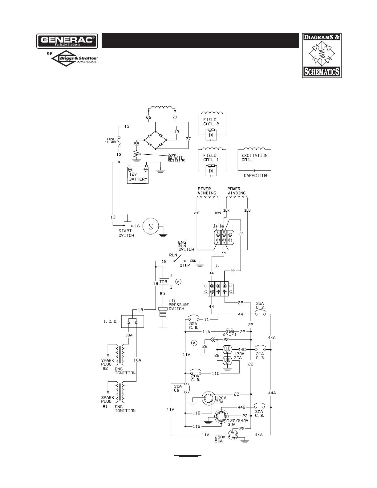
SCHEMATIC

17
PowerBoss 8,000 Watt PowerMaster Generator
WIRING DIAGRAM

18
PowerBoss 8,000 Watt PowerMaster Generator
EXPLODED VIEW – MAIN UNIT

19
PowerBoss 8,000 Watt PowerMaster Generator
Item Part # Description
1 NSP ENGINE
2 B189039GS CRADLE
3 B77304GS SUPPORT, Engine
4 77816GS DECAL, Caution Hot Muffler
5 93826GS DECAL, Start Instructions
6 92982GS DECAL, Danger
7 B4363GS CAP, Fuel Tank
8 48031CGS CLAMP, Hose
9 30340GS HOSE
10 193633GS ASSY,Tank, Fuel
(Includes Items 5, 6 & 39)
11 B4135GS PIN
12 83465GS GROMMET, Fuel Tank Mounting
13 96832GS CLAMP, Cable
14 23152GS SCREW
15 22237GS WASHER, Lock
16 22241GS NUT
17 75246GS SCREW
18 55934GGS CLAMP, Hose
19 J93074GS SUPPORT, Heat Shield
20 189302AGS ASSY,Wire, Starter
21 38353GS MOUNTS,Vibration
23 22145GS WASHER
24 B4986GS DECAL, Ground
25 26850GS WASHER
26 49820GS NUT, Nylok
27 187104GS WASHER, Nylon
28 39287GS SCREW
29 BB5586GS HANDLE (Includes Item 30)
30 B4605GS GRIP
31 189051GS ASSY, Control Panel (see page 21)
32 B2153GS SCREW
34 73054GS DECAL, Fuel Shut-Off
35 87680GS NUT,Wing
36 45757GS SCREW
37 49813GS NUT
38 19553621GS ASSY,Wire, Ground
39 192980GS KIT,Valve, Fuel
43 52856GS NUT, Lock
44 62265GS GROMMET
45 27482GS WASHER
46 42907GS SCREW
47 22131GS WASHER
48 52618GS SCREW
49 49226GS WASHER, Lock
Item Part # Description
50 B4794GS GROMMET, Generator Cover
51 47411GS SCREW
52 22473GS WASHER
53 76040GS SCREW
54 B4268GS ASSY,Alternator (see page 22)
55 J189091GS SHIELD, Heat
56 46476GS CAP, Plug
57 22511GS SCREW
58 22287GS SCREW
59 78289GS BRACKET, Starter Switch
60 77282GS SWITCH, Starter
61 189298BGS CABLE, Battery Positive
62 22127GS NUT
63 22097GS WASHER, Lock
64 185939GGS CABLE, Battery Negative
65 187856GS KIT, Hardware Tray and Battery
71 56893GS SCREW
72 91526GS SCREW
75 189286GS SCREW
76 189155GS WASHER
77 187049GS PLUG, Domed
78 192280GS HOSE BARB
Items Not Shown
189065GS MANUAL, Owners
MS5375 MANUAL, Engine
MS6497 SHEET, Instruction
193347GS KIT, Battery Hardware
807948 MUFFLER
807595 CLAMP, Muffler
805812 BRACKET, Muffler
392154 ARRESTOR, Spark
690661 SCREW
692056 BOLT
692359 SCREW
BB3061GS OIL, Bottle
43438GS PLUG, 240V, 30A
37806GS PLUG, 125V, 30A
193634GS KIT, Decal Service
Optional Accessories Not Included
84883GS Cord Wrap
43630GS 120/240 Volt AC 50 Amp Plug
PARTS LIST – MAIN UNIT

20
PowerBoss 8,000 Watt PowerMaster Generator
EXPLODED VIEW AND PARTS LIST – WHEEL KIT
Item Part # Description
1 191267JGS AXLE
2 B4966GS WHEEL
3 191265GS E-RING
4 22247GS WASHER
5 191413GS VIBE MOUNT, with Washer
6 22145GS WASHER
7 22413GS SCREW
8 39253GS SCREW
9 22129GS WASHER, Lock
10 B189085GS LEG, Support
11 192432GS NUT, Lock
/