KitchenAid KVWB400DSS Installation guide
- Category
- Cooker hoods
- Type
- Installation guide
This manual is also suitable for

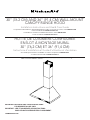
30" (76.2 CM) AND 36" (91.4 CM) WALL-MOUNT
CANOPY RANGE HOOD
Installation Instructions and Use & Care Guide
For questions about features, operation/performance, parts, accessories or service, call: 1-800-422-1230
or visit our website at www.kitchenaid.com.
In Canada, for assistance, installation and service, call: 1-800-807-6777
or visit our website at www.kitchenaid.ca.
HOTTE DE CUISINIÈRE CONFIGURÉE
EN ÎLOT À MONTAGE MURAL
30" (76,2 CM) ET 36" (91,4 CM)
Instructions d’installation et Guide d’utilisation et d’entretien
Au Canada, pour assistance, installation ou service composez le 1-800-807-6777
ou visitez notre site web à www.kitchenaid.ca.
Table of Contents/Table des matières.............................................................................2
LI3ZBD/W10674121E
IMPORTANT: READ AND SAVE THESE INSTRUCTIONS.
FOR RESIDENTIAL USE ONL
Y.
IMPOR
TANT : LIRE ET CONSERVER CES INSTRUCTIONS.
POUR UTILISA
TION RÉSIDENTIELLE UNIQUEMENT
.

2
TABLE OF CONTENTS TABLE DES MATIÈRES
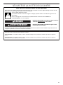
RANGE HOOD SAFETY
You can be killed or seriously injured if you don't immediately
You
can be killed or seriously injured if you don't
follow
All safety messages will tell you what the potential hazard is, tell you how to reduce the chance of injury, and tell you what can
happen if the instructions are not followed.
Your safety and the safety of others are very important.
We have provided many important safety messages in this manual and on your appliance. Always read and obey all safety
messages.
This is the safety alert symbol.
This symbol alerts you to potential hazards that can kill or hurt you and others.
All safety messages will follow the safety alert symbol and either the word “DANGER” or “WARNING.”
These words mean:
follow instructions.
instructions.
DANGER
WARNING
State of California Proposition 65 Warnings:
WARNING: This product contains one or more chemicals known to the State of California to cause cancer.
WARNING: This product contains one or more chemicals known to the State of California to cause birth defects or other
reproductive harm.
RANGE HOOD SAFETY .................................................................2
INSTALLATION REQUIREMENTS .................................................4
Tools and Parts ............................................................................. 4
Location Requirements ................................................................4
Venting Requirements ..................................................................5
Electrical Requirements ...............................................................6
INSTALLATION INSTRUCTIONS ...................................................7
Prepare Location ..........................................................................7
Install Range Hood ....................................................................... 8
Connect Vent System ..................................................................8
Make Electrical Connection .........................................................9
Install Vent Covers ........................................................................ 9
Complete Installation ...................................................................9
RANGE HOOD USE ......................................................................10
Range Hood Controls ................................................................10
RANGE HOOD CARE ...................................................................11
Cleaning .....................................................................................11
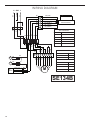
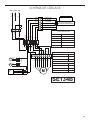
WIRING DIAGRAM .......................................................................12
ASSISTANCE OR SERVICE .........................................................13
In the U.S.A. ...............................................................................13
In Canada ...................................................................................13
Accessories ................................................................................13
WARRANTY ..................................................................................14
SÉCURITÉ DE LA HOTTE DE CUISINIÈRE ...............................15
EXIGENCES D'INSTALLATION ...................................................17
Outils et pièces ...........................................................................17
Exigences d’emplacement .........................................................18
Exigences concernant l’évacuation ...........................................19
Spécifications électriques ..........................................................20
INSTRUCTIONS D'INSTALLATION .............................................21
Préparation de l'emplacement ...................................................21
Installation de la hotte ................................................................22
Raccordement du circuit d'évacuation ...................................... 22
Raccordement électrique ...........................................................23
Installation des cache-conduits .................................................24
Achever l’installation ..................................................................24
UTILISATION DE LA HOTTE .......................................................25
Commandes de la hotte de cuisinière .......................................25
ENTRETIEN DE LA HOTTE .........................................................26
Nettoyage ...................................................................................26
SCHÉMA DE CÂBLAGE ...............................................................27
ASSISTANCE OU SERVICE .........................................................28
Au Canada ..................................................................................28
Accessoires ................................................................................28
GARANTIE .....................................................................................30

3
IMPORTANT SAFETY INSTRUCTIONS
READ AND SAVE THESE INSTRUCTIONS

4
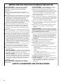
INSTALLATION REQUIREMENTS
Tools and Parts
Gather the required tools and parts before starting
installation. Read and follow the instructions provided
with any tools listed here.
Tools needed:
■ Level
■ Drill with 1
1
/
4
" (3.0 cm),
3
/
8
" (9.5 mm), and
5
/
16
" (7.9 mm)
drill bits
■ Pencil
■ Wire stripper or utility knife
■ Tape measure or ruler
■ Pliers
■ Caulking gun and weatherproof caulking compound
■ Vent clamps
■ Jigsaw or keyhole saw
■ Flat-blade screwdriver
■ Metal snips
■ Phillips screwdriver
■ Metric hex key set
Parts needed:
■ Home power supply cable
■
1
/
2
" (12.7 mm) UL Listed or CSA Approved strain relief
■ 3 UL Listed wire connectors
For vented installations, you will also need:
■ 1 wall or roof cap
■ Metal vent system
For non-vented (recirculating) installations, you will also
need:
■ Recirculation Kit Part Number W1027063 for non-vented
(recirculating) installations only. See the “Assistance or
Service” section to order.
■ Charcoal Filter Kit part number W1027068 for non-vented
(recirculating) installations only. See the “Assistance or
Service” section to order.
■ 6" (15.2 cm) diameter round metal vent duct - length required
is determined by ceiling height.
Parts supplied
Remove parts from packages. Check that all parts are included.
■ Hood canopy assembly with ventilator and light bulbs
installed
■ Vent transition with back draft dampers installed
■ Metal grease filter(s)
■ Vent cover support bracket
■ Mounting template
■ 2-piece vent cover
■ 4 - 3.5 x 9.5 mm screws
■ 4 - 3.5 x 6.5 mm screws
■ 2 - 2.9 x 6.5 mm screws
■ 6 - 5 x 45 mm mounting screws
■ 2 - 8 x 40 mm wall anchors
■ 4 - 10 x 60 mm wall anchors
■ 4 - 5.4 x 75 mm screws (for 10 x 60 mm wall anchors)
■ Torx
®†
T20
®†
adapter
Location Requirements
IMPORTANT: Observe all governing codes and ordinances.
Have a qualified technician install the range hood. It is the
installer’s responsibility to comply with installation clearances
specified on the model/serial/rating plate. The model/serial/
rating plate is located inside the range hood on the rear wall
of the range hood.
Canopy hood location should be away from strong draft areas,
such as windows, doors, and strong heating vents.
Cabinet opening dimensions that are shown must be used.
Given dimensions provide minimum clearance.
This range hood is recommended for use with cooktops with a
maximum total rating of 65,000 BTUs or less.
Grounded electrical outlet is required. See the “Electrical
Requirements” section.
The canopy hood is factory set for venting through the roof
or wall. For non-vented (recirculating) Installation, see “For
Non-vented (recirculating) Installations Only” in the “Connect
Vent System” section. The Recirculation Kit Part Number is
W1027063. Charcoal filters are also required for non-vented
(recirculating) installations. The Charcoal Filter Kit Part Number is
W1027068. See the “Assistance or Service” section to order.
All openings in ceiling and wall where canopy hood will be
installed must be sealed.
For Mobile Home Installations:
The installation of this range hood must conform to the
Manufactured Home Construction Safety Standards, Title 24
CFR, Part 328 (formerly the Federal Standard for Mobile Home
Construction and Safety, Title 24, HUD, Part 280) or when
such standard is not applicable, the standard for Manufactured
Home Installation 1982 (Manufactured Home Sites, Communities
and Setups) ANSI A225.1/NFPA 501A or latest edition, or with
local codes.
†
®
TORX and T20 are registered trademarks of Acument Intellectual Properties, LLC.

5
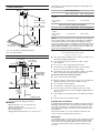
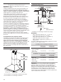
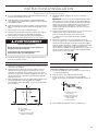
Product Dimensions
* For non-vented (recirculating) installations
** For vented installations
Cabinet Dimensions
* For non-vented (recirculating) installations
IMPORTANT:
Minimum distance “X”: 24" (61.0 cm) from
electric cooking surface.
Minimum distance “X”: 27" (68.6 cm) from
gas cooking surfaces.
Suggested maximum distance “X”: 36" (91.4 cm)
The chimneys can be adjusted for different ceiling heights. See
the following chart.
Vented Installations
Min. ceiling height Max. ceiling height
Electric cooking
surface
7' 5" (2.26 m) 9' 2" (2.79 m)
Gas cooking
surface
7' 8" (2.34 m) 9' 2" (2.79 m)
Non-vented (recirculating) Installations
Min. ceiling height Max. ceiling height
Electric cooking
surface
7' 5" (2.26 m) 9' 6" (2.9 m)
Gas cooking
surface
7' 8" (2.34 m) 9' 6" (2.9 m)
NOTE: The range hood chimneys are adjustable and designed to
meet varying ceiling or soffit heights, depending on the distance
“X” between the bottom of the range hood and the cooking
surface. For higher ceilings, a Stainless Steel Chimney Extension
Kit Part Number W10337357 is available from your dealer or an
authorized parts distributor. The chimney extension replaces the
upper chimney shipped with the range hood.
Venting Requirements
(venting models only)
■ Vent system must terminate to the outdoors, except for non-
vented (recirculating) installations.
■ Do not terminate the vent system in an attic or other
enclosed area.
■ Do not use 4" (10.2 cm) laundry-type wall cap.
■ Use metal vent only. Rigid metal vent is recommended.
Plastic or metal foil vent is not recommended.
■ The length of vent system and number of elbows should be
kept to a minimum to provide efficient performance.
For the most efficient and quiet operation:
■ Use no more than three 90° elbows.
■ Make sure there is a minimum of 24" (61 cm) of straight vent
between the elbows if more than 1 elbow is used.
■ Do not install 2 elbows together.
■ Use clamps to seal all joints in the vent system.
■ The vent system must have a damper. If the roof or wall
cap has a damper, do not use the damper supplied with the
range hood.
■ Use caulking to seal exterior wall or roof opening around the
cap.
■ The size of the vent should be uniform.
Cold Weather Installations:
An additional backdraft damper should be installed to minimize
backward cold air flow and a thermal break should be installed
to minimize conduction of outside temperatures as part of the
vent system. The damper should be on the cold air side of the
thermal break.
The break should be as close as possible to where the vent
system enters the heated portion of the house.
Makeup Air:
Local building codes may require the use of makeup air systems
when using ventilation systems greater than specified CFM of
air movement. The specified CFM varies from locale to locale.
Consult your HVAC professional for specific requirements in
your area.
10"
(25.4 cm)
20" (50.8 cm)
14¹⁄₈"
(35.9 cm)
7
¹⁄₄
"
(18.3 cm)
8
¹⁄₈
"
(20.7 cm)
*28⁷⁄₈" (72.6 cm) min.
42¹⁄₁₆" (106.9 cm) max.
**28³⁄₈" (72.0 cm) min.
38" (96.6 cm) max.
1¹₂" (4.0 cm)
30" (76.2 cm) or
36" (91.4 cm)
7¹⁄₄" (18.4 cm)
6⁵⁄₈" (16.8 cm)
2" (5.1 cm) min.
6" (15.2 cm) min.*
Centerline
Side
cabinet
Side
cabinet
Vent and power
supply cable
entry location
Cooking surface
15" (38.1 cm)
7³⁄₈" (18.8 cm)
“X”
bottom of
canopy
to cooking
surface
30" (76.2 cm) or
36" (91.4 cm)

6
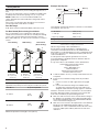
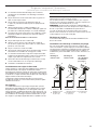
Venting Methods
This canopy hood is factory set for venting through the roof or
wall.
A 6" (15.2 cm) round vent system is needed for installation (not
included). The hood exhaust opening is 6" (15.2 cm) round.
NOTE: Flexible vent is not recommended. Flexible vent
creates back pressure and air turbulence that greatly reduce
performance.
Vent system can terminate either through the roof or wall. To
vent through a wall, a 90° elbow is needed.
Rear Discharge
A 90° elbow may be installed immediately above the hood.
For Non-Vented (Recirculating) Installations
If it is not possible to vent cooking fumes and vapors to the
outside, the hood can be used in the non-vented (recirculating)
version, using a Recirculation Kit (which includes charcoal
filters and a deflector). To order, see the “Assistance or Service”
section.
Roof Venting Wall Venting Non-Vented
(Recirculating)
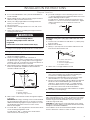
Calculating Vent System Length
To calculate the length of the system you need, add the
equivalent feet (meters) for each vent piece used in the system.
Vent Piece 6" (15.2 cm) Round
45° elbow
2.5 ft
(0.8 m)
90° elbow
5.0 ft
(1.5 m)
Maximum equivalent vent length is 35 ft (10.7 m).
Example Vent System
The following example falls within the maximum recommended
vent length of 35 ft (10.7 m).
1 - 90° elbow 5.0 ft (1.5 m)
1 - wall cap 0.0 ft (0.0 m)
8 ft (2.4 m) straight 8.0 ft (2.4 m)
Length of system 13.0 ft (3.9 m)
Electrical Requirements
Observe all governing codes and ordinances.
Ensure that the electrical installation is adequate and in
conformance with National Electrical Code, ANSI/NFPA 70
(latest edition), or CSA Standards C22.1-94, Canadian Electrical
Code, Part 1 and C22.2 No. 0-M91 (latest edition) and all local
codes and ordinances.
If codes permit and a separate ground wire is used, it is
recommended that a qualified electrician determine that the
ground path is adequate.
A copy of the above code standards can be obtained from:
National Fire Protection Association
1 Batterymarch Park
Quincy, MA 02169-7471
CSA International
8501 East Pleasant Valley Road
Cleveland, OH 44131-5575
■ A 120-volt, 60 Hz., AC-only, 15-amp, fused electrical circuit
is required.
■ If the house has aluminum wiring, follow the procedure
below:
1. Connect a section of solid copper wire to the pigtail
leads.
2. Connect the aluminum wiring to the added section
of copper wire using special connectors and/or tools
designed and UL Listed for joining copper to aluminum.
Follow the electrical connector manufacturer's recommended
procedure. Aluminum/copper connection must conform with
local codes and industry accepted wiring practices.
■ Wire sizes and connections must conform with the rating of
the appliance as specified on the model/serial/rating plate.
The model/serial/rating plate is located behind the left filter
on the rear wall of the range hood.
■ Wire sizes must conform to the requirements of the National
Electrical Code, ANSI/NFPA 70 (latest edition), or CSA
Standards C22. 1-94, Canadian Electrical Code, Part 1 and
C22.2 No. 0-M91 (latest edition) and all local codes and
ordinances.
A
A
B
B
B
A
A. Roof cap
B. 6" (15.2 cm)
round vent
A. Wall cap
B. 6" (15.2 cm)
round vent
A. Deflector
B. 6" (15.2 cm)
round vent
90 elbo
w
6 ft (1.8 m)
2 ft
(0.6 m)
Wall cap

7
INSTALLATION INSTRUCTIONS
Prepare Location
■ It is recommended that the vent system be installed before
hood is installed.
■ Before making cutouts, make sure there is proper clearance
within the ceiling or wall for exhaust vent.
■ Check your ceiling height and the hood height maximum
before you select your hood.
1. Disconnect power.
2. Determine which venting method to use: roof, wall, or non-
vented.
3. Select a flat surface for assembling the range hood. Place
covering over that surface.
4. Using 2 or more people, lift range hood onto covered surface.
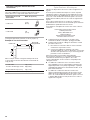
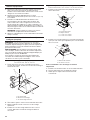
Range Hood Mounting Screws Installation
1. Determine and mark the centerline on the wall where the
canopy hood will be installed.
2. Select a mounting height between a minimum of
24" (61.0 cm) for an electric cooking surface, a minimum of
27" (68.6 cm) for a gas cooking surface, and a suggested
maximum of 36" (91.4 cm) above the range to the bottom of
the hood. Mark a reference line on the wall.
3. Tape template in place, aligning the template centerline and
bottom of template with hood bottom line and with the
centerline marked on the wall.
4. Mark centers of the fastener locations through the template
to the wall.
IMPORTANT: All canopy mounting screws must be installed
into wood where possible. If there is no wood to screw into,
additional wall framing supports may be required, or use the
(4) 10 x 60 mm wall anchors and 5.4 x 75 mm screws.
Remove the template.
5. For wood, drill
3
/
16
" (4.8 mm) pilot holes at all locations where
screws are being installed into wood.
For wall anchors, drill
7
/
16
" (10 mm) holes at all locations
where wall anchors are being used.
6. For wood, install (2) 5 x 45 mm mounting screws. Leave a
1
/
4
" (6.4 mm) gap between the wall and the back of the screw
head to slide range hood into place.
For wall anchors, install the 10 x 60 mm wall anchors and
install the 5.4 x 75 mm screws into the wall anchors. Tighten
until the wall anchors are secure. Back the screws out
1
/
4
" (6.4 mm).
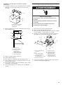
Vent Cover Support Bracket Installation
Installations using telescoping upper and lower vent cover
assembly
1. Position vent cover bracket on wall about
1
/
8
" (3.0 mm) away
from the ceiling.
2. Mark the hole locations.
3. Drill (2)
3
/
8
" (9.5 mm) holes for 8 x 40 mm wall anchors and
insert anchors flush with the wall.
4. Attach vent cover support bracket to wall.
Complete Preparation
1. Determine and make all necessary cuts in the wall for the
vent system. Install the vent system before installing the
hood. See the “Venting Requirements” section.
2. Determine the required height for the home power supply
cable and drill a 1
1
/
4
" (3.2 cm) hole at this location.
3. Run the home power supply cable according to the National
Electrical Code or CSA Standards and local codes and
ordinances. There must be enough
1
/
2
" conduit and wires
from the fused disconnect (or circuit breaker) box to make
the connection in the hood’s electrical terminal box.
NOTE: Do not reconnect power until installation is complete.
4. Use caulk to seal all openings.
Install In-Line Smart Kit - Optional
NOTE: Your range hood can work with either an internal or an
inline (external) blower motor system. An optional In-Line Smart
Kit (purchased separately) allows the blower motor that comes
with this range hood to be installed in a location other than
inside the range hood cavity.
CAUTION: To reduce the risk of fire and electric shock, install
this range hood only with the In-Line Smart Kit manufactured by
Whirlpool, Part Number W10692945.
For installation see the In-Line Smart Kit installation instructions.
See the “Assistance or Service” section to order.
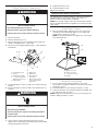
WARNING
Excessive Weight Hazard
Use two or more people to move and install
range hood.
Failure to do so can result in back or other injury.
Vertical Centerline
C
L
LLAW RAER
ETALPMET GNITNUOM
EGDE MOTTOB NGILA
ENIL LICNEP HTIW
MOTTOB GNITACIDNI
DOOH EHT FO
thgieH noitallatsnI
TROPPUS LLAW RAER RO SDUTS HGUORHT SELOH TOLIP "61/3 )OWT( 2 LLIRD
eniL latnoziroH
A
C
B
A. Centerline
B. Fastener locations
C. Mounting height reference
¹⁄₄
"
(6.4 mm)
A
B
C
D
A. 8 x 40 mm wall anchors
B. Centerline on wall
C. Vent cover support bracket
D. 5 x 45 mm screws

8
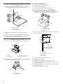
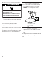
Install Range Hood
1. Using 2 or more people, hang range hood on 2 mounting
screws through the mounting slots on back of hood.
2. Remove the grease filter. See the “Range Hood Care”
section.
3. Level the range hood and tighten upper mounting screws.
4. Install (2) 5 x 45 mm lower mounting screws and tighten.
Use the optional wall anchors if needed.
Connect Vent System
1. Install the spacer and the outlet plate on top of the hood.
2. Install transition on top of hood (if removed for shipping) with
(2) 3.5 x 9.5 mm sheet metal screws.
For vented installations only:
1. Fit vent system over transition piece.
2. Seal connection with clamps.
3. Check that backdraft dampers work properly.
For non-vented (recirculating) installation only:
1. Assemble the air deflector with the duct cover bracket with 2
assembly screws provided with the Recirculation Kit.
2. Measure from the bottom of the air deflector to the bottom
of the hood outlet.
3. Cut the duct to the measured size “X.”
4. Remove the air deflector.
5. Slide the duct onto the bottom of the air deflector.
6. Place the assembled air deflector and duct over the exhaust
outlet from the hood.
7. Reassemble the air deflector to the duct cover bracket with
2 assembly screws.
8. Seal connections with vent clamps.
A
B
C
A. Mounting screws
B. Mounting slots
C. Lower mounting screws
A
D
B
D
C
A. Spacer
B. Outlet plate
C. (2) 3.5 x 9.5 mm screws
D. (4) 3.5 x 6.5 mm screws
B
A
A. Vent transition
B. 3.5 x 9.5 mm screw
A
C
B
B
A. Vent cover bracket
B. 2.9 x 6.5 mm screws
C. Deflector
X
A
C
D
B
E
A. Air deflector
B. Vent clamp
C. X = length to cut vent duct
D. Vent duct
E. Exhaust outlet

9
Make Electrical Connection
1. Disconnect power.
2. Remove terminal box cover.
3. Remove the knockout in the terminal box and install a UL
Listed or CSA Approved
1
/
2
" strain relief.
4. Run home power supply wiring through
1
/
2
" strain relief into
terminal box.
5. Use UL Listed wire connectors and connect white wires (B)
together.
6. Use UL Listed wire connectors and connect black wires (C)
together.
7. Connect green (or bare) ground wire from home power
supply to the 2 yellow-green ground wires (D) in terminal box
using UL Listed wire connectors.
8. Tighten strain relief screw.
9. Install terminal box cover.
10. Reconnect power.
Optional Power Cord Kit Installations
For optional power cord kit installations, follow the instructions
supplied with the power cord kit. See the “Assistance or
Service” section for information on ordering.
NOTE: Use only with range hood cord connection kits that have
been investigated and found acceptable for use with this model
range hood.
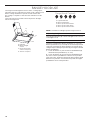
Install Vent Covers
1. When using both upper and lower vent covers, push lower
cover down onto hood and lift upper cover to ceiling and
install with (2) 2.9 x 6.5 mm screws.
NOTE: For vented installations, the upper vent cover may be
reversed to hide slots.
Complete Installation
1. For non-vented (recirculating) installations only, install
charcoal filters over grille on blower housing. See the “Range
Hood Care” section.
2. Install metal filters. See the “Range Hood Care” section.
3. Check the operation of the range hood blower and light. See
the “Range Hood Use” section.
NOTE: To get the most efficient use from your new range hood,
read the “Range Hood Use” section.
WARNING
Electrical Shock Hazard
Disconnect power before servicing.
Replace all parts and panels before operating.
Failure to do so can result in death or electrical shock.
A
B
C
D
F
B
E
G
H
I
A. Terminal box cover
B. Screws
C. Home power supply
D
1
/
2
" UL Listed or CSA
Approved strain relief
E. Terminal box
F. Black wires
G. White wires
H. UL Listed wire
connectors
I. Green (or bare) wires
connected to yellow-
green wires
WARNING
Electrical Shock Hazard
Electrically ground blower.
Connect ground wire to green and yellow ground wire
in terminal box.
Failure to do so can result in death or electrical shock.
A
B
C
C
D
A. Upper vent cover
B. Lower vent cover
C. 2.9 x 6.5 mm screws
D. Bracket

10
RANGE HOOD USE
The range hood is designed to remove smoke, cooking vapors,
and odors from the cooktop area. For best results, start the hood
before cooking and allow it to operate several minutes after
the cooking is complete to clear all smoke and odors from the
kitchen.
The hood controls are located on the front panel on the right
side of the range hood.
Range Hood Controls
NOTE: Control buttons will light up when range hood is on.
Operating the light
The Light On/Off button (A) controls both lights. Press once for
on and again for off.
Operating the blower
The blower On/Off button (B) turns the blower on or off. The
blower Speed buttons (C, D, and E) set the desired speed and
control the sound level for quiet operation. The speed can be
changed anytime during fan operation by pressing the desired
blower speed button.
1. To turn the blower on, press the blower On/Off button (B)
and the desired speed button (C, D, or E).
2. To turn the blower off, press the blower On/Off button (B).
Any of the 3 blower speed buttons can be in the on position
at the same time. The blower will operate at the highest speed
button that is pushed in. For lower blower speeds, the higher
speed buttons must not be pushed in.
A
B
C
D
A. LED lights
B. Blower and light
controls
C. Grease filter (behind
stainless steel panel)
D. Stainless steel panel
ABCDE
A. Light On/Off button
B. Blower On/Off button
C. Blower speed minimum button
D. Blower speed medium button
E. Blower speed maximum button

11
RANGE HOOD CARE
Cleaning
IMPORTANT: Clean the hood and grease filters frequently
according to the following instructions. Replace grease filters
before operating hood.
Exterior Surfaces
To avoid damage to the exterior surface, do not use steel wool
or soap-filled scouring pads.
Always wipe dry to avoid water marks.
Cleaning Method
■ Liquid detergent soap and water, or all-purpose cleanser
■ Wipe with damp soft cloth or nonabrasive sponge, then rinse
with clean water and wipe dry.
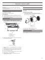
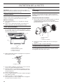
Metal Grease Filter
1. Open the stainless steel panel. Grasp panel at the front
corners and pull down to disengage the 2 catch pins from
the spring catches. The panel is attached at the rear and will
rotate down.
2. Remove each filter by pulling the spring release handle and
then pulling down the filter.
3. Wash metal filters as needed in dishwasher or hot detergent
solution.
4. Reinstall the filter by making sure the spring release handles
are toward the front. Insert aluminum filter into upper track.
5. Push in spring release handle.
6. Push up on metal filter and release handle to latch into place.
7. Repeat steps 1-5 for the other filter.
8. Close the stainless steel panel. Engage the 2 pins in the
spring catches to secure.
Non-Vented (Recirculating) Installation Filters
The charcoal filter is not washable. It should last up to 6 months
with normal use. Replace with Charcoal Filter Kit Number
W10272068.
To Replace Charcoal Filter:
1. Cover the grille that covers the blower motor with the
charcoal filter so that the slots on the filter correspond to the
pins on the sides of the motor grille.
2. Turn the charcoal filter clockwise to lock it.
3. Repeat steps 1-2 on the other filter.
Replacing a Led Lamp
The LED lights are replaceable by a service technician only.
See the “Warranty” section for service contact information.
A
B
C
D
A. Metal filters
B. Stainless steel panel
C. Catch pins (2)
D. Spring catches (2)
A
A. Spring release handle
A
B
C
A. Charcoal filter
B. Pins
C. Blower motor
Page is loading ...

13
ASSISTANCE OR SERVICE
If you need service:
Please refer to the warranty page in this manual.
If you need replacement parts:
If you need to order replacement parts, we recommend that
you use only factory specified parts. Factory specified parts will
fit right and work right because they are made with the same
precision used to build every new appliance.
To locate factory specified replacement parts in your area, call
the following customer assistance telephone number or your
nearest designated service center.
In the U.S.A.
Call the KitchenAid Customer eXperience Center toll free:
1-800-422-1230 or visit our website at www.kitchenaid.com.
Our Consultants Provide Assistance With:
■ Scheduling of service. KitchenAid designated service
technicians are trained to fulfill the product warranty and
provide after-warranty service anywhere in the United States.
■ Features and specifications on our full line of appliances.
■ Referrals to local dealers.
■ Installation information.
■ Use and maintenance procedures.
■ Accessory and repair parts sales.
■ Specialized customer assistance (Spanish speaking, hearing
impaired, limited vision, etc.).
For Further Assistance:
If you need further assistance, you can write to KitchenAid with
any questions or concerns at:
KitchenAid Brand Home Appliances
Customer eXperience Center
553 Benson Road
Benton Harbor, MI 49022-2692
Please include a daytime phone number in your correspondence.
In Canada
Call the Whirlpool Canada LP Customer eXperience Centre toll
free: 1-800-807-6777 or visit our website at www.kitchenaid.ca.
Our Consultants Provide Assistance With:
■ Scheduling of service. KitchenAid appliances designated
service technicians are trained to fulfill the product warranty
and provide after-warranty service anywhere in Canada.
■ Features and specifications on our full line of appliances.
■ Referrals to local dealers.
■ Use and maintenance procedures.
■ Accessory and repair parts sales.
For Further Assistance:
If you need further assistance, you can write to Whirlpool
Canada LP with any questions or concerns at:
Customer eXperience Centre
Whirlpool Canada LP
200 - 6750 Century Ave.
Mississauga, Ontario L5N 0B7
Please include a daytime phone number in your correspondence.
Accessories
Charcoal Filter Kit
(for non-vented installations only)
Order Part Number W10272068
Recirculation Kit
(for non-vented installations only)
Order Part Number W10272063
Chimney Extension Kit
Order Part Number W10337357
Power Cord Kit
Order Part Number W10613691
In-Line Smart Kit
Order Part Number W10692945

14
11/14
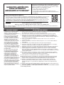
IF YOU NEED SERVICE:
1. Before contacting us to arrange service, please determine whether your product requires repair. Some
questions can be addressed without service. Please take a few minutes to review the Troubleshooting
or Problem Solver section of the Use and Care Guide, scan the QR code on the right to access
additional resources, or visit http://kitchenaid.custhelp.com.
2. All warranty service is provided exclusively by our authorized KitchenAid Service Providers. In the U.S.
and Canada, direct all requests for warranty service to:
KitchenAid Customer eXperience Center
In the U.S.A., call 1-800-422-1230. In Canada, call 1-800-807-6777.
If outside the 50 United States or Canada, contact your authorized KitchenAid dealer to determine whether another warranty applies.
KITCHENAID
®
MAJOR APPLIANCE
LIMITED WARRANTY
ATTACH YOUR RECEIPT HERE. PROOF OF PURCHASE IS
REQUIRED TO OBTAIN WARRANTY SERVICE.
Please have the following information available when you call the
Customer eXperience Center:
■ Name, address and telephone number
■ Model number and serial number
■ A clear, detailed description of the problem
■ Proof of purchase including dealer or retailer name and address
ONE YEAR LIMITED WARRANTY
WHAT IS COVERED WHAT IS NOT COVERED
For one year from the date of purchase,
when this major appliance is installed,
operated and maintained according to
instructions attached to or furnished
with the product, KitchenAid brand
of Whirlpool Corporation or Whirlpool
Canada LP (hereafter “KitchenAid”) will
pay for Factory Specified Replacement
Parts and repair labor to correct
defects in materials or workmanship
that existed when this major appliance
was purchased, or at its sole discretion
replace the product. In the event of
product replacement, your appliance
will be warranted for the remaining term
of the original unit’s warranty period.
YOUR SOLE AND EXCLUSIVE
REMEDY UNDER THIS LIMITED
WARRANTY SHALL BE PRODUCT
REPAIR AS PROVIDED HEREIN.
Service must be provided by a
KitchenAid designated service
company. This limited warranty is valid
only in the United States or Canada
and applies only when the major
appliance is used in the country in
which it was purchased. This limited
warranty is effective from the date of
original consumer purchase. Proof
of original purchase date is required
to obtain service under this limited
warranty.
1. Commercial, non-residential, multiple-family use, or use inconsistent with published user,
operator or installation instructions.
2. In-home instruction on how to use your product.
3. Service to correct improper product maintenance or installation, installation not in accordance
with electrical or plumbing codes or correction of household electrical or plumbing (i.e. house
wiring, fuses or water inlet hoses).
4. Consumable parts (i.e. light bulbs, batteries, air or water filters, preservation solutions, etc.).
5. Defects or damage caused by the use of non-genuine KitchenAid parts or accessories.
6. Conversion of products from natural gas or L.P. gas.
7. Damage from accident, misuse, abuse, fire, floods, acts of God or use with products not
approved by KitchenAid.
8. Repairs to parts or systems to correct product damage or defects caused by unauthorized
service, alteration or modification of the appliance.
9. Cosmetic damage including scratches, dents, chips, and other damage to the appliance
finishes unless such damage results from defects in materials and workmanship and is
reported to KitchenAid within 30 days.
10. Discoloration, rust or oxidation of surfaces resulting from caustic or corrosive environments
including but not limited to high salt concentrations, high moisture or humidity or exposure to
chemicals.
11. Food or medicine loss due to product failure.
12. Pick-up or delivery. This product is intended for in-home repair.
13. Travel or transportation expenses for service in remote locations where an authorized
KitchenAid servicer is not available.
14. Removal or reinstallation of inaccessible appliances or built-in fixtures (i.e. trim, decorative
panels, flooring, cabinetry, islands, countertops, drywall, etc.) that interfere with servicing,
removal or replacement of the product.
15. Service or parts for appliances with original model/serial numbers removed, altered or not
easily determined.
The cost of repair or replacement under these excluded circumstances shall be borne by the
customer.
DISCLAIMER OF IMPLIED WARRANTIES
IMPLIED WARRANTIES, INCLUDING ANY IMPLIED WARRANTY OF MERCHANTABILITY OR IMPLIED WARRANTY OF FITNESS FOR A
PARTICULAR PURPOSE, ARE LIMITED TO ONE YEAR OR THE SHORTEST PERIOD ALLOWED BY LAW. Some states and provinces do not
allow limitations on the duration of implied warranties of merchantability or fitness, so this limitation may not apply to you. This warranty gives
you specific legal rights, and you also may have other rights that vary from state to state or province to province.
DISCLAIMER OF REPRESENTATIONS OUTSIDE OF WARRANTY
KitchenAid makes no representations about the quality, durability, or need for service or repair of this major appliance other than the
representations contained in this warranty. If you want a longer or more comprehensive warranty than the limited warranty that comes with this
major appliance, you should ask KitchenAid or your retailer about buying an extended warranty.
LIMITATION OF REMEDIES; EXCLUSION OF INCIDENTAL AND CONSEQUENTIAL DAMAGES
YOUR SOLE AND EXCLUSIVE REMEDY UNDER THIS LIMITED WARRANTY SHALL BE PRODUCT REPAIR AS PROVIDED HEREIN.
KITCHENAID SHALL NOT BE LIABLE FOR INCIDENTAL OR CONSEQUENTIAL DAMAGES. Some states and provinces do not allow the
exclusion or limitation of incidental or consequential damages, so these limitations and exclusions may not apply to you. This warranty gives
you specific legal rights, and you also may have other rights that vary from state to state or province to province.
http://kitchenaid.custhelp.com
Page is loading ...
Page is loading ...
Page is loading ...
Page is loading ...
Page is loading ...
Page is loading ...
Page is loading ...
Page is loading ...
Page is loading ...
Page is loading ...
Page is loading ...
Page is loading ...
Page is loading ...
Page is loading ...
Page is loading ...
Page is loading ...
Page is loading ...
Page is loading ...
-
 1
1
-
 2
2
-
 3
3
-
 4
4
-
 5
5
-
 6
6
-
 7
7
-
 8
8
-
 9
9
-
 10
10
-
 11
11
-
 12
12
-
 13
13
-
 14
14
-
 15
15
-
 16
16
-
 17
17
-
 18
18
-
 19
19
-
 20
20
-
 21
21
-
 22
22
-
 23
23
-
 24
24
-
 25
25
-
 26
26
-
 27
27
-
 28
28
-
 29
29
-
 30
30
-
 31
31
-
 32
32


KitchenAid KVWB400DSS Installation guide
- Category
- Cooker hoods
- Type
- Installation guide
- This manual is also suitable for
Ask a question and I''ll find the answer in the document
Finding information in a document is now easier with AI
in other languages
Related papers
-
KitchenAid KVWB400DSS Owner's manual
-
KitchenAid KVWB400DSS Owner's manual
-
-
-
KitchenAid KVWB606DSS User manual
-
KitchenAid KVWB600DSS Installation guide
-
-
-
KitchenAid KVIB602DSS Installation guide
-
Other documents
-
Whirlpool WVW75UC6DS Owner's manual
-
-
Whirlpool GXW7336DXS Owner's manual
-
Whirlpool WVW53UC0FS Installation guide
-
-
-
-
-
-