ProSoft Technology A-J1939R/B Quick start guide
- Type
- Quick start guide

Revision 1.1
01/2023
Document No. D155-011 Page 1 of 4
J1939 Router/B
Quick Start Guide
A-J1939R/B
NOTE: Before installing, configuring, operating, or maintaining Aparian products, please review this
information and the information located on www.aparian.com for the latest software,
documentation, and installation files specific to your Aparian product.
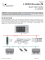
INTRODUCTION
This quick start guide provides an basic overview of the installation, operation, and diagnostics of the
Aparian J1939 Router Series B module. The J1939 Router/B provides intelligent data routing between
either EtherNet/IP or Modbus TCP/RTU and a J1939 network. This allows the user to integrate J1939
devices into a Rockwell Automation Logix platform (e.g., ControlLogix or CompactLogix) or any
Modbus Client or Server device with minimal effort.

Revision 1.1
01/2023
Document No. D155-011 Page 2 of 4
REQUIRED SOFTWARE
The J1939 Router/B requires Aparian Slate software to setup and configure. The software installation
can be found at www.aparian.com/software/slate.
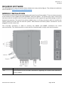
MODULE INSTALLATION
The module has two Ethernet ports located at the lower front of the module. There are also two ports
at the bottom of the module for RS232/RS485 serial and power. The power port uses a three-way
connector which is used for the DC power supply positive and negative (or ground) voltage as well as
the earth connection. The at the front of the module there is a 5-way connector which is used for the
J1939 network and can also be used for power. Both bottom and front power connectors can be
plugged in at the same time.
The nine-way connector is used to connect the RS232 and RS485 conductors for serial
communication. The shield terminal can be used for shielded cable in high noise environments.
LED
Description
Ok
The module LED will provide information regarding the system-level operation
of the module.

Revision 1.1
01/2023
Document No. D155-011 Page 3 of 4
If the LED is red, then the module is not operating correctly. For example, if the
module application firmware has been corrupted or there is a hardware fault the
module will have a red Module LED.
If the LED is green (flashing), then the module has booted and is running correctly
without any application configuration loaded.
If the LED is green (solid), then the module has booted and is running correctly
with application configuration loaded.
A / B
The Ethernet LED will light up when an Ethernet link has been detected (by
plugging in a connected Ethernet cable). The LED will flash every time traffic was
detected. This module has two Ethernet ports A and B. Each LEDs represents
each specific port.
Act
The Act LED indicates if the module is currently in an active state where the
primary interface is operational.
Solid Green – The local J1939 Router/B is in an operating state.
Off - The local J1939 Router/B is not in an operating state.
CAN
The CAN LED indicates the activity on the J1939 network.
Flashing Red – A corrupted or incorrect J1939 packet was received.
Flashing Green – A valid J1939 packet was received or sent.
Off – No J1939 packets are being received or sent.
Aux
The Aux LED will flash each time there was activity on any of the primary
interfaces.
Flashing Red – A corrupted or incorrect packet was received on one of the
Primary Interfaces (EtherNet/IP, Modbus TCP/RTU232/RTU485).
Flashing Green – A valid packet was received on one of the Primary Interfaces
(EtherNet/IP, Modbus TCP/RTU232/RTU485).
Off – No activity.
J1939 NETWORK TERMINATION
All CAN networks need to be terminated at the extremities (start and end point) of the
communication conductor. The termination for the CAN network can be enabled/disabled via the
module configuration. Enabling the termination will connect an internal 120 Ohm resistor across the
positive (+) and negative (-) conductors of the CAN network.
ELECTRICAL AND ENVIRONMENTAL
Specification
Rating
Power requirements
Input: 10 – 32V DC,
Power consumption
2.2 W (Max.)
Current: 180 mA @ 10 V
Current: 85 mA @ 24 V
Temperature
-20 – 70 °C

Revision 1.1
01/2023
Document No. D155-011 Page 4 of 4
STUDIO 5000 CONFIGURATION
The module must be added to the Logix IO tree using a EDS AOP (Logix v21+).
NORTH AMERICAN HAZARDOUS LOCATION APPROVAL
SUITABLE FOR USE IN CLASS I, DIVISION 2, GROUPS A, B, C AND D HAZARDOUS LOCATIONS, OR
NONHAZARDOUS LOCATIONS ONLY.
WARNING - EXPLOSION HAZARD - DO NOT DISCONNECT EQUIPMENT WHILE THE CIRCUIT IS LIVE OR
UNLESS THE AREA IS KNOW TO BE FREE OF IGNITABLE CONCENTRATIONS.
WARNING - EXPLOSION HAZARD - SUBSTITUTION OF ANY COMPONENT MAY IMPAIR SUITABILITY FOR
CLASS I, DIVISION 2.
For professional users in the European Union
If you wish to discard electrical and electronic equipment (EEE), please contact your dealer
or supplier for further information.
WARNING – Cancer and reproductive harm – www.p65warnings.ca.gov
ADDITIONAL INFORMATION
The following resources contain additional information that can assist the user with the module
installation and operation.
Resource
Link
Slate Installation
www.aparian.com/software/slate
J1939 Router User Manual
J1939 Router Datasheet
https://www.aparian.com/products/j1939Routerb
Ethernet wiring standard
www.cisco.com/c/en/us/td/docs/video/cds/cde/cd
e205_220_420/installation/guide/cde205_220_420
_hig/Connectors.html
SAE J1939 Standards
http://www.sae.org/standardsdev/groundvehicle/j
1939a.htm
Slate Installation
www.aparian.com/software/slate
SUPPORT
Technical support will be provided via the Web (in the form of user manuals, FAQ, datasheets etc.) to
assist with installation, operation, and diagnostics.
For additional support the user can use either of the following:
Contact Us web link
https://www.prosoft-technology.com/Services-
Support/Customer-Support
Support email
-
 1
1
-
 2
2
-
 3
3
-
 4
4


ProSoft Technology A-J1939R/B Quick start guide
- Type
- Quick start guide
Ask a question and I''ll find the answer in the document
Finding information in a document is now easier with AI