
COM-HPC-sIDH User’s Guide PICMG COM-HPC R1.1
Page 1 Copyright © 2023 ADLINK Technology, Inc.
COM-HPC-sIDH
Revision: Rev. 0.1
Date: 2023-05-05
Part Number: 50M-00133-1000
User’s Guide

COM-HPC-sIDH User’s Guide PICMG COM-HPC R1.1
Page 2 Copyright © 2023 ADLINK Technology, Inc.
Revision History
Revision
Description
Date
Author
0.1
Preliminary release
2023-05-05
CC

COM-HPC-sIDH User’s Guide PICMG COM-HPC R1.1
Page 3 Copyright © 2023 ADLINK Technology, Inc.
Preface
Disclaimer
Information in this document is provided in connection with ADLINK products. No license, express or implied, by estoppel or otherwise, to any
intellectual property rights is granted by this document. Except as provided in ADLINK´s Terms and Conditions of Sale for such products, ADLINK
assumes no liability whatsoever, and ADLINK disclaims any express or implied warranty, relating to sale and/or use of ADLINK products including
liability or warranties relating to fitness for a particular purpose, merchantability, or infringement of any patent, copyright or other intellectual property
right. If you intend to use ADLINK products in or as medical devices, you are solely responsible for all required regulatory compliance, including, without
limitation, Title 21 of the CFR (US), Directive 2007/47/EC (EU), and ISO 13485 & 14971, if any. ADLINK may make changes to specifications and product
descriptions at any time, without notice.
Environmental Responsibility
ADLINK is committed to fulfil its social responsibility to global environmental preservation through compliance with the European Union's Restriction of
Hazardous Substances (RoHS) directive and Waste Electrical and Electronic Equipment (WEEE) directive. Environmental protection is a top priority for
ADLINK. We have enforced measures to ensure that our products, manufacturing processes, components, and raw materials have as little impact on the
environment as possible. When products are at their end of life, our customers are encouraged to dispose of them in accordance with the product
disposal and/or recovery programs prescribed by their nation or company.
California Proposition 65 Warning: This product can expose you to chemicals including acrylamide, arsenic, benzene, cadmium, Tris(1,3-
dichloro-2-propyl)phosphate (TDCPP), 1,4-Dioxane, formaldehyde, lead, DEHP, styrene, DINP, BBP, PVC, and vinyl materials, which are known
to the State of California to cause cancer, and acrylamide, benzene, cadmium, lead, mercury, phthalates, toluene, DEHP, DIDP, DnHP, DBP,
BBP, PVC, and vinyl materials, which are known to the State of California to cause birth defects or other reproductive harm. For more
information go to www.P65Warnings.ca.gov.
Trademarks
Product names mentioned herein are used for identification purposes only and may be trademarks / registered trademarks of respective companies.
Copyright © 2023 ADLINK Technology Incorporated
This document contains proprietary information protected by copyright. All rights are reserved. No part of this manual may be reproduced by any
mechanical, electronic, or other means in any form without prior written permission of the manufacturer.

COM-HPC-sIDH User’s Guide PICMG COM-HPC R1.1
Page 4 Copyright © 2023 ADLINK Technology, Inc.
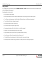
Safety Instructions
For user safety, please read and follow all Instructions, WARNINGs, CAUTIONs, and NOTEs marked in this manual and on the associated equipment
before handling/operating the equipment.
Read these safety instructions carefully.
• Keep this manual for future reference.
• Read the specifications section of this manual for detailed information on the operating environment of this equipment.
• Turn off power and unplug any power cords/cables when installing/mounting or un-installing/removing equipment.
• To avoid electrical shock and/or damage to equipment:
• Keep equipment away from water or liquid sources;
• Keep equipment away from high heat or high humidity;
• Keep equipment properly ventilated (do not block or cover ventilation openings);
• Make sure to use recommended voltage and power source settings;
• Always install and operate equipment near an easily accessible electrical socket outlet;
• Secure the power cord (do not place any object on/over the power cord);
• Only install/attach and operate equipment on stable surfaces and/or recommended mountings;
• If the equipment will not be used for long periods of time, turn off the power source and unplug the equipment.

COM-HPC-sIDH User’s Guide PICMG COM-HPC R1.1
Page 5 Copyright © 2023 ADLINK Technology, Inc.
Conventions
The following conventions may be used throughout this manual, denoting special levels of information
Note: This information adds clarity or specifics to text and illustrations.
Caution: This information indicates the possibility of minor physical injury, component damage, data loss, and/or program corruption.
Warning: This information warns of possible serious physical injury, component damage, data loss, and/or program corruption.

COM-HPC-sIDH User’s Guide PICMG COM-HPC R1.1
Page 6 Copyright © 2023 ADLINK Technology, Inc.
Getting Service
Ask an Expert: https://www.adlinktech.com/en/Askanexpert
ADLINK Technology, Inc.
No. 66, Huaya 1st Rd., Guishan District, Taoyuan City 333411, Taiwan
Tel: +886-3-216-5088
Fax: +886-3-328-5706
Email: service@adlinktech.com
Ampro ADLINK Technology, Inc.
6450 Via Del Oro, San Jose, CA 95119-1208, USA
Tel: +1-408-360-0200
Toll Free: +1-800-966-5200 (USA only)
Fax: +1-408-600-1189
Email: [email protected]m
ADLINK Technology (China) Co., Ltd.
300 Fang Chun Rd., Zhangjiang Hi-Tech Park, Pudong New Area, Shanghai, 201203, China
Tel: +86-21-5132-8988
Fax: +86-21-5132-3588
Email: [email protected]m
ADLINK Technology GmbH
Hans-Thoma-Strasse 11, D-68163 Mannheim, Germany
Tel: +49-621-43214-0
Fax: +49-621 43214-30
Email: [email protected]
Please visit the Contact page at www.adlinktech.com for information on how to contact the ADLINK regional office nearest you.

COM-HPC-sIDH User’s Guide PICMG COM-HPC R1.1
Page 7 Copyright © 2023 ADLINK Technology, Inc.
Table of Contents
Revision History ................................................................................................................................................................................................................................................................................................................ 2
Preface .................................................................................................................................................................................................................................................................................................................................. 3
Table of Contents ............................................................................................................................................................................................................................................................................................................. 7
List of Figures ................................................................................................................................................................................................................................................................................................................... 10
1. Introduction ............................................................................................................................................................................................................................................................................................................... 11
2. Specifications ............................................................................................................................................................................................................................................................................................................. 12
2.1. Core System ................................................................................................................................................................................................................................................................................................................................... 12
2.2. Expansion Busses ......................................................................................................................................................................................................................................................................................................................... 13
2.3. Ethernet KR ..................................................................................................................................................................................................................................................................................................................................... 14
2.4. Ethernet NBASE-T ........................................................................................................................................................................................................................................................................................................................ 15
2.5. Multi I/O and Storage ................................................................................................................................................................................................................................................................................................................ 15
2.6. Trusted Platform Module (TPM) ............................................................................................................................................................................................................................................................................................. 17
2.7. SEMA Board controller ............................................................................................................................................................................................................................................................................................................... 17
2.8. Remote Management & Module Management Controller (MMC) ........................................................................................................................................................................................................................... 17
2.9. Debug............................................................................................................................................................................................................................................................................................................................................... 18
2.10. Power ................................................................................................................................................................................................................................................................................................................................................ 18
2.11. Mechanical and Environmental............................................................................................................................................................................................................................................................................................... 18
3. Block Diagram ........................................................................................................................................................................................................................................................................................................... 20
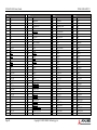
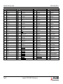
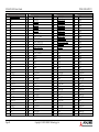
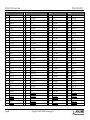
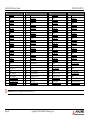
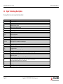
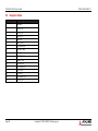
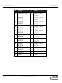
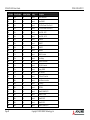
4. Pinout and Signal Descriptions .......................................................................................................................................................................................................................................................................... 21
4.1. Pin Summary .................................................................................................................................................................................................................................................................................................................................. 21
4.2. Signal Terminology Descriptions ........................................................................................................................................................................................................................................................................................... 28
4.3. Signal Descriptions on J1/J2 Connectors ............................................................................................................................................................................................................................................................................ 29
4.3.1 Ethernet KR ........................................................................................................................................................................................................................................................................................................................ 29
4.3.2 NBASE-T Ethernet ............................................................................................................................................................................................................................................................................................................ 31
4.3.3 PCI Express ......................................................................................................................................................................................................................................................................................................................... 33
4.3.4 USB ........................................................................................................................................................................................................................................................................................................................................ 40
4.3.5 SATA ..................................................................................................................................................................................................................................................................................................................................... 42
4.3.6 Asynchronous Serial Port .............................................................................................................................................................................................................................................................................................. 43
4.3.7 I2C ......................................................................................................................................................................................................................................................................................................................................... 43
4.3.8 eSPI ....................................................................................................................................................................................................................................................................................................................................... 44
4.3.9 Boot SPI (BIOS ONLY) and Boot Select .................................................................................................................................................................................................................................................................... 44
4.3.10 Port 80 Support on USB_PD I2C Bus ........................................................................................................................................................................................................................................................................ 45

COM-HPC-sIDH User’s Guide PICMG COM-HPC R1.1
Page 8 Copyright © 2023 ADLINK Technology, Inc.
4.3.11 IPMB ..................................................................................................................................................................................................................................................................................................................................... 46
4.3.12 General Purpose SPI ....................................................................................................................................................................................................................................................................................................... 46
4.3.13 Power & System Management ................................................................................................................................................................................................................................................................................... 47
4.3.14 Rapid Shutdown ............................................................................................................................................................................................................................................................................................................... 48
4.3.15 Thermal Protection .......................................................................................................................................................................................................................................................................................................... 48
4.3.16 SMBus .................................................................................................................................................................................................................................................................................................................................. 49
4.3.17 General Purpose Input Outputs .................................................................................................................................................................................................................................................................................. 49
4.3.18 Module Type Definition ................................................................................................................................................................................................................................................................................................. 50
4.3.19 Miscellaneous Signals .................................................................................................................................................................................................................................................................................................... 51
4.3.20 Power and Ground .......................................................................................................................................................................................................................................................................................................... 52
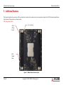
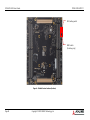
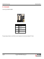
5. Additional Features ................................................................................................................................................................................................................................................................................................. 53
5.1 Debug Connector (40-pin connector) .................................................................................................................................................................................................................................................................................. 55
5.2 Status LEDs ..................................................................................................................................................................................................................................................................................................................................... 56
5.3 Exception Codes ........................................................................................................................................................................................................................................................................................................................... 57
5.4 Fan Connector ............................................................................................................................................................................................................................................................................................................................... 58
5.5 BIOS Default Reset ...................................................................................................................................................................................................................................................................................................................... 59
5.6 BIOS Boot Select .......................................................................................................................................................................................................................................................................................................................... 60
5.7 MIPI 60 Debug Header .............................................................................................................................................................................................................................................................................................................. 61
6. System Resources .................................................................................................................................................................................................................................................................................................... 63
6.1 System Memory Map ................................................................................................................................................................................................................................................................................................................. 63
6.2 I/O Map ........................................................................................................................................................................................................................................................................................................................................... 64
6.3 Interrupt Request (IRQ) Lines .................................................................................................................................................................................................................................................................................................. 65
6.4 PCI Configuration Space Map ................................................................................................................................................................................................................................................................................................. 66
6.5 PCI Interrupt Routing Map ....................................................................................................................................................................................................................................................................................................... 70
6.6 SMBus Address Table ................................................................................................................................................................................................................................................................................................................. 71
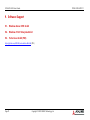
7. BIOS Setup .................................................................................................................................................................................................................................................................................................................. 72
7.1 Menu Structure ............................................................................................................................................................................................................................................................................................................................. 72
8. BIOS Checkpoints, Beep Codes .......................................................................................................................................................................................................................................................................... 74
9. Software Support ..................................................................................................................................................................................................................................................................................................... 75
9.1. Windows Server 2019 64-bit ................................................................................................................................................................................................................................................................................................... 75
9.2. Windows 10 IoT Enterprise 64-bit ......................................................................................................................................................................................................................................................................................... 75
9.3. Yocto Linux 64-bit (TBC) ............................................................................................................................................................................................................................................................................................................ 75
10. Mechanical .................................................................................................................................................................................................................................................................................................................. 76
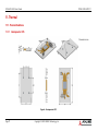
11. Thermal ........................................................................................................................................................................................................................................................................................................................ 77
11.1. Thermal Solutions ........................................................................................................................................................................................................................................................................................................................ 77

COM-HPC-sIDH User’s Guide PICMG COM-HPC R1.1
Page 9 Copyright © 2023 ADLINK Technology, Inc.
11.1.1 Heatspreader: HTS ........................................................................................................................................................................................................................................................................................................... 77
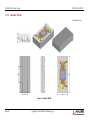
11.1.2 Heatsink: THS-BL .............................................................................................................................................................................................................................................................................................................. 78
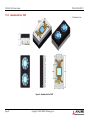
11.1.3 Heatsink with Fan: THSF ................................................................................................................................................................................................................................................................................................ 79
11.1.4 Heatsink with Fan: THSF-BL-S ..................................................................................................................................................................................................................................................................................... 80

COM-HPC-sIDH User’s Guide PICMG COM-HPC R1.1
Page 10 Copyright © 2023 ADLINK Technology, Inc.
List of Figures
Figure 1 – Module function diagram ...................................................................................................................................................................................................................................................................... 20
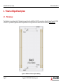
Figure 2 - Module rear side row and pin numbering ...................................................................................................................................................................................................................................... 21
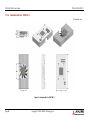
Figure 3 – Module feature locations (front) ......................................................................................................................................................................................................................................................... 53
Figure 4 – Module feature locations (bottom) ................................................................................................................................................................................................................................................... 54
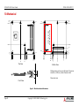
Figure 5 – Module mechanical dimensions ......................................................................................................................................................................................................................................................... 76
Figure 6 – Heatspreader: HTS .................................................................................................................................................................................................................................................................................... 77
Figure 7 – Heatsink: THS-BL ....................................................................................................................................................................................................................................................................................... 78
Figure 8 – Heatsink with Fan: THSF ......................................................................................................................................................................................................................................................................... 79
Figure 9 – Heatsink with Fan: THSF-BL-S .............................................................................................................................................................................................................................................................. 80

COM-HPC-sIDH User’s Guide PICMG COM-HPC R1.1
Page 11 Copyright © 2023 ADLINK Technology, Inc.
1. Introduction
The COM-HPC-sIDH is a Server Type COM-HPC Size D module based on Intel® Xeon® D-2700 processors (formerly “Ice Lake-D HCC”). The processor
puts an emphasis on longevity and industrial-class reliability, offers up to 20 cores at 3.1GHz boost frequency, and features AVX512-VNNI (Vector
Neural Network Instructions) that deliver accelerated AI inferencing performance. Typical industries in need of such high performance, low power
characteristics include industrial automation and control, medical ultra sound, image processing and analysis, high-speed video encoding and streaming,
predictive traffic analysis, and multi-camera-based AI.
The COM-HPC-sIDH has up to four DIMM sockets supporting up to 256GB (4x 64GB) of DDR4 RDIMM memory, or even higher with LRDIMM. It
provides a memory frequency of up to 3200 MT/s, dependent on system configuration.
Selected SKUs features industrial class reliability with extended temperature range operability. Combined with ultra-low latency-focused Intel® Time
Coordinated Computing (Intel® TCC) technology, COM-HPC-sIDH is well suited for mission critical, hard real-time, and rugged solutions.
The integrated high speed Ethernet controller inside Intel® Xeon® D-2700 processors provides up to 8x 10G networking with selected PHY on carrier
for SFP+ or 10GBASE-T feature, or 4x 25G based on selected PHY on carrier for SFP+, or 10G/25G in KR backplane usage and even up to 40G/50G/100G
(TBC) in KR backplane usage. It also includes an onboard 2.5Gigabit Ethernet port with optional Time Sensitive Network (TSN) support.
An optional IPMB via MMC (module management controller, located on module) and a dedicated PCIe lane (PCIe_BMC) are also offered. By connecting
these IPMB, dedicated PCIe lane and other management buses, such as eSPI, UART, to the carrier board BMC (for example, AST2500), it allows for out-
of-band management.
Inputs/outputs provided include up to two PCIe Gen4 x16 and another two PCIe Gen3 x8 lanes that can be used for AI accelerator and NVMe SSD, four
USB 3.0/2.0 ports, two SATA 6Gb/s ports, and 12x GPIO pins. TPM chip is equipped for security-related usage. Optional onboard eMMC is offered by
project basis. Support for SMBus, two I2C. is also available The module is equipped with SPI AMI EFI BIOS with CMOS backup, supporting embedded
features such as remote console, hardware monitor, and watchdog timer.

COM-HPC-sIDH User’s Guide PICMG COM-HPC R1.1
Page 12 Copyright © 2023 ADLINK Technology, Inc.
2. Specifications
2.1. Core System
CPU
Intel® Xeon® D-2700 Processor (formerly “Ice Lake-D HCC”)
• Intel® Xeon® D-2796TE, 2.0/3.1GHz, 30MB, 20C/40T, 118W (100G Ethernet bandwidth) (eTemp)
• Intel® Xeon® D-2775TE, 2.0/3.1GHz, 25MB, 16C/32T, 100W (100G Ethernet bandwidth) (eTemp)
• Intel® Xeon® D-2752TER, 1.8/2.8GHz, 20MB, 12C/24T, 77W (50G Ethernet bandwidth) (eTemp)
• Intel® Xeon® D-2733NT, 2.1/3.2GHz, 15MB, 8C/16T, 80W (50G Ethernet bandwidth) (Intel QAT)
• Intel® Xeon® D-2712T, 1.9/3.0GHz, 15MB, 4C/8T, 65W (50G Ethernet bandwidth)
Note: Other non-IOTG SKU not listed may be supported by project basis. Please contact our ADLINK local representative.
Memory
Up to 256GB (4x 64GB) DDR4 RDIMM in four DIMM sockets (up to 512 GB by 4x 128GB configuration at LRDIMM, TBC)
Up to 2933 MT/s for D-2796TE/D-2775TE, 2667 MT/s for D-2752TER/D-2733NT/D-2712T
1 DIMM per channel architecture for maximum performance
Embedded BIOS
AMI Aptio V UEFI with CMOS backup in 64 (or 32, TBC) MB SPI BIOS, dual BIOS by build option

COM-HPC-sIDH User’s Guide PICMG COM-HPC R1.1
Page 13 Copyright © 2023 ADLINK Technology, Inc.
2.2. Expansion Busses
1 PCI Express x16 Gen4: Lane 16-31 (configurable to 1 x16, 2 x8 or 4 x4)
1 PCI Express x16 Gen4: Lane 32-47 (configurable to 1 x16, 2 x8 or 4 x4)
1 PCI Express x8 Gen3: Lane 0-7 (configurable to 1 x8, 2 x4, 4 x2 or 4 x1. x1 usage at Lane 0, 2, 4, 6)
1 PCI Express x8 Gen3: Lane 8-15 (configurable to 1 x8, 2 x4, 4 x2 or 4 x1. x1 usage at Lane 8, 10, 12, 14)
Additional 1 PCI Express x1 Gen3 (PCIe_BMC) is used for connecting to carrier board BMC
Note: Gen4 support dependent on carrier design.
4 PCI Express Reference Clock:
PCIe_REFCLK0_LO: used for PCIe Lane 0-7 and PCIe_BMC recommended
PCIe_REFCLK0_HI: used for PCIe Lane 8-15 recommended
PCIe_REFCLK1: used for PCIe Lane 16-31 recommended
PCIe_REFCLK2: used for PCIe Lane 32-47 recommended
Note: PCIe 8-11 should be used for the first NVMe instance and PCIe 12-15 should be used for the second NMVe instance. These are
recommended by COM-HPC specifications.
Other: SMBus (system), 2x I2C (user, I2C_0, I2C_1, I2C_0 offers ALERT#), eSPI bus

COM-HPC-sIDH User’s Guide PICMG COM-HPC R1.1
Page 14 Copyright © 2023 ADLINK Technology, Inc.
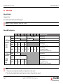
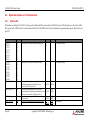
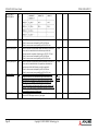
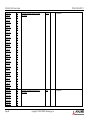
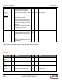
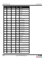
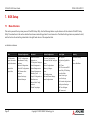
2.3. Ethernet KR
Ethernet Controller
Integrated on SoC
Up to 8x Ethernet KR interfaces with sideband signals
Note: PHY on carrier is required for Optical Fiber / Copper.
Ethernet MAC configuration
KR_0
KR_1
KR_2
KR_3
KR_4
KR_5
KR_6
KR_7
Note for possible usage
For 100G Ethernet
Bandwidth SKU
D-2796TE
D-2775TE
2x 100G
100G
100G (failover)
Backplane usage
2x 50G
50G
50G
Backplane usage
2x 40G
40G
40G
Backplane usage
4x 25G 25G 25G 25G 25G
Backplane usage
SFP+ (1pc, C827 on carrier)
8x 10G 10G 10G 10G 10G 10G 10G 10G 10G
Backplane usage
SFP+ (2pcs, C827 on carrier)
10G BASE-T (2pcs, X557-AT4 on carrier)
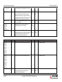
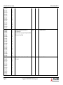
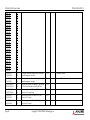
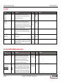
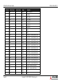
For 50G Ethernet
Bandwidth SKU
D-2752TER
D-2733NT
D-2712T
1x 50G 50G Backplane usage
1x 40G 40G Backplane usage
4x 10G 10G 10G 10G 10G
Backplane usage
SFP+ (1pc, C827 on carrier)
10G BASE-T (1pc, X557-AT4 on carrier)
Note:
1. Firmware for each configuration may differ and is dependent on silicon vendor.
2. Table above shows highest speed supported per lane and can be configured to lower speeds.

COM-HPC-sIDH User’s Guide PICMG COM-HPC R1.1
Page 15 Copyright © 2023 ADLINK Technology, Inc.
3. 10G and 40G support require the use of 4 lanes, while 50G support require 2 lanes.
4. For detailed circuit information between Ethernet Controller, PHY, and firmware, please contact your local ADLINK representative.
2.4. Ethernet NBASE-T
1x NBASE-T port
Onboard Intel® i225 series (IT version) Ethernet Controller
2.5Gbps, 1Gbps and 100/10Mbps connections, 1000BASE-T mode support
IT version supports TSN on Linux OS, with NBASET0_SDP available when TSN support is enabled (TBC)
2.5. Multi I/O and Storage
USB
4x USB3.0/2.0/1.1 (USB 0, 1, 2, 3)
SuperSpeed, High-Speed, Full-Speed and Low-Speed USB signaling
SATA (TBC)
2x SATA 6Gb/s (SATA 0, 1)
Note: HSIO combined bandwidth support can be up to the equivalence of 16 PCIe Gen3 lanes. PCIe lane 0-15, SATA, USB High-speed SSTX/RX
pair, NBASE-T, and PCIe_BMC are sourced from HSIO.

COM-HPC-sIDH User’s Guide PICMG COM-HPC R1.1
Page 16 Copyright © 2023 ADLINK Technology, Inc.
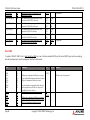
On-board Storage
eMMC 5.1, ranges from 32GB/64GB. Build option support by project basis
eMMC as boot-up device for Windows Server 2019 (Yocto support TBC)
GPIO
12x GPIO
GPI with interrupt
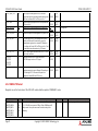
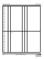
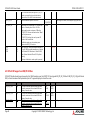
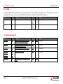
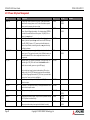
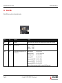
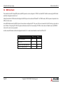
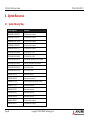
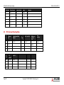
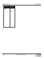
UART
2x UART interfaces on module
Console Redirection COM 1 or COM 2 selectable in BIOS
COM Port
Description
IRQ
Address
Console Redirection Support
COM 0
Supported by module (UART 0), via embedded controller
4
0x3F8
Yes
COM 1
Supported by module (UART 1), via embedded controller
5
0x2F8
Yes
Note:
1. The Carrier BMC of ADLINK’s reference COM-HPC Server Base offers 2x UART ports and share the physical connector/header with module’s
UART ports, which can be switched using jumper settings.
2. Carrier BMC_UART_0 and Module_UART_0 connect to a DB9 connector of COM-HPC Server Base. It can be used as BMC Serial over LAN if
sourced from Carrier BMC_UART_0. The Carrier BMC_UART_0 IRQ is 9, Address is 0x220.
3. Carrier BMC_UART_1 and Module_UART_1 connect to a pin header of COM-HPC Server Base. It can be used as console module. The Carrier
BMC_UART_1 IRQ is 10, Address is 0x228.

COM-HPC-sIDH User’s Guide PICMG COM-HPC R1.1
Page 17 Copyright © 2023 ADLINK Technology, Inc.
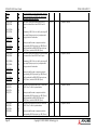
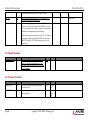
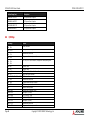
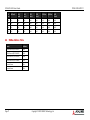
2.6. Trusted Platform Module (TPM)
Chipset: Infineon solution
Type: TPM 2.0 (SPI bus based)
2.7. SEMA Board controller
Supports: Voltage/current monitoring, power sequence debug support, logistics and forensic information, general purpose I2C, failsafe BIOS (dual BIOS,
build opt. support), watchdog timer and fan control
2.8. Remote Management & Module Management Controller (MMC)
An IPMB (Intelligent Platform Management Bus) port and PCIe_BMC lane can work in conjunction with Carrier BMC for remote management
applications, build option, supported by project basis
IPMB
It is offered by MMC (Module Management Controller) and is used for the connection between Carrier BMC and module MMC, build option
PCIe_BMC
It is a dedicated PCIe x1 lane for Carrier BMC, lets Carrier BMC emulate graphics card features and is mainly used for KVM
MMC, Module Management Controller
It works in conjunction with Carrier BMC through IPMB and/or UART, I2C
Reacts with Carrier BMC, e.g. forwarding COM-HPC module’s temperature, voltage, FAN speed, board information to Carrier BMC.

COM-HPC-sIDH User’s Guide PICMG COM-HPC R1.1
Page 18 Copyright © 2023 ADLINK Technology, Inc.
Information is either obtained by MMC itself through GPIO/I2C or by communication with SEMA Board Controller. Remotely power on/off COM-HPC
module through Carrier BMC/MMC is also supported
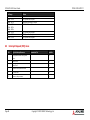
2.9. Debug
40-pin flat cable connector for use with DB40-HPC debug module
Supports BIOS POST code LED, SEMA Board Controller access, Module Management Controller access, SPI BIOS flashing, internal power rail test points,
debug LEDs
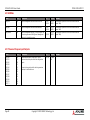
2.10. Power
Power Modes: AT mode
Standard Voltage Input: AT: 12V±5%Power Management: ACPI 5.0 compliant
Power States: S0, S5 (WoL S5)
2.11. Mechanical and Environmental
Form Factor and Specification
PICMG COM-HPC Rev 1.1, Server Type, Size D 160 x 160 mm
Operating Temperature
Standard 0°C to 60°C (Standard Voltage Input) Storage: -20°C to 80°C
Extreme Rugged -40°C to 85°C (Standard Voltage Input) Storage: -40°C to 85°C
(Selected SoC SKUs)

COM-HPC-sIDH User’s Guide PICMG COM-HPC R1.1
Page 19 Copyright © 2023 ADLINK Technology, Inc.
Humidity
5-90% RH operating, non-condensing, 5-95% RH storage (and operating with conformal coating)
Shock and Vibration
IEC 60068-2-64 and IEC-60068-2-27
MIL-STD-202F, Method 213B, Table 213-I, Condition A and Method 214A, Table 214-I, Condition D
HALT tested
Thermal Stress, Vibration Stress, Thermal Shock and Combined Test

COM-HPC-sIDH User’s Guide PICMG COM-HPC R1.1
Page 20 Copyright © 2023 ADLINK Technology, Inc.
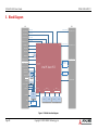
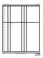
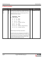
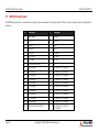
3. Block Diagram
Figure 1 – Module function diagram
BIOS
BIOS
PCIe Lane 16-31
PCIe Lane 32-47
PCIe Lane 48-63
ETH_Sidebands
Intel® Xeon® D
Gen4
1 x4, 2 x2
1 x4, 2 x2
1 x16, 2 x8, 4 x4
DIMM
J1 J2
LAN
I225
eSPI
TPM
1 x16, 2 x8, 4 x4
DIMM
iMC 0
Ch0Ch1
iMC 1
Ch3Ch4
DIMM DIMM
eMMC 5.1
32/64GB
Max. 2.5G
SMB
XDP
debug connector
EEPROM (FRU)
HSUART
SEMA
Board
Controller
1 x4, 2 x2
1 x4, 2 x2
MMC
Gen4
1x SSTX/SSRX
pair per port
PCIe Lane 0-3
PCIe Lane 4-7
PCIe Lane 8-11
PCIe Lane 12-15
PCIe_BMC x1
ETH_KR 0-3
ETH_KR 4-7
NBASE-T 0
USB 2.0 Lane 0-3
USB 2.0 Lane 4-7
USB 3.x Lane 0-3
USB_PD_I2C/ALERT#
SATA Port 1
SATA Port 0
BOOT_SPI
GPP_SPI
SMBus
I2C 0
(w/ ALERT#)
I2C 1
UART 0-1
12x GPIO
IPMB
eSPI
Page is loading ...
Page is loading ...
Page is loading ...
Page is loading ...
Page is loading ...
Page is loading ...
Page is loading ...
Page is loading ...
Page is loading ...
Page is loading ...
Page is loading ...
Page is loading ...
Page is loading ...
Page is loading ...
Page is loading ...
Page is loading ...
Page is loading ...
Page is loading ...
Page is loading ...
Page is loading ...
Page is loading ...
Page is loading ...
Page is loading ...
Page is loading ...
Page is loading ...
Page is loading ...
Page is loading ...
Page is loading ...
Page is loading ...
Page is loading ...
Page is loading ...
Page is loading ...
Page is loading ...
Page is loading ...
Page is loading ...
Page is loading ...
Page is loading ...
Page is loading ...
Page is loading ...
Page is loading ...
Page is loading ...
Page is loading ...
Page is loading ...
Page is loading ...
Page is loading ...
Page is loading ...
Page is loading ...
Page is loading ...
Page is loading ...
Page is loading ...
Page is loading ...
Page is loading ...
Page is loading ...
Page is loading ...
Page is loading ...
Page is loading ...
Page is loading ...
Page is loading ...
Page is loading ...
Page is loading ...
-
 1
1
-
 2
2
-
 3
3
-
 4
4
-
 5
5
-
 6
6
-
 7
7
-
 8
8
-
 9
9
-
 10
10
-
 11
11
-
 12
12
-
 13
13
-
 14
14
-
 15
15
-
 16
16
-
 17
17
-
 18
18
-
 19
19
-
 20
20
-
 21
21
-
 22
22
-
 23
23
-
 24
24
-
 25
25
-
 26
26
-
 27
27
-
 28
28
-
 29
29
-
 30
30
-
 31
31
-
 32
32
-
 33
33
-
 34
34
-
 35
35
-
 36
36
-
 37
37
-
 38
38
-
 39
39
-
 40
40
-
 41
41
-
 42
42
-
 43
43
-
 44
44
-
 45
45
-
 46
46
-
 47
47
-
 48
48
-
 49
49
-
 50
50
-
 51
51
-
 52
52
-
 53
53
-
 54
54
-
 55
55
-
 56
56
-
 57
57
-
 58
58
-
 59
59
-
 60
60
-
 61
61
-
 62
62
-
 63
63
-
 64
64
-
 65
65
-
 66
66
-
 67
67
-
 68
68
-
 69
69
-
 70
70
-
 71
71
-
 72
72
-
 73
73
-
 74
74
-
 75
75
-
 76
76
-
 77
77
-
 78
78
-
 79
79
-
 80
80


Ask a question and I''ll find the answer in the document
Finding information in a document is now easier with AI