Novus N321 Temperature Controllers User manual
- Category
- Measuring, testing & control
- Type
- User manual

NOVUS AUTOMATION 1/6
N
321, N322, N323
TEMPERATURE CONTROLLERS
– USER GUIDE – V1.8x
1. SAFETY ALERTS
The symbols below are used in the device and throughout this
manual to draw the user’s attention to valuable information related to
device safety and use.
CAUTION:
Read the manual fully before
installing and operating the device.
CAUTION OR HAZARD:
Risk of electric shock.
All safety recommendations appearing in this manual must be
followed to ensure personal safety and prevent damage to the
instrument or system. If the instrument is used in a manner other
than that specified in this manual, the device’s safety protections may
not be effective.
2. SUMMARY
1. SAFETY ALERTS ........................................................................ 1
2. SUMMARY .................................................................................. 1
3. INTRODUCTION ......................................................................... 1
4. SPECIFICATIONS ....................................................................... 1
5. ELECTRICAL CONNECTIONS ................................................... 2
5.1 N321 MODEL ....................................................................... 2
5.2 N322 MODEL ....................................................................... 2
5.3 N323 MODEL ....................................................................... 3
5.4 INSTALLATION RECOMMENDATIONS .............................. 3
6. OPERATION................................................................................ 3
6.1 LEVEL 1 – SETPOINT ADJUSTMENT LEVEL .................... 3
6.2 LEVEL 2 – OPERATION MODE LEVEL .............................. 3
6.3 LEVEL 3 – CALIBRATION LEVEL ....................................... 4
7. OPERATION................................................................................ 5
7.1 N321 MODEL: OPERATION ................................................ 5
7.2 N322 AND N323 MODELS: OPERATION ........................... 5
7.3 N322 AND N323 MODELS: ALARM FUNCTIONS .............. 5
7.4 N323 MODEL: ALARM TIMER ............................................. 5
8. CONFIGURATION PROTECTION .............................................. 5
8.1 CONFIGURATION PROTECTION OPERATION................. 6
9. MASTER PASSWORD ................................................................ 6
9.1 HOW TO USE YOUR MASTER PASSWORD ..................... 6
10. ERROR INDICATION .................................................................. 6
11. SERIAL COMMUNICATION ........................................................ 6
11.1 FEATURES ........................................................................... 6
11.2 PARAMETER CONFIGURATION ........................................ 6
11.3 COMMUNICATION PROTOCOL ......................................... 6
11.4 REGISTER TABLE ............................................................... 6
12. WARRANTY ................................................................................ 6
3. INTRODUCTION
N321, N322, and N323 are temperature controllers for heating and
cooling. They are distinguished by the number of outputs available:
• N321: It has 1 output channel: OUT1.
• N322: It has 2 output channels: OUT1 and OUT2.
• N323: It has 3 output channels: OUT1, OUT2, and OUT3.
The models are subdivided by the type of temperature sensor
supported:
• NTC: Model accepting only the NTC sensor.
• Pt100: Model accepting only the Pt100 sensor.
• J/K/T: Model accepting only J, K and T sensors.
The features of each controller are in accordance with the purchase
order and are shown on the label attached to the body of the
controller itself.
Example of the label of an N323 model:
Figure 1 – Identification label
These models may have differences in power supply and the
availability of an RS485 communication channel.
4. SPECIFICATIONS
Sensor Input: The choice of sensor is made at the time of purchase
and shown on the controller identification label. There are three
options:
NTC Input:
Type: .......... NTC Thermistor, R25 = 10 kΩ, 1%, β25/85 = 3435 K 1 %
Measurement range: ............................... -50 to 120 °C / -58 to 248 °F
Measurement accuracy: .......................................... ± 1 °C @ 25 °C
Pt100 Input:
Type: ............................................................................. Pt100, α = 385
Measurement range: ............................... -50 to 300 °C / -58 to 572 °F
Measurement accuracy: ........................ 0.2 % F.S. ± 2 °C @ 25 °C
J/K/T Input:
Measurement range J: ................................ 0 to 600 °C / 32 to 999 °F
Measurement range K: ............................. -50 to 999 °C / 32 to 999 °F
Measurement range T: ............................. -50 to 400 °C / 32 to 752 °F

N321, N322, N323
NOVUS AUTOMATION 2/6
Measurement accuracy: ......................... 0.2 % F.S. ± 2 °C @ 25 °C
Notes:
1. All input types are factory calibrated.
2. The thermocouples follow the NBR 12771/99 standard.
3. The Pt100 follow the NBR 13773/97 standard.
4. The operating range of the NTC sensor cable, which may come
with the controller, is limited to -30 to +105 °C. Its typical length
is 3 meters. It can be extended up to 100 meters. It is composed
of two wires of 0.5 mm² section.
Measurement resolution: .............. 0.1° in the range -19.9 to 199.9°
..................................................................... 1° in the rest of the range
OUT1: ................................................................................ SPDT relay
........................................ 1 HP 250 Vac / 1/3 HP 125 Vac (16 A Res.)
OUT2: ................................................ Relay: 3 A / 250 Vac, SPST-NO
OUT3: ................................................ Relay: 3 A / 250 Vac, SPST-NO
Power supply:
Voltage: ................................... 100 to 240 Vac/dc (± 10 %)
Frequency: ........................................................... 50~60 Hz
Consumption: ............................................................... 5 VA
Optionally: .......................................... 24 V (12~30 Vdc/ac)
Dimensions:
Width x height x depth: .............................. 75 x 33 x 75 mm
Panel cut-out: .................................................... 70 x 29 mm
Weight: ...................................................................... 100 g
Operation conditions:
Operation temperature: ....................................... 0 to 40 °C
Storage temperature: ....................................... -20 to 60 °C
Relative humidity: ......................................... 20 to 85 % RH
Connections for wires up to 4.0 mm².
Housing: Polycarbonate UL94 V-2.
Protection degree: Enclosure IP42, front IP65.
RS485 interface (optional) with Modbus
protocol. Not electrically isolated from the input
circuit. Electrically isolated from the power
supply circuit.
5. ELECTRICAL CONNECTIONS
5.1 N321 MODEL
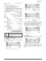
The figures below show the connection terminals for the N321
sensor, power supply, and output:
Figure 2 – Connections (NTC)
Figure 3 – Connections (Pt100 3-wire)
Figure 4 – Connections (Pt100 2-wire)
For Pt100, you must use a 3-wire Pt100 sensor, as shown in Figure
3. To use a 2-wire Pt100, use the connections shown in Figure 4. In
it, terminals 11 and 13 of the controller are interconnected.
To compensate the Pt100 sensor cables properly, the conductors
must all have the same electrical resistance (cross-section).
Figure 5 – Connections (Thermocouple)
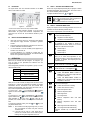
5.2 N322 MODEL
The figures below show the connection terminals for the N322
sensor, power supply, and output:
Figure 6 – Connections
* The serial communication feature is not always available in N322.
Pt100 3-wire. For 2-wire connection, terminals 11 and 13 must be
interconnected. For proper cable resistance compensation, the
conductors must all have the same electrical resistance (cross-
section).

N321, N322, N323
NOVUS AUTOMATION 3/6
5.3 N323 MODEL
The figures below show the connection terminals for the N323
sensor, power supply, and output:
Figure 7 – Connections
* The serial communication feature is not always available in N323.
Pt100 3-wire. For 2-wire connection, terminals 11 and 13 must be
interconnected. For proper cable resistance compensation, the
conductors must all have the same electrical resistance (cross-
section).
5.4 INSTALLATION RECOMMENDATIONS
• Input signal conductors should run through the plant separate
from output and supply conductors. If possible, in grounded
conduits.
• The power supply for the electronic instruments must come from
a network dedicated to the instrumentation.
• It is recommended to use RC FILTERS (noise suppressor) in
contactor coils, solenoids, etc.
• In control applications, it is essential to consider what can
happen when any part of the system fails. The controller internal
devices do not guarantee full protection.
6. OPERATION
Before use, the controller must be configured. To configure it, you
must set values for the parameters that determine how the
equipment operates.
These configuration parameters are organized in groups or Levels,
called Parameter Levels.
LEVEL
RELATED FUNCTIONS
0
Temperature measurement
1
Setpoint adjustment
2 Operation mode
3 Calibration
Table 1 – Parameter levels
When you turn on the controller, the display shows the version of the
equipment for 1 second. This information is important for eventual
consultations with the manufacturer. Then, the controller starts
presenting the temperature value measured by the sensor. This is
level 0 or the Temperature Measurement level.
To access level 1, press for 1 second until SP1 parameter
appears. To return to the temperature measurement level, press
again.
To access level 2, press for 2 seconds until VNT parameter
appears. Release the key to remain at this level. To access the
other parameters of this level, press again. After the last
parameter, the controller returns to the temperature measurement
level.
To change the parameter values, press the and keys until
you get the desired values.
Notes: 1 The controller saves the programming when you move
from one parameter to another. Only then will it be
considered valid.
2 If the keys are not used for a time longer than 20
seconds, the controller returns to the measuring level,
finishing and saving the configuration done so far.
6.1 LEVEL 1 – SETPOINT ADJUSTMENT LEVEL
At this level, only the Setpoint parameter (SP) is displayed. It defines
the desired temperature value for the system. The current value of
SP is shown alternately with the parameter.
To program the desired value, use and keys.
SP1
SP2
SP3
Setpoint
Setpoint values for the action of outputs 1, 2 and 3.
These values are limited to the values programmed in
SPL
and
SPk
in the Operation Mode cycle.
The available parameters are according to the model.
6.2 LEVEL 2 – OPERATION MODE LEVEL
Displays the sequence of the remaining parameters to be set. The
parameters are shown alternately with their values.
The number of outputs depends on the controller model.
vnt
Unit
Temperature unit. It allows you to choose the display
unit of the measured temperature.
0
Temperature in Celsius degrees.
1
Temperature in Fahrenheit degrees.
typ
Type
Type of temperature sensor to be used.
This parameter is only available in models for
THERMOCOUPLE sensors, where you can choose
between the J, K, and T thermocouples.
0
Thermocouple J
1
Thermocouple K
2
Thermocouple T
ofs
Offset
Correction value for temperature indication.
Allows you to make small adjustments to the
temperature indication to correct measurement errors
that appear, for example, when replacing the NTC
temperature sensor.
spl
SP Low Limit
Setpoint lower limit.
Must be defined with a value lower than
spK
.
spK
SP High Limit
Setpoint upper limit.
Must be defined with a value higher than
spl
.
A(1
Action 1
Output 1 action type:
0
Control with Reverse Action. Suitable for
heating. Turns on the control output when the
temperature is below SP.
1
Control with Direct Action
. Suitable for
cooling. Turns on the control output when the
temperature is above SP.
A(2
Action 2
A(3
Action 3
Output 2 and 3 action type:
0
Control. Reverse action for heating.
1
Control. Direct action for cooling.
2
Minimum temperature alarm.
3
Maximum temperature alarm.
4
Within-range alarm.
5
Out-of-range alarm.
6
Minimum temperature alarm with initial
blocking.
7
Maximum temperature alarm with initial
blocking.
8
Within-range alarm with initial blocking.
9
Out-of-range alarm with initial blocking.
Parameters available only for N322 and N323
models.

N321, N322, N323
NOVUS AUTOMATION 4/6
(nt
Control
Inversion between Setpoints and Outputs:
0
SP1 acts on OUTPUT 1 relay and SP2 acts on
OUTPUT 2 relay. Factory setting.
1
SP1 acts on OUTPUT 2 relay and SP2 acts on
OUTPUT 1 relay.
Parameter available only for the N322 and N323
models.
Ky1
Ky2
Ky3
Hysteresis
Control hysteresis. Parameter that applies to both
control and alarm.
Differential between the on and off point of the relay
output configured as a control output. In degrees.
dli
dl2
dl3
Delay
Delay time for both control start and alarm.
After the controller is turned on, the output (1, 2, or 3)
will only be turned on after the time programmed in
this parameter has elapsed.
Used in large refrigeration systems to prevent the
simultaneous activation of compressors when
returning of a power failure.
Value in seconds (from 0 to 250 seconds).
Parameters available only for N322 and N323
models.
of1
of2
of3
Off time
N321 Model:
Sets minimum off time for the output.
N322 and N323 Model:
Sets minimum off time for output 1 and, when in
Control Mode (Reverse Action and Direct Action), for
outputs 2 and 3.
In either model, when turned off, the output will stay
in this condition for at least the time programmed in
this parameter.
Typically used to increase the lifespan
of the
compressor in a refrigeration system. For heating
applications, program zero.
Not valid for thermocouples.
Value in seconds (0 to 999 seconds).
on1
on2
on3
on time
N321 Model:
Sets minimum on time for the output.
N322 and N323 Model:
Sets minimum on time for output 1 and, when in
Control Mode (Reverse Action and Direct Action), for
outputs 2 and 3.
In either model, when turned on, the output will stay
in this condition for at least the time programmed in
this parameter.
Typically used to increase the lifespan of the
compressor in a refrigeration system. For heating
applications, program zero.
Not valid for thermocouples.
Value in seconds (0 to 999 seconds).
2t1
2t2
Timer T1
Time interval T1 for alarm timing.
Defines the timed action of alarms, as shown in
Table 2.
Adjustable between 0 and 1999 seconds.
Parameter available when outputs 2 and 3 are
configured as alarms.
Parameters available only for the N323 model.
3t1
3t2
Timer T2
Time interval T2 for alarm timing.
Defines the timed action of alarms, as shown in
Table 2.
Adjustable between 0 and 1999 seconds.
Parameter available when outputs 2 and 3 are
configured as alarms.
Parameters available only for the N323 model.
Adr
Address
The controller with an RS485 serial communication
interface features the
Adr
parameter at the
Operation Mode level.
In this parameter, you define a communication
address for each network element. The address set
must be between 1 and 247.
6.3 LEVEL 3 – CALIBRATION LEVEL
The controller leaves the factory already calibrated. When a
recalibration is necessary, it must be performed by a specialized
professional. To access this level, press the key for more than 3
seconds.
If you access it by accident, do not press the and keys.
Using the key, simply step through all the parameters, until the
controller returns to the measurement screen.
pas
Password. Parameter to enter a password that will
allow you to change the other parameters.
[Al
Calibration low.
Allows to set the Offset of the
measurement range. Adjusts the lower value of the
sensor measurement range.
[Ak
Calibration high. A
llows to calibrate the measure
scale gain. Adjusts the upper value of the sensor
measurement range.
[jL
Cold Junction calibration. Allows to calibrate the Cold
Junction Offset.
Only available for thermocouples.
FA(
Factory calibration. Allows to return to the controller
original calibration.
When changing from
0
to
1
, the original calibration
will be restored, and the changes made during the
calibration will be discarded.
Prt
Protection. Allows to define the parameter levels to
be protected.
Pa(
Password change.
Allows to change the current
password. You can set the password to a number
between 1 and 999.
Sn2
Serial number 2. Displays the first two digits of the
electronic serial number of the controller.
sn1
Serial number 1. Displays the middle three digits of
electronic serial number of the controller.
sn0
Serial number 0. Displays the last three digits of the
electronic serial number of the controller.

N321, N322, N323
NOVUS AUTOMATION 5/6
7. OPERATION
7.1 N321 MODEL: OPERATION
The controller with a single output triggers this control output to bring
the process temperature to the value set in parameter SP1 (Setpoint
1).
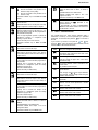
On the N323 front panel, the P1 flag will light when the control output
is turned on.
Figure 8 – Front panel
7.2 N322 AND N323 MODELS: OPERATION
Controller models with multiple outputs have typical applications in
alarm control and multi-stage power control.
In the alarmed control application, output 1 is used as the
temperature control output, while outputs 2 and 3 are programmed to
act as protection alarms or signaling.
In the multi-stage control application, the Setpoints of outputs 1, 2, and
3 are programmed to act at different temperatures. This allows you to
trigger the compressors in a progressive sequence, increasing the
refrigeration capacity as the temperature rises and reducing it when the
temperature approaches the temperature programmed for SP1.
By using the compressor delay (dL1, dL2, and dL3), you ensure
that, when returning from a power failure or when starting the
system, the compressors will start according to the programmed
timing. This allows you to reduce the energy demand.
Another typical application for the use of a multi-output controller
concerns the automatic changeover of the hot/cold cycle, where
one output will be programmed with Reverse Action and will
command heating, and another will be programmed with Direct
Action and will command cooling.
7.3 N322 AND N323 MODELS: ALARM FUNCTIONS
The N322 and N323 models have 8 alarm functions for outputs 2 and
3. A(2 and A(3 parameters can be programmed with the following
values:
2
Minimum temperature alarm: The output turns on when
the measured temperature is below the value programmed
in the corresponding Setpoint (
SP2
or
SP3
).
3
Maximum temperature alarm: The output turns on when
the measured temperature is above the value programmed
in the corresponding Setpoint (
SP2
or
SP3
).
4
Within range temperature alarm: The output turns on
when the measured temperature is within the temperature
range defined by:
(
SP1
–
SP2
) and (
SP1
+
SP2
) or
(
SP1
–
SP3
) and (
SP1
+
SP3
)
5
Out-of-range temperature alarm:
The output turns on
when the measured temperature is outside the
temperature range defined by:
(SP1 – SP2)
and
(SP1 + SP2)
or
(
SP1
–
SP3
) and (
SP1
+
SP3
)
Functions 6, 7, 8, and 9 are identical to the functions mentioned in
this section, but they have the Initial Alarm Blocking feature, which
blocks the alarm (does not allow it to activate) when the controller
initiates control already in an alarm condition.
The alarm will be unblocked after the equipment goes through a non-
alarm condition.
Although they have the same operation and alarm
functions, the N322 and N323 models
have a
different number of outputs (2 outputs for the former;
3 outputs for the latter), which should be considered
while reading the above explanation.
Therefore, the N322 model will not show the
dL3
and
SP3
parameters, for example. Other differences
may exist.
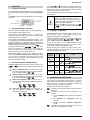
7.4 N323 MODEL: ALARM TIMER
The N323 model allows you to program a timer for alarms. You can
set 3 conditions: 1) delay on alarm triggering, 2) pulse when
triggering, or 3) triggering as sequential pulses.
Timing is only available for outputs 2 and 3 and can be programmed
using the following parameters: 2t1, 3t1, 2t2, and 3t2. The
figures in Table 2 represent these functions.
T1 and T2 can range from 0 to 1999 seconds, and their
combinations determine the timing mode. For the alarms to have
normal operation, without timings, program 0 (zero).
P2 and P3 flags light up whenever an alarm condition occurs,
regardless of the status of the output relays. During the delay, the
respective signal flag remains blinking.
ALARM
OUTPUT
FUNCTION
T1 T2 ACTION
Normal
Operation 0 0
Delay 0 1 a
1999 s
Pulse 1 a
1999 s 0
Oscillator 1 a
1999 s
1 a
1999 s
Table 2 – Timer functions for alarms 1 and 2
8. CONFIGURATION PROTECTION
The purpose of the configuration protection system is to prevent
undue changes to the parameters and, consequently, to its operating
mode. This system is composed of parameters that define the
protection degree to be adopted: Total or partial.
Parameters that define the level of protection:
Pas Parameter to enter a password to allow changes to the other
parameters.
Prt Parameter to define the levels of parameters to be
protected.
1. Only the Calibration level is protected (factory setting
option).
2. The Calibration and Configuration levels are
protected.
3. All levels are protected: Calibration, Configuration,
and SP.
PA( Parameter to change the current password. You can set the
password to a number between 1 and 999.
Alarm Event
Alarm
Output
Alarm Event
Alarm
Output
T2
Alarm Event
Alarm
Output
T1
Alarm Event
Alarm
Output
T1
T2
T1

N321, N322, N323
NOVUS AUTOMATION 6/6
8.1 CONFIGURATION PROTECTION OPERATION
The PAS parameter appears at the beginning of the protected level.
If you enter the password correctly, you can change the parameters
of the protected levels. If you do not enter the password correctly or
simply pass by this parameter, the parameters of the protected levels
can only be viewed and not changed.
Important notes:
1. When you enter an incorrect password five consecutive times,
the equipment will prevent new attempts for 10 minutes. If you
do not remember the current password, you can enter a master
password, which only allows you to set a new password.
2. The equipment leaves the factory with password 111.
9. MASTER PASSWORD
The master password, which allows you to set a new password for
the controller, uses the serial number of the equipment. It is
composed as follows:
[ 1 ] + [ largest number of SN2 ] + [ largest number of SN1 ] + [
largest number of SN0 ]
The master password for an equipment with serial number 97123465
is: 1936
Example: 1 + sn2 = 97; sn1 = 123; sn0 = 465 = 1 + 9 + 3 + 6
9.1 HOW TO USE YOUR MASTER PASSWORD
1. In the Pas parameter, enter the master password.
2. In the PA( parameter, enter any new non-zero (0) password.
3. Use the new password.
10. ERROR INDICATION
On the display, the controller shows messages that correspond to
problems related to temperature measurement. Whenever they are
displayed, the control output relay will be turned off immediately.
• The temperature has exceeded the upper limit of
the sensor range.
• Pt100 or T/C sensor broken. NTC sensor short-
circuited.
• The temperature has exceeded the lower
limit of
the sensor range.
• Pt100 or T/C sensor short-circuited. Broken NTC
sensor.
Table 3 – Error indications
11. SERIAL COMMUNICATION
The controller can optionally be supplied with an RS485 serial
communication interface, asynchronous, for communication with a
supervisor software.
11.1 FEATURES
• Signals compatible with RS485 standard.
• 2-wire connection between 1 master and up to 31 slave
controllers in bus topology. When using multi-output converters,
you can reach up to 247 nodes.
• Maximum connection distance: 1000 meters.
• Rate: 9600 bps
• Data bits: 8
• Parity: None
• Stop bits: 1
The RS485 signals are:
D1
D
D +
B
Bidirectional data line.
D0
D -
A Inverted bidirectional data line.
C
Optional connection that improves
communication performance.
GND
Table 4 – RS485
11.2 PARAMETER CONFIGURATION
To use serial communication, you must set the following parameter:
addr: Controller communication address.
11.3 COMMUNICATION PROTOCOL
The equipment supports the slave MODBUS RTU protocol, available
in most supervision software on the market.
The Modbus commands available are the following:
03 – Read Holding Register
06 – Preset Single Register
Command 03 (Read Holding Register) reads up to 4 consecutive
registers.
11.4 REGISTER TABLE
The following are the most used registers. For complete information,
refer to the Register Table for Serial Communication, available for
download in the product page.
ADDRESS PARAMETER REGISTER DESCRIPTION
0000 SP active Read: Setpoint da OUTPUT1.
Write: Setpoint da OUTPUT1.
Range: From
spll
to the value set in
spkl
.
0001 PV Read: Measured temperature variable.
Write: Not allowed.
Range: Equals the range of the sensor
used by the equipment.
Table 5 – Register table
12. WARRANTY
Warranty conditions are available on our website
www.novusautomation.com/warranty.
-
 1
1
-
 2
2
-
 3
3
-
 4
4
-
 5
5
-
 6
6


Novus N321 Temperature Controllers User manual
- Category
- Measuring, testing & control
- Type
- User manual
Ask a question and I''ll find the answer in the document
Finding information in a document is now easier with AI