Page is loading ...


LiveU Xtender User Guide
2
About This Guide
This user guide describes how to use the LiveU Xtender to increase network
reception of the LiveU Live Video Uplink units to which it is connected. The
LiveU Xtender can be used with the LU70 or LU40 units.
• Chapter 1, Introducing the LiveU Xtender, page 7, introduces the
LiveU Xtender, describes the contents of its suitcase and describes the
LiveU Xtender components.
• Chapter 2, LiveU Xtender Getting Started, page 13, describes how to
set up and get started using the LiveU Xtender.
• Appendix A, Limitation of Liability and Warranty, page 29, provides
the limitations on liability and warranty.
• Appendix B, FCC Compliance Statement, page 31, provides the FCC
compliance information.
Intended Audience
This user guide is intended to be used by operators of the LiveU Live Video
Uplink LU40 and LU70. The user guide assumes that operators are familiar
with any video equipment or infrastructure to which these LU units are
connected.
Additional Documentation
• LiveU LU70 and LU40 User Guide: Each user guide describes an LU live video uplink
unit. These user guides instruct camera operators about how to use the LU unit to
broadcast live streaming video.
• LiveU LU-1000 Studio Server User Guide: Describes how to use the LU-1000 live
video server software, which enables you to receive, view and configure high-quality live
video transmitted from LU70 units in the field.
• LiveU LU2000 Server (MMH) User Manual: Describes how to use the LiveU LU2000,
which provides multiple Multi-Media Hubs (MMHs) that enable you to receive, view and
configure high-quality live video transmitted from LU units in the field.
• LiveU Center User Guide: Describes how to remotely manage and control LU units and
MMHs on an LU2000 server through a standard Internet browser.

Table of Contents
3
Table of Contents
About This Guide ......................................................................................................... 1
Intended Audience ................................................................................................. 2
Additional Documentation .................................................................................... 2
Table of Figures ........................................................................................................... 4
Support and Contacting Information ....................................................................... 5
Chapter 1: Introducing the LiveU Xtender ............................................................... 7
Introduction ...................................................................................................................... 7
LiveU Xtender System Architecture ...................................................................... 8
What’s in the Suitcase? .................................................................................................. 9
LiveU Xtender Components ........................................................................................ 10
Status LEDs ...................................................................................................................... 12
Chapter 2: LiveU Xtender Getting Started ............................................................. 13
Workflow Overview ....................................................................................................... 13
Step 1, Installing the Hardware ................................................................................... 14
Vehicle Rooftop Installation ................................................................................. 14
Tripod Installation ................................................................................................... 17
Step 2, Connecting the LiveU Xtender to the LU Device ...................................... 18
LAN Connection ..................................................................................................... 18
USB Connection...................................................................................................... 19
Wi-Fi Connection .................................................................................................... 20
Step 3, Connecting the Power Source...................................................................... 23
Step 4, Turning On the LiveU Xtender ........................................................................ 24
Turning Off the LiveU Xtender .............................................................................. 24
Step 5, Configuring the LiveU Xtender Connection Type ...................................... 25
Step 6, Verifying the Connection ............................................................................... 26
Appendix A: Limitation of Liability and Warranty ................................................. 29
Limitation of Liability and Warranty ........................................................................... 29
Appendix B: FCC Compliance Statement ............................................................. 31

LiveU Xtender User Guide
4
Table of Figures
Figure 1: LiveU Xtender .......................................................................................................... 7
Figure 2: LiveU LU and Xtender Architecture .................................................................... 8
Figure 3: LiveU Tripod Xtender ............................................................................................ 10
Figure 4: LiveU Rooftop Xtender ........................................................................................ 10
Figure 5: SIM Card Slots ....................................................................................................... 11
Figure 6: Status LEDs ............................................................................................................. 12
Figure 7: Workflow – Setting Up the LiveU Xtender ......................................................... 13
Figure 8: Positioning LiveU Xtender on a Vehicle Rooftop............................................ 14
Figure 9: Positioning LiveU Xtender on a Vehicle Rooftop – Cable Connections .... 15
Figure 10: LiveU Xtender Space Requirements – Bottom Side ..................................... 15
Figure 11: Three Shark Fin Antennas .................................................................................. 15
Figure 12: Distance Between Antennas ........................................................................... 16
Figure 13: Mounting the Three Directional Antennas .................................................... 17
Figure 14: LiveU Xtender LAN (Ethernet) Port .................................................................. 18
Figure 15: LU40 and LU70 LAN (Ethernet) Ports ............................................................... 18
Figure 16: LiveU Xtender USB Port ...................................................................................... 19
Figure 17: LU70 USB Ports ..................................................................................................... 19
Figure 18: LiveU Xtender to Wi-Fi Access Point Connection ......................................... 20
Figure 19: LU70/LU40 Connectivity .................................................................................... 21
Figure 20: Wi-Fi Client Belt ................................................................................................... 22
Figure 21: Wi-Fi Client-to-LU70 USB Power Cable ............................................................ 24
Figure 22: Xtender Interface Settings Window ................................................................ 25
Figure 23: xTender WiFi Link ................................................................................................. 26
Figure 24: Remote Antenna Wi-Fi ‒ Xtender .................................................................... 26

Support and Contacting Information
5
Support and Contacting
Information
► US and International:
LiveU Inc.
2 University Plaza Drive
Suite 505
Hackensack, New Jersey, 07601
USA
Tel: 1-(201)-742-5228
Fax: 1-(201)-623-4838
USA and the Americas: [email protected]
International: [email protected]
► Technical Support:
For 24/7 support, call:
US and Latin America:
Tel: 1-(877)-88-LiveU (54838)
Email: help@liveu.tv
International:
Tel: 1-(609)-997-0600
Email: support@liveu.tv


7
1
Introducing the LiveU
Xtender
This chapter introduces the LiveU Xtender, describes the contents of its
suitcase and describes the LiveU Xtender components.
Introduction
External antenna for extra-strong resiliency in extreme scenarios
The LiveU Xtender is a lightweight external antenna unit that increases
network reception and provides additional resiliency for live video transmission
in extreme scenarios, such as heavily crowded locations.
The LiveU Xtender can be mounted on a tripod or on a vehicle rooftop.
Rooftop
Tripod
Figure 1: LiveU Xtender
The LiveU Xtender adds seven additional network connections (six cellular
modems and one Wi-Fi) to LiveU’s LU professional-grade backpack and covers
all current 3G/4G LTE cellular network bands worldwide. The combined LU and
Xtender solution supports up to 15 network connections. The LiveU Xtender
can service all the LU units in its vicinity, one at a time.

LiveU Xtender User Guide
8
The LiveU Xtender enables a revolutionary mobile newsgathering (MNG)
vehicle with satellite-like reliability, faster setup time and lower overheads
than traditional SNG trucks.
The LiveU Xtender can connect to the LU40 and LU70 units using any of the
following options:
• LAN (for a direct connection between the LiveU Xtender and the LU
device).
• USB (for direct connection to the LU70).
• Wi-Fi (for a remote connection). A Wi-Fi Access Point and Wi-Fi Client are
required and may be provided.
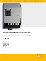
LiveU Xtender System Architecture
A video camera is connected to an LU live video uplink unit.
The LU unit is connected to the LiveU Xtender via LAN cable, USB cable or
via Wi-Fi (Wi-Fi Access Point and Wi-Fi Client).
The LU unit modems and the LiveU Xtender modems work together to
stream live audio and video from the field location to the LU-1000 or the
LU2000 central server, which is usually located in a broadcasting center.
Figure 2: LiveU LU and Xtender Architecture

Introducing the LiveU Xtender
9
What’s in the Suitcase?
The following describes the components provided in the Live Xtender suitcase:
• LU Xtender unit.
• A dedicated 12-volt power supply that connects to any standard
110VAC / 220VAC power source.
• A Wi-Fi Access Point and Wi-Fi Client, including the antennas of each.
• Rain cover.
NOTE The LiveU Xtender uses a standard Anton Bauer or a video-mount
battery. No batteries are provided.
NOTE Do not use other USB cables instead of the provided cables.
NOTE The LiveU Xtender has a standard tripod adapter. No tripod is
provided.
The following table lists the part numbers for the various cables and antennas
that can be used for Wi-Fi connectivity.
Table 1: Wi-Fi Connectivity Components
Part # Description
ANT00010 Antenna
ANT00011 Antenna
CBL00131 AC/DC External Harness, 120 cm
CBL00132
RJ45 External Harness, 100 cm
CBL00133 USB External Harness
CBL00158 Power Supply (from a triple USB)
CBL00159 Sealed Circular Ethernet Cable
CBL00160 Remote Antenna Kit LiveU Xtender-to-Power Cable
CBL00161 External-Charger-to-Remote-Antenna-Kit Power Cable, 60 cm
CBL00162 LU40/LU70-to-Remote-Antenna-Kit Ethernet Cable, 40 cm
CBL00173 N-type-to-RP-SMA Antenna Connection Cable, 75 cm
CBL00191 Remote Antenna Kit Antenna Connection Cable, 60 cm
CBL00190
Remote Antenna Kit Antenna Connection Cable, 24 cm

LiveU Xtender User Guide
10
LiveU Xtender Components
The following shows the various components of the LiveU Xtender:
Figure 3: LiveU Tripod Xtender
The Rooftop Xtender has the same connectors as the Tripod Xtender, shown
above. Its power is connected directly to the vehicle so that it automatically
powers on and off with the vehicle. It does not have a power button or DC
OUT on the bottom.
Figure 4: LiveU Rooftop Xtender
USB
LAN
(
Ethernet
)
DC IN
Wi-Fi Access Point
Three Antennas
Power On
Button
DC OUT

Introducing the LiveU Xtender
11
• LAN (Ethernet) Port: Can be connected to the Wi-Fi Client or directly to
an LU70 Ethernet port.
• USB Type B Connector (Gadget): For connecting to the LU70 or LU40.
• DC IN: 12-volt input source for connecting to a provided power supply.
• SIM Card Slots: Six numbered slots are provided for inserting SIM cards.
Slots 1 through 4 support all 3G/4G cellular bands.
Slots 5 and 6 support high-frequently bands 1,700 – 2,600 MHz.
The SIM card slots are protected by a cover that unscrews to open. The
following figure shows a detailed view of the SIM card slots, as well as the
correct direction for the insertion of these cards. Be sure to insert cards in
the correct direction.
Figure 5: SIM Card Slots
• Status LEDs: Three colored LEDs light up to indicate system status, such
as the link, alarm and streaming status, as described in the Status LEDs
section on page 12.
• Power Button (Tripod Xtender Only): To power ON, press and hold the
power button for approximately two seconds until it lights up. To power
OFF, press and hold the power button for approximately five seconds until
its light goes off.
• DC OUT: Can be used to power an external device.
• Battery Adapter: Enables the connection of an Anton Bauer or a
video-mount battery.
• Tripod Adapter (on the Tripod Xtender)

LiveU Xtender User Guide
12
Status LEDs
The LiveU Xtender has three status LEDs, shown below and in Figure 5.
Figure 6: Status LEDs
Upon power up, all LEDs light for three seconds and return to normal operation
after the software loads and the unit begins to work. The following table
describes the various states of the status LEDs.
Table 2: LiveU Xtender Status LEDs
LED State Description
All LEDs are off. Powering down.
Fault LED is red. Indicates an error, such as the following:
• Battery low
• High temperature
• Fan stuck
LU Link LED is green. Local-to-remote link (via Ethernet or wireless).
Tx LED is green. Normal video transmission operation (video uplink
is operational). This LED lights when one or more
modems are transmitting.
Tx
LU Link
Fault

13
2
LiveU Xtender Getting
Started
This chapter describes how to set up and get started using the LiveU Xtender.
Workflow Overview
Open the LiveU Xtender suitcase and check all the contents according to the
list provided in the What’s in the Suitcase? section on page 9. The following is
a recommendation for the order for setting up the LiveU Xtender.
Step 1
Page
14
Step 2
Page
18
Step 3
Page
23
Step 4
Page
24
Step 5
Page
25
Step 6
Page
26
Figure 7: Workflow – Setting Up the LiveU Xtender
Installing the Hardware
Connecting the LiveU
Xtender to the LU Device
Connecting the Power
Source
Turning On the LiveU
Xtender
Configuring the LiveU Xtender
Connection Type
Verifying the Connection

LiveU Xtender User Guide
14
The LiveU Xtender is supported in the LU70 software version 6.3 and up and in
the LU40 software version 2.0 and up.
Step 1, Installing the Hardware
Two options are available for installing the LiveU Xtender:
• Vehicle Rooftop Installation, page 14
• Tripod Installation, page 17
Vehicle Rooftop Installation
The sections that follow describe the considerations and limitations when
installing the LiveU Xtender on a vehicle’s rooftop, including:
• Direction Considerations, page 14
• Space Requirements, page 15
• Distance Between Antennas, page 15
• Distance from Other Metal Bodies, page 16
Direction Considerations
When mounting the LiveU Xtender on the vehicle, be sure to position it so that
its front is facing the front of the car and its back is facing the back of the car,
as shown below:
Figure 8: Positioning LiveU Xtender on a Vehicle Rooftop
Front of the vehicle
Back of
the vehicle

LiveU Xtender Getting Started
15
Cables connected to the LiveU Xtender must be attached from its back in order
to improve aerodynamic effects while the car is driving.
Figure 9: Positioning LiveU Xtender on a Vehicle Rooftop – Cable Connections
Space Requirements
Do not attach the LiveU Xtender to the vehicle’s roof surface. A minimum of
6.5 cm must be kept between the roof surface and the bottom side of the
LiveU Xtender, in order to provide adequate internal air circulation.
65mm MIN
Figure 10: LiveU Xtender Space Requirements – Bottom Side
Distance Between Antennas
Three shark fin antennas are provided to be installed on the vehicle rooftop
together with the LiveU Xtender. These antennas connect to the Wi-Fi link
access point.
Figure 11: Three Shark Fin Antennas
Mount this side facing the
fro
nt of the vehicle.
Mount this side
facing
the
back
of
the vehicle.

LiveU Xtender User Guide
16
A minimum distance of 50 mm is required between each antenna on the
vehicle roof. It is best to place the three antennas in a triangular formation on
the roof, as shown below:
Figure 12: Distance Between Antennas
Distance from Other Metal Bodies
If any additional metal equipment must be placed on the vehicle roof, it must
be at least 0.5 m from the LiveU Xtender unit.
NOTE If additional equipment beyond the LiveU Xtender must be placed on
the vehicle roof, it is strongly recommended to consult LiveU before
installing the LiveU Xtender.

LiveU Xtender Getting Started
17
Tripod Installation
The LiveU Xtender has a standard tripod connector on its bottom.
► To mount the LiveU Xtender:
1 Mount the LiveU Xtender using its tripod adapter.
2 Screw the three directional antennas onto the bar attached to the LiveU
Xtender, as shown below:
Figure 13: Mounting the Three Directional Antennas
Three Antennas

LiveU Xtender User Guide
18
Step 2, Connecting the LiveU Xtender to
the LU Device
The following describes how to connect the LiveU LU40 and LU70 unit to the
LiveU Xtender. The following three connection options are available:
• LAN Connection, page 18
• USB Connection (Only for the LU70), page 19
• Wi-Fi Connection, page 20
LAN Connection
Both the LU70 and the LU40 can be connected directly to the LiveU Xtender
via their LAN (Ethernet) port, as described below.
Rooftop
Tripod
Figure 14: LiveU Xtender LAN (Ethernet) Port
LU40
LU70
Figure 15: LU40 and LU70 LAN (Ethernet) Ports
On the back of the LU40, gently move the white plastic covering the Ethernet
port to the side and plug in the Ethernet cable.
LAN Ports

LiveU Xtender Getting Started
19
USB Connection
The LU70 can be connected directly to the LiveU Xtender via one of its four
USB ports, as described below.
NOTE The LiveU LU40 does not connect to the LiveU Xtender via USB.
Rooftop
Tripod
Figure 16: LiveU Xtender USB Port
Figure 17: LU70 USB Ports
Four USB Ports

LiveU Xtender User Guide
20
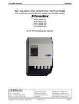
Wi-Fi Connection
The following is a summary of the connections for Wi-Fi communication
between the LU740/LU40 and the LiveU Xtender via Wi-Fi:
• LiveU Xtender connects to Wi-Fi Access Point via LAN cable. The
LAN (Ethernet) ports of the LiveU Xtender are shown in Figure 14.
• Wi-Fi Access Point has Wi-Fi antennas that communicate with the
antennas of the Wi-Fi Client.
• Wi-Fi Client has Wi-Fi antennas that communicate with the antennas of
the Wi-Fi Access Point.
• LU40/LU70 connects to Wi-Fi Client via LAN cable. The LAN
(Ethernet) ports of the LU70 and LU40 are shown in Figure 15.
► To set up the LiveU Xtender Wi-Fi connection:
1 Connect the Wi-Fi Access Point’s three antennas to three RF ports on the
Wi-Fi Access Point.
2 Connect the LiveU Xtender to the Wi-Fi Access Point via LAN cable. The
LAN (Ethernet) ports of the LiveU Xtender are shown in Figure 14.
The following figure illustrates the Wi-Fi connection between the LiveU
Xtender and the Wi-Fi Access Point.
CBL00173 75cm
CBL00173 75cm
CBL00173 75cm
RT Access Point
65mm MIN
60mm MIN
AC/DC CBL00131 120cm
AC/DC CBL00131
120cm
Power Source
LAN CBL00132 100cm
60mm MIN
Car Roof
Figure 18: LiveU Xtender to Wi-Fi Access Point Connection
Wi-Fi Antennas
LiveU Xtender
Mounted on
Vehicle Rooftop
Wi-Fi Access Point
/