RME M-32 DA Pro II-D User manual
- Category
- Musical Equipment
- Type
- User manual

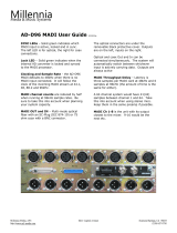
M-32 DA Pro II
POWER
OUTPUT 29
OUTPUT 30
OUTPUT 31
OUTPUT 32
OUTPUT 25
OUTPUT 26
OUTPUT 27
OUTPUT 28
OUTPUT 21
OUTPUT 22
OUTPUT 23
OUTPUT 24
OUTPUT 17
OUTPUT 18
OUTPUT 19
OUTPUT 20
OUTPUT 13
OUTPUT 14
OUTPUT 15
OUTPUT 16
OUTPUT 9
OUTPUT 10
OUTPUT 11
OUTPUT 12
OUTPUT 5
OUTPUT 6
OUTPUT 7
OUTPUT 8
OUTPUT 1
OUTPUT 2
OUTPUT 3
OUTPUT 4
29
30
31
32
25
26
27
28
21
22
23
24
17
18
19
20
13
14
15
16
9
10
11
12
5
6
7
8
1
2
3
4M-32 DA Pro II
Channel 17-24
LINE OUT LINE OUT LINE OUT
Channel 8-16 Channel 1-8
PSU 2
PSU 1
USB
MIDI
(SEC) NET
OUTOUT
OUT
MADI
WORD
MADI
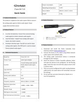
High-end Converter
User’s Guide
32-Channel 192 kHz D/A Converter
with MADI & Dante
M-32 DA Pro II-D
DANTE | MADI

RME M-32 DA Pro II-D User’s Guide

Table of Contents
1. Safety Precautions . . . . . . . . . . . . . . . . . . . . . . . . . . . . . . . . . . . . . . . . . . . . . . . . . . . . . . . . . . . . . . . . . . . . . . . Ê1
2. Introduction. . . . . . . . . . . . . . . . . . . . . . . . . . . . . . . . . . . . . . . . . . . . . . . . . . . . . . . . . . . . . . . . . . . . . . . . . . . . . Ê2
2.1. Firmware Update . . . . . . . . . . . . . . . . . . . . . . . . . . . . . . . . . . . . . . . . . . . . . . . . . . . . . . . . . . . . . . . . . . . . Ê3
2.2. Use of the Display and Encoder . . . . . . . . . . . . . . . . . . . . . . . . . . . . . . . . . . . . . . . . . . . . . . . . . . . . . . . . Ê3
2.2.1. Sections . . . . . . . . . . . . . . . . . . . . . . . . . . . . . . . . . . . . . . . . . . . . . . . . . . . . . . . . . . . . . . . . . . . . . . . . Ê3
2.2.2. Tabs . . . . . . . . . . . . . . . . . . . . . . . . . . . . . . . . . . . . . . . . . . . . . . . . . . . . . . . . . . . . . . . . . . . . . . . . . . . Ê4
2.3. Status Indicator Color Chart . . . . . . . . . . . . . . . . . . . . . . . . . . . . . . . . . . . . . . . . . . . . . . . . . . . . . . . . . . . Ê4
3. Hardware . . . . . . . . . . . . . . . . . . . . . . . . . . . . . . . . . . . . . . . . . . . . . . . . . . . . . . . . . . . . . . . . . . . . . . . . . . . . . . . Ê5
3.1. Hardware Specifications . . . . . . . . . . . . . . . . . . . . . . . . . . . . . . . . . . . . . . . . . . . . . . . . . . . . . . . . . . . . . . Ê6
3.2. Package Contents . . . . . . . . . . . . . . . . . . . . . . . . . . . . . . . . . . . . . . . . . . . . . . . . . . . . . . . . . . . . . . . . . . . Ê6
3.3. Power On . . . . . . . . . . . . . . . . . . . . . . . . . . . . . . . . . . . . . . . . . . . . . . . . . . . . . . . . . . . . . . . . . . . . . . . . . . . Ê6
3.4. Standby Switch . . . . . . . . . . . . . . . . . . . . . . . . . . . . . . . . . . . . . . . . . . . . . . . . . . . . . . . . . . . . . . . . . . . . . . Ê7
3.5. Ring Illumination . . . . . . . . . . . . . . . . . . . . . . . . . . . . . . . . . . . . . . . . . . . . . . . . . . . . . . . . . . . . . . . . . . . . . Ê7
3.6. Channel Labels with Integrated Metering . . . . . . . . . . . . . . . . . . . . . . . . . . . . . . . . . . . . . . . . . . . . . . . . Ê8
3.7. Meter Backlight Color and Intensity Reference. . . . . . . . . . . . . . . . . . . . . . . . . . . . . . . . . . . . . . . . . . . . Ê8
3.8. Replacing the Channel Labels . . . . . . . . . . . . . . . . . . . . . . . . . . . . . . . . . . . . . . . . . . . . . . . . . . . . . . . . . . Ê8
3.9. Control Section . . . . . . . . . . . . . . . . . . . . . . . . . . . . . . . . . . . . . . . . . . . . . . . . . . . . . . . . . . . . . . . . . . . . . . Ê9
3.10. Power Supplies . . . . . . . . . . . . . . . . . . . . . . . . . . . . . . . . . . . . . . . . . . . . . . . . . . . . . . . . . . . . . . . . . . . . . Ê9
3.11. Analog Line Output Connectors . . . . . . . . . . . . . . . . . . . . . . . . . . . . . . . . . . . . . . . . . . . . . . . . . . . . . . Ê10
3.12. Analog Line Levels . . . . . . . . . . . . . . . . . . . . . . . . . . . . . . . . . . . . . . . . . . . . . . . . . . . . . . . . . . . . . . . . . Ê10
3.13. DA Converter Specifications . . . . . . . . . . . . . . . . . . . . . . . . . . . . . . . . . . . . . . . . . . . . . . . . . . . . . . . . . Ê11
3.14. MADI Coaxial and SFP. . . . . . . . . . . . . . . . . . . . . . . . . . . . . . . . . . . . . . . . . . . . . . . . . . . . . . . . . . . . . . Ê11
3.15. Network Connection . . . . . . . . . . . . . . . . . . . . . . . . . . . . . . . . . . . . . . . . . . . . . . . . . . . . . . . . . . . . . . . Ê12
3.15.1. Combine ethernet ports (Switched mode). . . . . . . . . . . . . . . . . . . . . . . . . . . . . . . . . . . . . . . . . . Ê13
3.16. MIDI Connector. . . . . . . . . . . . . . . . . . . . . . . . . . . . . . . . . . . . . . . . . . . . . . . . . . . . . . . . . . . . . . . . . . . . Ê13
3.17. Word Clock . . . . . . . . . . . . . . . . . . . . . . . . . . . . . . . . . . . . . . . . . . . . . . . . . . . . . . . . . . . . . . . . . . . . . . . Ê13
3.18. USB 2.0 Type B Jack . . . . . . . . . . . . . . . . . . . . . . . . . . . . . . . . . . . . . . . . . . . . . . . . . . . . . . . . . . . . . . . Ê14
3.19. Mounting the Rack Adapter Brackets . . . . . . . . . . . . . . . . . . . . . . . . . . . . . . . . . . . . . . . . . . . . . . . . . Ê15
4. Accessories . . . . . . . . . . . . . . . . . . . . . . . . . . . . . . . . . . . . . . . . . . . . . . . . . . . . . . . . . . . . . . . . . . . . . . . . . . . Ê16
5. Dante Connectivity . . . . . . . . . . . . . . . . . . . . . . . . . . . . . . . . . . . . . . . . . . . . . . . . . . . . . . . . . . . . . . . . . . . . . . Ê17
5.1. Identifying a Device Remotely. . . . . . . . . . . . . . . . . . . . . . . . . . . . . . . . . . . . . . . . . . . . . . . . . . . . . . . . . Ê17
5.2. Changing the Device Name . . . . . . . . . . . . . . . . . . . . . . . . . . . . . . . . . . . . . . . . . . . . . . . . . . . . . . . . . . . Ê18
6. Quick Start (Dante). . . . . . . . . . . . . . . . . . . . . . . . . . . . . . . . . . . . . . . . . . . . . . . . . . . . . . . . . . . . . . . . . . . . . . Ê19
7. Warranty and Support . . . . . . . . . . . . . . . . . . . . . . . . . . . . . . . . . . . . . . . . . . . . . . . . . . . . . . . . . . . . . . . . . . . Ê21
7.1. Warranty . . . . . . . . . . . . . . . . . . . . . . . . . . . . . . . . . . . . . . . . . . . . . . . . . . . . . . . . . . . . . . . . . . . . . . . . . . Ê21
7.2. Support . . . . . . . . . . . . . . . . . . . . . . . . . . . . . . . . . . . . . . . . . . . . . . . . . . . . . . . . . . . . . . . . . . . . . . . . . . . Ê21
7.3. Support Contacts . . . . . . . . . . . . . . . . . . . . . . . . . . . . . . . . . . . . . . . . . . . . . . . . . . . . . . . . . . . . . . . . . . . Ê22
8. STATE Section . . . . . . . . . . . . . . . . . . . . . . . . . . . . . . . . . . . . . . . . . . . . . . . . . . . . . . . . . . . . . . . . . . . . . . . . . Ê23
8.1. Power State. . . . . . . . . . . . . . . . . . . . . . . . . . . . . . . . . . . . . . . . . . . . . . . . . . . . . . . . . . . . . . . . . . . . . . . . Ê23
8.1.1. Notification of Single Power Failure . . . . . . . . . . . . . . . . . . . . . . . . . . . . . . . . . . . . . . . . . . . . . . . . Ê23
8.2. Presets. . . . . . . . . . . . . . . . . . . . . . . . . . . . . . . . . . . . . . . . . . . . . . . . . . . . . . . . . . . . . . . . . . . . . . . . . . . . Ê24
8.2.1. Saving Presets . . . . . . . . . . . . . . . . . . . . . . . . . . . . . . . . . . . . . . . . . . . . . . . . . . . . . . . . . . . . . . . . . Ê24
8.2.2. Loading Presets . . . . . . . . . . . . . . . . . . . . . . . . . . . . . . . . . . . . . . . . . . . . . . . . . . . . . . . . . . . . . . . . Ê25
8.2.3. Loading Factory Default Settings . . . . . . . . . . . . . . . . . . . . . . . . . . . . . . . . . . . . . . . . . . . . . . . . . . Ê26
8.3. Device Lock . . . . . . . . . . . . . . . . . . . . . . . . . . . . . . . . . . . . . . . . . . . . . . . . . . . . . . . . . . . . . . . . . . . . . . . . Ê26
8.3.1. Locking the Device . . . . . . . . . . . . . . . . . . . . . . . . . . . . . . . . . . . . . . . . . . . . . . . . . . . . . . . . . . . . . . Ê26

8.3.2. Unlocking the Device . . . . . . . . . . . . . . . . . . . . . . . . . . . . . . . . . . . . . . . . . . . . . . . . . . . . . . . . . . . . Ê27
8.4. Front Panel Illumination. . . . . . . . . . . . . . . . . . . . . . . . . . . . . . . . . . . . . . . . . . . . . . . . . . . . . . . . . . . . . . Ê27
8.4.1. Dark Mode . . . . . . . . . . . . . . . . . . . . . . . . . . . . . . . . . . . . . . . . . . . . . . . . . . . . . . . . . . . . . . . . . . . . . Ê27
8.4.2. Changing the Meters to Peak or RMS Mode . . . . . . . . . . . . . . . . . . . . . . . . . . . . . . . . . . . . . . . . . Ê29
8.4.3. Persistent Clipping Notifications and Peak Hold . . . . . . . . . . . . . . . . . . . . . . . . . . . . . . . . . . . . . Ê29
8.4.4. Metering of Digital Signals. . . . . . . . . . . . . . . . . . . . . . . . . . . . . . . . . . . . . . . . . . . . . . . . . . . . . . . . Ê30
8.5. Remote Control Overview . . . . . . . . . . . . . . . . . . . . . . . . . . . . . . . . . . . . . . . . . . . . . . . . . . . . . . . . . . . . Ê31
8.5.1. Finding the Device on a Network . . . . . . . . . . . . . . . . . . . . . . . . . . . . . . . . . . . . . . . . . . . . . . . . . . Ê31
8.5.2. Web Remote . . . . . . . . . . . . . . . . . . . . . . . . . . . . . . . . . . . . . . . . . . . . . . . . . . . . . . . . . . . . . . . . . . . Ê32
8.5.3. JSON(OSC) Remote Control . . . . . . . . . . . . . . . . . . . . . . . . . . . . . . . . . . . . . . . . . . . . . . . . . . . . . . Ê34
8.5.4. JSON(OSC) Implementation Chart . . . . . . . . . . . . . . . . . . . . . . . . . . . . . . . . . . . . . . . . . . . . . . . . . Ê36
8.6. Monitor Fan Speed and Temperature . . . . . . . . . . . . . . . . . . . . . . . . . . . . . . . . . . . . . . . . . . . . . . . . . . Ê36
8.6.1. Adjust Fan Profile . . . . . . . . . . . . . . . . . . . . . . . . . . . . . . . . . . . . . . . . . . . . . . . . . . . . . . . . . . . . . . . Ê36
8.7. Device Information . . . . . . . . . . . . . . . . . . . . . . . . . . . . . . . . . . . . . . . . . . . . . . . . . . . . . . . . . . . . . . . . . . Ê38
9. INPUT Section. . . . . . . . . . . . . . . . . . . . . . . . . . . . . . . . . . . . . . . . . . . . . . . . . . . . . . . . . . . . . . . . . . . . . . . . . . Ê39
9.1. MADI Inputs. . . . . . . . . . . . . . . . . . . . . . . . . . . . . . . . . . . . . . . . . . . . . . . . . . . . . . . . . . . . . . . . . . . . . . . . Ê39
9.1.1. MADI at High Sample Rates . . . . . . . . . . . . . . . . . . . . . . . . . . . . . . . . . . . . . . . . . . . . . . . . . . . . . . Ê39
9.1.2. Connecting Two Identical MADI Signals for Redundancy . . . . . . . . . . . . . . . . . . . . . . . . . . . . . . Ê40
9.2. Dante Input . . . . . . . . . . . . . . . . . . . . . . . . . . . . . . . . . . . . . . . . . . . . . . . . . . . . . . . . . . . . . . . . . . . . . . . . Ê40
10. OUTPUT Section. . . . . . . . . . . . . . . . . . . . . . . . . . . . . . . . . . . . . . . . . . . . . . . . . . . . . . . . . . . . . . . . . . . . . . . Ê42
10.1. Routing Signals to the Outputs . . . . . . . . . . . . . . . . . . . . . . . . . . . . . . . . . . . . . . . . . . . . . . . . . . . . . . . Ê42
10.2. Analog Outputs. . . . . . . . . . . . . . . . . . . . . . . . . . . . . . . . . . . . . . . . . . . . . . . . . . . . . . . . . . . . . . . . . . . . Ê43
10.2.1. Adjusting the Output Line Level . . . . . . . . . . . . . . . . . . . . . . . . . . . . . . . . . . . . . . . . . . . . . . . . . . Ê43
10.2.2. Mute Analog Outputs . . . . . . . . . . . . . . . . . . . . . . . . . . . . . . . . . . . . . . . . . . . . . . . . . . . . . . . . . . . Ê44
10.3. MADI Outputs . . . . . . . . . . . . . . . . . . . . . . . . . . . . . . . . . . . . . . . . . . . . . . . . . . . . . . . . . . . . . . . . . . . . . Ê45
10.3.1. Setting the Output Channel Format and Frame Pattern. . . . . . . . . . . . . . . . . . . . . . . . . . . . . . . Ê45
10.3.2. MADI Daisy Chains . . . . . . . . . . . . . . . . . . . . . . . . . . . . . . . . . . . . . . . . . . . . . . . . . . . . . . . . . . . . . Ê46
10.3.3. MADI Port Mirroring . . . . . . . . . . . . . . . . . . . . . . . . . . . . . . . . . . . . . . . . . . . . . . . . . . . . . . . . . . . . Ê46
10.4. Dante Output. . . . . . . . . . . . . . . . . . . . . . . . . . . . . . . . . . . . . . . . . . . . . . . . . . . . . . . . . . . . . . . . . . . . . . Ê47
11. CLOCK Section . . . . . . . . . . . . . . . . . . . . . . . . . . . . . . . . . . . . . . . . . . . . . . . . . . . . . . . . . . . . . . . . . . . . . . . . Ê48
11.1. Clock Status . . . . . . . . . . . . . . . . . . . . . . . . . . . . . . . . . . . . . . . . . . . . . . . . . . . . . . . . . . . . . . . . . . . . . . Ê48
11.2. Leader Clock . . . . . . . . . . . . . . . . . . . . . . . . . . . . . . . . . . . . . . . . . . . . . . . . . . . . . . . . . . . . . . . . . . . . . . Ê48
11.2.1. Synchronizing to External . . . . . . . . . . . . . . . . . . . . . . . . . . . . . . . . . . . . . . . . . . . . . . . . . . . . . . . Ê50
11.3. Sample Rates Overview . . . . . . . . . . . . . . . . . . . . . . . . . . . . . . . . . . . . . . . . . . . . . . . . . . . . . . . . . . . . . Ê50
11.3.1. Number of Channels . . . . . . . . . . . . . . . . . . . . . . . . . . . . . . . . . . . . . . . . . . . . . . . . . . . . . . . . . . . Ê51
11.3.2. Selecting a Sample Rate . . . . . . . . . . . . . . . . . . . . . . . . . . . . . . . . . . . . . . . . . . . . . . . . . . . . . . . . Ê51
11.3.3. Effects of Sample Rate Changes on Existing Routing . . . . . . . . . . . . . . . . . . . . . . . . . . . . . . . . Ê51
11.4. Set Word Clock Output to Single Speed. . . . . . . . . . . . . . . . . . . . . . . . . . . . . . . . . . . . . . . . . . . . . . . . Ê52
12. Annex. . . . . . . . . . . . . . . . . . . . . . . . . . . . . . . . . . . . . . . . . . . . . . . . . . . . . . . . . . . . . . . . . . . . . . . . . . . . . . . . Ê53
Glossary . . . . . . . . . . . . . . . . . . . . . . . . . . . . . . . . . . . . . . . . . . . . . . . . . . . . . . . . . . . . . . . . . . . . . . . . . . . . . . Ê54
12.1. Regulatory Compliance . . . . . . . . . . . . . . . . . . . . . . . . . . . . . . . . . . . . . . . . . . . . . . . . . . . . . . . . . . . . . Ê54
12.1.1. CE Compliance . . . . . . . . . . . . . . . . . . . . . . . . . . . . . . . . . . . . . . . . . . . . . . . . . . . . . . . . . . . . . . . . Ê54
12.1.2. FCC Compliance . . . . . . . . . . . . . . . . . . . . . . . . . . . . . . . . . . . . . . . . . . . . . . . . . . . . . . . . . . . . . . . Ê54
12.1.3. Note on Disposal . . . . . . . . . . . . . . . . . . . . . . . . . . . . . . . . . . . . . . . . . . . . . . . . . . . . . . . . . . . . . . Ê55

WARNING
DO NOT OPEN DEVICE - RISK OF ELECTRIC SHOCK
The unit has non-isolated live parts inside. No user serviceable parts inside. Refer
service to qualified service personnel.
WARNING
MAGNETIC FIELD
The device uses magnets that can be harmful to pacemaker wearers.
Ensure the device is kept at least 90 cm (36 inches) from any active medical
implant (e.g. pacemakers).
CAUTION
General Safety Information
Read read the following safety information thoroughly and keep it in a safe place
for later reference.
KEEP AWAY FROM WATER AND MOISTURE
Prevent moisture and water from entering the device. Never leave objects
containing liquid on top or near the device. Do not use this product near water, i. e.
swimming pool, bathtub or wet basement. Danger of condensation inside - do not
turn on before the device has reached room temperature.
ENSURE PROPER VENTILATION
Do not cover the vents on the side of the unit. Ensure proper ventilation to avoid
overheating. The maximum ambient operating temperature of the device is 35° C
(95° F).
MAINS
The apparatus shall be connected to one or two mains socket outlets with a
protective earthing connection. Do not use defective power cords. Ensure that both
AC socket outlets for the device are easily accessible. In order to disconnect the
device from the mains completely, both mains plugs must be disconnected from
mains socket outlets.
Operation of the device is limited to the description in this manual.
NOTICE
Read the User Manual
Read the manual completely before using the product. It includes all information
necessary to use and operate this device.
RME M-32 DA Pro II-D User’s Guide
1. Safety Precautions | 1

2. Introduction
Thank you for purchasing the M-32 DA Pro II-D.
The M-32 DA Pro II-D is a versatile multichannel format converter with exceptional audio quality across
each of its channels. State-of-the art components from audiophile grade converters have been carefully
aligned to fit into a compact, 1 HU 19" rack device.
The device was designed to use the entire front for visual feedback on its state and configuration. A
display with encoder allows to perform all configurations directly at the device. Thirty-two custom-
inscribable labeling fields with backlight in shades of green, yellow, and red indicate the current signal
level.
Each analog channel can be individually adjusted to three different sensitivities that are perfectly
matched to the converter’s range. While this is usually implemented with digital 'trims', the M-32 DA Pro
II-D does the adjustment in the analog domain, ensuring that the converter’s signal to noise ratio is not
reduced when adapting to common line levels.
By integrating Audinate’s Dante® IP Core on a custom built RME FPGA platform, RME is not only
delivering a highly flexible solution but also gets one step closer to achieving a truly universal Audio
Networking experience. Any signal reaching the M-32 DA Pro II-D can be routed and streamed over IP
networks, including MADI signals!
The coaxial MADI port and a slot for a second, independent or redundant optical MADI port (SFP module)
can be used for daisy chaining, merging and converting MADI signals with lowest latencies.
The following manual provides a detailed explanation of features and their proper use. Please read the
safety instructions carefully.
Features described in this manual can change when the device firmware is updated. It is
therefore recommended to refer to the latest version of the manual available online.
Although the contents of this manual have been thoroughly checked for errors, RME can not guarantee
that it is correct throughout. RME does not accept responsibility for any misleading or incorrect
information within this guide. RME reserves the right to change specifications at any time without notice.
RME M-32 DA Pro II-D User’s Guide
2 | 2. Introduction

2.1. Firmware Update
New and improved features for this device, as well as bug fixes, are published on the RME website in the
download section as a firmware update. The update is provided as a compressed file with a .swu
extension and can be uploaded via web remote over USB or network.
To update the M-32 DA Pro II-D:
1. Connect the device by USB or network cable and open the Web Remote.
See: Section 8.5.1, “Finding the Device on a Network”
2. Download the current firmware from the RME website.
3. Unpack the compressed file.
4. Open the Settings in the Web Remote.
5. Within the Firmware Update section, press the Select .swu Firmware File Êbutton and locate the
unpacked file.
6. Press Start Firmware Update .
The unit retains all settings, including presets, when the firmware is upgraded.
2.2. Use of the Display and Encoder
The M-32 DA Pro II-D can be controlled directly at the unit. For this purpose, a display and an encoder
provide access to all features.
•Rotating the encoder when the standby screen is shown highlights one of four sections.
•Pushing the encoder when the screen is idle activates the previously active tab.
•Pushing the encoder when a section is highlighted opens the corresponding section.
2.2.1. Sections
All control items are categorized into four sections:
•STATE for general settings
•INPUT for audio input related settings
•OUTPUT for audio output related settings and routing
•CLOCK for digital clock related settings
RME M-32 DA Pro II-D User’s Guide
2.1. Firmware Update | 3

To access the INPUT section:
1. Rotate the encoder to highlight the "STATE" section
2. Rotate the encoder to highlight the "INPUT" section
3. Push the encoder to open the "INPUT" section.
2.2.2. Tabs
The STATE, INPUT and OUTPUT sections are further divided into tabs, which are shown when the
section is opened. Upon opening one of the four sections, a white cursor with a surrounding blue line is
shown to navigate between tabs and settings.
To close the section, move the cursor onto the minimize-icon and confirm by pressing the encoder.
2.3. Status Indicator Color Chart
Notifications on this device have been optimized for different screen sizes. They are unified across the
device display and the web remote and include a color bar that indicates the current state at a glance.
The following table shows the possible status indicator colors for reference.
Status Color Description
Warning red Requires a configuration change or matching
external signal.
Notice yellow There is a potential issue.
Notice (in progress) yellow with dots There is a temporary issue that should resolve
automatically.
No Routing light green In output section: Output is sending an empty
signal.
Issues with Input light green On standby screen in output section: Output is
working, but issues with input.
Good green Everything is working as expected.
Inactive grey Feature is not monitored or disabled.
RME M-32 DA Pro II-D User’s Guide
4 | 2.3. Status Indicator Color Chart

3. Hardware
Section 3.4, “Standby Switch”
Section 3.6, “Channel Labels with Integrated Metering”
Section 3.9, “Control Section”
Section 3.17, “Word Clock”
Section 3.16, “MIDI Connector”
Section 3.14, “MADI Coaxial and SFP”
Section 3.11, “Analog Line Output Connectors”
Section 3.15, “Network Connection”
Section 3.14, “MADI Coaxial and SFP”
Section 3.18, “USB 2.0 Type B Jack”
Section 3.10, “Power Supplies”
RME M-32 DA Pro II-D User’s Guide
3. Hardware | 5

3.1. Hardware Specifications
RME M-32 DA Pro II-D
EAN 42 6012336 350 5
Dimensions 440 x 44 x 243 mm (17.3 x 1.7 x 9.6 inches)
Weight 2.8 kg (6.2 lbs)
Package 560 x 315 x 115 mm (22.1 x 12.4 x 4.5 inches)
Conformity CE, FCC, WEEE, RoHS
Power supplies Dual 45 W 100-240 V AC
Power consumption typ. 30W, standby 0.5W
3.2. Package Contents
The package of the M-32 DA Pro II-D contains the following items:
•M-32 DA Pro II-D
•two rack mount brackets
•four screws for rack mount brackets
•two power cords
•MIDI breakout cable
•5 customizable channel labels
•printed manual
If any item is missing from a factory-sealed package, please contact your support
immediately.
3.3. Power On
The M-32 DA Pro II-D has a power off switch at the rear and a standby switch at the front.
Perform the following steps to power on the M-32 DA Pro II-D:
1. Ensure either or both power inlets are properly connected to a power source.
2. Toggle the mains switch at the back of the device to position I (down). The power indicator will light
up in red (Standby) or white (On). This depends on the state of the device before the rear switch was
toggled or the power cord removed.
3. If the device is in standby mode, push the standby switch to boot the device.
The M-32 DA Pro II-D features a dark mode which deactivates some or all lights of the front
panel. This can be used to let the device appear powered off when it is in fact powered on.
A short push on the standby switch or the the encoder deactivates this mode temporarily.
RME M-32 DA Pro II-D User’s Guide
6 | 3.1. Hardware Specifications

3.4. Standby Switch
The standby switch is used to power off the device when it is not in use. While in standby mode, the
device is completely powered down except for a red ring illumination. No signals are processed or
passed on.
Possible actions:
•When the device is in standby mode, a short push on the standby switch boots the
device.
•When the device is powered on, push and hold the standby switch for several
seconds in order to power down the device.
3.5. Ring Illumination
The following illumination patterns are possible:
No illumination
•There is no power at either of the two AC inlets.
•The power switch at the rear of the device is set to 'Off'.
•Dark mode has been activated.
Permanent red illumination
•The device is powered off but is receiving power at either one of the AC inlets.
Permanent white illumination
•The device is powered on and all systems are working without warning.
Alternating red/white illumination
•Something is not working properly. This is triggered when one of the four display
sections: STATE, INPUT, OUTPUT, or CLOCK signals a warning.
RME M-32 DA Pro II-D User’s Guide
3.4. Standby Switch | 7

3.6. Channel Labels with Integrated Metering
The use of customized channel labels helps in recurring and permanent installations. They inform the
user where the analog connections terminate.
The M-32 DA Pro II-D features 32 fields on the front panel, one for each analog output. Integrated
backlight in shades of green, yellow, and red represents the current level for each channel.
3.7. Meter Backlight Color and Intensity Reference
The following table describes the signal level represented by the backlight color. Each value corresponds
to full scale, which is equivalent to the reference level of the corresponding output.
Color Color name dBFS
Green -54 (barely visible in low light)
-40 (barely visible in daylight)
-20 (bright green)
Yellow -5 (strong yellow)
Orange -4
Red -1
Red flashing fast 0 (at least three consecutive samples)
Red flashing slow output muted
3.8. Replacing the Channel Labels
No tools are required to replace the channel labels. All 32 labels are printed or written onto a single
sheet.
Perform the following steps to replace the labels:
1. On the left side of the cover, place your fingertip into the recess and gently pull the cover towards you.
RME M-32 DA Pro II-D User’s Guide
8 | 3.6. Channel Labels with Integrated Metering

2. Remove the current label sheet that is held between cover and device.
3. Place a new label sheet onto the cover.
4. Put the cover back into its place, aligning the centered metal plate first. It snaps into place
magnetically.
It is possible to prepare your own paper cutouts in case you frequently need to label the
fields. A PDF template is available upon request from your support. When choosing the
paper type, ensure that its thickness allows sufficient light to pass through.
3.9. Control Section
The M-32 DA Pro II-D can be configured at the device.
To do so, the TFT display shows a menu. The adjacent encoder knob is used to navigate and change
settings.
The encoder can be pushed in order to activate an item,
and rotated left and right in order to select an item.
If the device is powered on but the display shows no content, dark mode may be active.
Rotate the encoder to temporarily bypass this mode and show the display.
3.10. Power Supplies
The M-32 DA Pro II-D has two internal power supplies (PSUs) that are connected via IEC C14 inlets
labeled "PSU 1" and "PSU 2" at the rear of the device. The power supplies are designed with a wide-input
voltage range, accommodating a variety of power sources. They are short-circuit-proof, have an
integrated line-filter, are fully regulated against voltage fluctuations, and suppress mains interference.
RME M-32 DA Pro II-D User’s Guide
3.9. Control Section | 9

The inlets are labeled in the sequence they appear when looking from the front of the
device. This helps identifying the active power source on the display.
The power switch next to the two inlets internally disconnects the line connection of the C14 inlets to the
power supplies. Ground and neutral will remain connected.
Lockable IEC plugs
The inlets can be used with special IEC power cords that have a lockable connector. Please contact a
local distributor to purchase these power cords if needed.
3.11. Analog Line Output Connectors
The rear of the M-32 DA Pro II-D features 25-pin D-sub connectors labeled "LINE OUT" with Tascam®-
pinout.
The short circuit protected, low impedance balanced line outputs at the D-Sub connectors
do not operate servo balanced. When connecting unbalanced equipment, make sure pin 3
("cold") of the output is not connected. A connection to ground may cause a decreased
THD (higher distortion) and increased power consumption!
3.12. Analog Line Levels
The M-32 DA Pro II-D can be adjusted to the following reference levels:
Reference 0 dBFS Headroom at
+4dBu
Other RME
devices
+24 +24 dBu 20 dB -
+19 +19 dBu 15 dB LoGain
RME M-32 DA Pro II-D User’s Guide
10 | 3.11. Analog Line Output Connectors

Reference 0 dBFS Headroom at
+4dBu
Other RME
devices
+13 +13 dBu 9 dB +4 dBu
When set to +24, analog outputs comply with RP 155:2014 - SMPTE Recommended
Practice.
3.13. DA Converter Specifications
Line Out 1-32:
•Resolution: 24 bit
•Output level switchable per channel +24 dBu, +19 dBu, +13 dBu @ 0 dBFS
•Outputs DC coupled, fully symmetrical signal path ("truly balanced")
•Output impedance: 200 Ohm balanced, 100 Ohm unbalanced
•Signal to Noise Ratio (SNR) @ 13 dBu: 116.0 dB RMS unweighted, 119.0 dB(A)
•Signal to Noise Ratio (SNR) @ 19 dBu: 116.3 dB RMS unweighted, 119.3 dB(A)
•Signal to Noise Ratio (SNR) @ 24 dBu: 116.5 dB RMS unweighted, 119.8 dB(A)
•Frequency response @ 44.1 kHz, -0.1 dB: 0 Hz – 22 kHz
•THD @ -1 dBFS: < -113 dB, < 0.00022 %
•THD+N @ -1 dBFS: < -111 dB, < 0.00028 %
•Channel separation: > 110 dB
3.14. MADI Coaxial and SFP
The rear of the M-32 DA Pro II-D features coaxial and SFP MADI (AES10-2003) I/O.
Each input receives up to 64 audio channels. Auto Input (see Section 9.1.2, “Connecting Two Identical
MADI Signals for Redundancy”) can be activated to treat both inputs as one.
The coaxial BNC connector accepts coaxial cables with 75 Ω impedance.
The "small form-factor pluggable" connector (SFP) accepts 125 MBit/s transceivers with LC connectors,
1310mm wavelength and multi-mode (MM) or single-mode (SM) cable support. These must be
purchased separately (see Section 4, “Accessories”).
An SFP module has indicators to distinguish transmitter (▼) and receiver (▲). It can be inserted and
RME M-32 DA Pro II-D User’s Guide
3.13. DA Converter Specifications | 11

removed while the device is powered on (hot plugging). Any plugged in connector must be removed
before unlocking the SFP. Unlock and remove by pulling its integrated wire latch outward.
The wire latch of the SFP module is color coded. Black stands for the most common
multimode module, blue stands for single mode which allows longer distance
transmissions. It is possible, but not reliable to connect single mode transceivers with
multi mode transceivers. Avoid this by always confirming that connected devices match
the specification of the fiber optic cable.
On the device, the characteristics and state of the signal at either input can be inspected in the
The presence or loss of a signal at either port is indicated on the standby screen and main menu if
•the input port is selected as clock master, or
•its audio channels are routed in the OUTPUT section.
When using the web remote, the characteristics and state of the signal at either input can be inspected in
the CLOCK section.
3.15. Network Connection
On the rear of the M-32 DA Pro II-D, two RJ45 connectors labeled NET (PRI) and NET (SEC) provide
ethernet connectivity. The supported link speeds are 1 Gb/s and 100 Mb/s.
A green LED (left, LINK) signals a successful link. A yellow LED (right, ACT) signals network traffic
(blinking).
Both straight and crossover cables can be used (Auto MDI-X). Cable lengths of up to 100m are supported
when using Cat 5e or higher classification.
The network ports are used to send and receive:
•up to 64 audio channels when connected to a Dante® network, and
•remote status/control with HTTP over IP routed networks.
The current link state is also shown on the display of the M-32 DA Pro II-D.
RME M-32 DA Pro II-D User’s Guide
12 | 3.15. Network Connection

Two network port icons in the menu reveal the following
states:
Icon Description
No link - cable not connected
Negotiating link with other endpoint
Successful link with speed of 100 MBit/s
Successful link with speed of 1 GBit/s
3.15.1. Combine ethernet ports (Switched mode)
The two ethernet ports can be configured with the Dante Controller in Device View > Network Config >
Dante Redundancy. If both ports are connected to the same network, for example to create a daisy-chain
of several M-32 DA Pro II-D devices, then the setting must be changed to Switched. In the default mode,
the device is configured so that each port connects to one of two separate networks (Redundancy).
If the unit has been configured to connect the primary and secondary port internally (switched mode),
devices attached to the two ports can communicate both with each other and with the M-32 DA Pro II-D.
This is indicated in the menu with a horizontal line ('-') between the network ports.
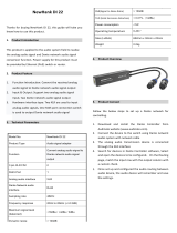
3.16. MIDI Connector
The M-32 DA Pro II-D can be controlled with MIDI SysEx commands from either a physical MIDI
connection or a MIDI over MADI signal. A MIDI breakout cable is included with the device.
Figure 1. MIDI Breakout Cable Wiring Diagram
The M-32 DA Pro II-D does not serve as a MIDI to/from MIDI over MADI converter. It does
not pass on incoming MIDI signals except for SysEx remote control information.
3.17. Word Clock
Word clock can be sent and received via 75 Ω coaxial cabling at the corresponding BNC connectors. The
RME M-32 DA Pro II-D User’s Guide
3.16. MIDI Connector | 13

cable length should not exceed 100 m (330 ft).
The input is terminated with 75 Ω internally. To pass on the word clock to other devices,
use the word clock output. Do not connect a T-adapter to the word clock input.
The state of an incoming word clock signal can be accessed in the CLOCK section.
Possible States:
•A green indicator shows that the signal is currently in sync with the chosen clock master.
•An orange indicator means that a word clock is received but is not in sync.
•A red indicator means that word clock is chosen as master, but a signal is not present or has a
different sample rate than the chosen one.
3.18. USB 2.0 Type B Jack
The USB jack at the rear of the M-32 DA Pro II-D provides an alternative connection method for web
remote control when a network connection is not available.
When connecting the M-32 DA Pro II-D with a standard ("printer") USB 2.0 cable to a current
MicrosoftÊWindows™ or AppleÊmacOS™ operating system, a network adapter will be automatically
installed. This does not require additional drivers. The device can then be remotely controlled by opening
the URL http://172.20.0.1.
RME M-32 DA Pro II-D User’s Guide
14 | 3.18. USB 2.0 Type B Jack

The USB port cannot be used to stream audio signals.
3.19. Mounting the Rack Adapter Brackets
When the device should be mounted in a 19" rack, the rack adapter brackets must be mounted first.
Mount each bracket with two screws using a Philips PH-1 screwdriver.
Do not use screws other than the ones included. Using longer screws can damage the
device internally!
Never insert the screws without the rack adapter bracket. This could damage of the device!
RME M-32 DA Pro II-D User’s Guide
3.19. Mounting the Rack Adapter Brackets | 15

4. Accessories
RME offers several optional components for the M-32 DA Pro II-D:
Part Number Description
Analog breakout cables
AO25-8XPro3 Analog breakout cable 25-pin D-sub to 8 x XLR male, 3 m (9.9 ft)
AO25-8XPro5 Analog breakout cable 25-pin D-sub to 8 x XLR male, 5 m (16.4 ft)
AO25-8XPro10 Analog breakout cable 25-pin D-sub to 8 x XLR male, 10 m (33 ft)
19" XLR breakout panels
DTOX-16 O 2x D-sub to 16x XLR Output
MADI Optical cables
MADI1S MADI Optical Cable, Simplex, 1m (3.3 ft)
MADI3D MADI Optical Cable, Duplex, 3m (9.9 ft)
MADI6D MADI Optical Cable, Duplex, 6m (19.8 ft)
MADI10D MADI Optical Cable, Duplex, 10m (32.8 ft)
MADI20D MADI Optical Cable, Duplex, 20m (65.6 ft)
MADI50D MADI Optical Cable, Duplex, 50m (164 ft)
SFP Modules
MADI-SFP-MM MADI optical multi-mode module, 2 km, LC
MADI-SFP-SM MADI optical single-mode module, 20 km, LC
Third party accessories available from independent global retailers:
Optional power cords with locking mechanism
Manufacturer Part Number Description
Schurter 6051.2032 CN CORDSET 10A 2.0M V-LOCK
Schurter 6051.2003 EU CORDSET 10A 2.0M V-LOCK
Schurter 6051.2031 JP CORDSET 10A 2.0M V-LOCK
Schurter 6051.2008 UK CORDSET 10A 2.0M V-LOCK
Schurter 6051.2001 US CORDSET 10A 2.0M V-LOCK
RME M-32 DA Pro II-D User’s Guide
16 | 4. Accessories
Page is loading ...
Page is loading ...
Page is loading ...
Page is loading ...
Page is loading ...
Page is loading ...
Page is loading ...
Page is loading ...
Page is loading ...
Page is loading ...
Page is loading ...
Page is loading ...
Page is loading ...
Page is loading ...
Page is loading ...
Page is loading ...
Page is loading ...
Page is loading ...
Page is loading ...
Page is loading ...
Page is loading ...
Page is loading ...
Page is loading ...
Page is loading ...
Page is loading ...
Page is loading ...
Page is loading ...
Page is loading ...
Page is loading ...
Page is loading ...
Page is loading ...
Page is loading ...
Page is loading ...
Page is loading ...
Page is loading ...
Page is loading ...
Page is loading ...
Page is loading ...
Page is loading ...
-
 1
1
-
 2
2
-
 3
3
-
 4
4
-
 5
5
-
 6
6
-
 7
7
-
 8
8
-
 9
9
-
 10
10
-
 11
11
-
 12
12
-
 13
13
-
 14
14
-
 15
15
-
 16
16
-
 17
17
-
 18
18
-
 19
19
-
 20
20
-
 21
21
-
 22
22
-
 23
23
-
 24
24
-
 25
25
-
 26
26
-
 27
27
-
 28
28
-
 29
29
-
 30
30
-
 31
31
-
 32
32
-
 33
33
-
 34
34
-
 35
35
-
 36
36
-
 37
37
-
 38
38
-
 39
39
-
 40
40
-
 41
41
-
 42
42
-
 43
43
-
 44
44
-
 45
45
-
 46
46
-
 47
47
-
 48
48
-
 49
49
-
 50
50
-
 51
51
-
 52
52
-
 53
53
-
 54
54
-
 55
55
-
 56
56
-
 57
57
-
 58
58
-
 59
59


RME M-32 DA Pro II-D User manual
- Category
- Musical Equipment
- Type
- User manual
Ask a question and I''ll find the answer in the document
Finding information in a document is now easier with AI
Related papers
Other documents
-
 Millennia AD-D96 User guide
-
 infobitav DX-T-22 User guide
-
 INTERSTATE AUDIO NewHank DI 22 Operating instructions
-
 RME Audio MADIface XT User manual
-
 RME Audio M-32 AD Pro User manual
-
Alesis Hammerfall DSP System User manual
-
 DirectOut Technologies PRODIGY.MP User manual
-
RME Audio Hammerfall HDSP 9632 User manual
-
Crystal Vision MADDA111 User manual
-
Clear-Com Eclipse HX Median User guide


