Page is loading ...

CYPRESS WELDING EQUIPMENT INC.
A DIVISION OF WELD TOOLING CORPORATION
280 Technology Drive • Canonsburg, PA 15317-9564 USA
Telephone: 1-412-331-1776 • 1-800-245-3186 • Fax: 1-412-331-0383
http://www.cypressweld.com
INSTRUCTIONS
AND
PARTS MANUAL
CW-18
CIRCLE WELDER
Please record your equipment identication information below for future reference. This information can be found
on your machine nameplate.
Model Number
Serial Number
Date of Purchase
Whenever you request replacement parts or information on this equipment, always supply the information you
have recorded above.
LIT-CW18-IPM-0810

2
PROTECT YOURSELF AND OTHERS FROM SERIOUS INJURY OR DEATH. KEEP
CHILDREN AWAY. BE SURE THAT ALL INSTALLATION, OPERATION, MAINTENANCE
AND REPAIR PROCEDURES ARE PERFORMED ONLY BY QUALIFIED INDIVIDUALS.
EQUIPMENT DAMAGE
POSSIBLE.
ELECTRIC SHOCK can kill.
1) The equipment is not waterproof.
Using the unit in a wet environment
may result in serious injury. Do not
touch equipment when wet or standing
in a wet location.
2) The unused connectors have power on
them. Always keep the unused
connectors covered with the supplied
protective panels. Operation of the
machine without the protective panels
may result in injury.
3) Never open the equipment without
rst unplugging the power cord or
serious injury may result.
4) Verify the customer-supplied power
connections are made in accordance
with all applicable local and national
electrical safety codes. If none exist,
use International Electric Code (IEC)
950.
5) Never remove or bypass the equip-
ment power cord ground. Verify the
equipment is grounded in accordance
with all applicable local and national
electrical safety codes. If none exist,
use International Electric Code (IEC)
950.
READ INSTRUCTIONS.
Read the instruction manual before in-
stalling and using the equipment.
1) Do not plug in the power cord with
out rst verifying the equipment
is OFF and the cord input voltage is
the same as required by the machine
or serious damage may result.
2) Always verify both the pinion and
wheels are fully engaged before
applying power or equipment damage
may occur.
3) Do not leave the equipment
unattended.
4) Remove from the worksite and store in
a safe location when not in use.
1) Never try to stop the pinion from
moving except by removing power or
by using the STOP control.
2) Do not remove any protective panels,
covers or guards and operate
equipment.
MOVING PARTS can
cause serious injury.
FALLING EQUIPMENT
can cause serious
personal injury and
equipment damage.
Faulty or careless user installation is
possible. As a result, never stand or
walk underneath equipment.

3
PRECAUTIONS:
1) Some plasma or welding cables are strong sources of high frequency interference.
NEVER lay a plasma or welding cable across the controls of the machine.
2) Always physically separate the plasma or welding cable leads from the machine
cables. For example, the plasma or welding cable leads should NEVER be bundled
with a pendant cable or the machine power cord. Maximize the separation between
any machine cables and the plasma or welding cables.
3) Strictly follow the grounding procedures specied for the plasma or welding unit.
NOTE: Some plasma and welding units produce exceptionally large amounts of
high frequency noise. They may require a grounding rod be driven into the earth
within six feet (2 meters) of the plasma or welding unit to become compatible with an
automatic cutting or welding process.
4) If the high frequency is produced using a spark gap, adjust the points so the gap is as
small as possible. The larger the gap, the higher the voltage and the higher the
interference.
5) Some plasma or welding units will inject high frequency interference into the AC
power line. Use separate power line branches whenever possible to power the plasma
or welding source and the machine. Do not plug them into the same outlet box.
6) High frequency noise may enter the machine through the plasma or welding supply
remote contactor leads. Some plasma and welding sources can produce noise spikes
of up to several thousand volts. These sources are not compatible with automated
cutting and welding equipment. It is recommended that the remote contactor leads
on these plasma or welding sources not be connected to the machine. An alternate
solution is to purchase a separate remote contactor isolation box.
HIGH FREQUENCY WARNINGS
WARNING: HIGH FREQUENCY CAN EFFECT MACHINE
OPERATION AND THEREFORE, WELD QUALITY.
SPECIAL PRECAUTIONS ARE REQUIRED WHEN USING PLASMA,
TIG OR ANY WELDING PROCESS THAT USES HIGH FREQUENCY
TO STRIKE AN ARC.
Read the precautions below before installing and using the equipment.


5
TABLE OF CONTENTS
CW-18 CIRCLE WELDER
INSTRUCTIONS AND PARTS MANUAL
PAGE
Patents Pending
6 ........ Introduction / Set-up and Operation
8 ........ LDC-NA3S NA-3 Wire Feeder Controls
10 ....... CWO-6210-CW18 Rotation Controls
11 ....... Technical Data / Dimensions
12 ....... CWO-1800 CW-18 Circle Welder / Parts List
13 ....... CWO-1800 CW-18 Circle Welder / Exploded View
14 ....... CWO-1800 CW-18 Circle Welder / Wiring Diagram / Electrical Component Chart
15 ....... CWO-3133 CW-11/CW-18 Collector with Power Racker
16 ....... CWO-1840 CW-18 Racking System / Exploded View / Parts List
16 ....... CWO-1690 Horizontal Racker / Exploded View / Parts List
17 ....... CWO-3165 CW-18 Housing Assembly / Exploded View / Parts List
17 ....... CWO-3205-11 7" Cam Assembly / Exploded View / Parts List
18 ....... CWO-3313 Brush Holder & Support Assembly / Exploded View / Parts List
18 ....... CWO-3359 Transmission 5:1 / Exploded View / Parts List
19 ....... CWO-3432 CW-18 Shaft Assembly / Exploded View / Parts List
19 ....... CWO-3490 Flux Hopper Assembly / Exploded View / Parts List
20 ....... CWO-3498-11 Wire Reel Assembly / Exploded View / Parts List
20 ....... CWO-3506 4066 Motor Assembly / Exploded View / Parts List
21 ....... CWO-3528 2" Flange Bearing w/Fasteners / Exploded View / Parts List
21 ....... CWO-3531 Motor & Transmission Plate Assembly / Exploded View / Parts List
22 ....... CWO-3534 Slide Bar Assembly / Exploded View / Parts List
22 ....... CWO-3537 Guard Assembly CW-18 / Exploded View / Parts List
23 ....... CWO-3538 CW-18 Camshaft & Spacer Assembly / Exploded View / Parts List
24 ....... CWO-3931 Small Brush Assembly / Exploded View / Parts List
24 ....... CWO-3969 Terminal Block Assembly / Exploded View / Parts List
25 ....... CWO-3971 Control Cable / Detail View / Parts List
25 ....... CWO-2978 Feeder Control Box Cable / Detail View / Parts List
26 ....... CWO-3974 33# Load Spring Assembly / Exploded View / Parts List
27 ....... CWO-6210-CW18 Rotation Control / Exploded View / Parts List
28 ....... CWO-6210-CW18 Rotation Control / Wiring Diagram / Electrical Component Chart
29 ....... CWO-3690-_ K231 Sub Arc Gun
30 ....... CWO-3710-_ Sub Arc Gun Assembly
31 ....... 3-Jaw Expandable Chucks
32 ....... Optional Motorized Racking Equipment / CWO-1640-M / Exploded View / Parts List
32 ....... Optional Motorized Racking Equipment / CWP-3363 / Exploded View / Parts List
33 ....... Optional Motorized Racking Equipment / CWP-3351 / Exploded View / Parts List
34 ....... Optional Motorized Racking Equipment / PRS-1075 / Exploded View / Parts List
35 ....... Optional Motorized Racking Equipment / PRS-1100 / Exploded View / Parts List
36 ....... Optional Motorized Racking Equipment / PRS-1091-WD Wiring Diagram / Parts List
37 ....... Preventative Maintenance / CW-18 Circle Welder
40 ....... Warranty

6
INTRODUCTION
The CW-18 (CWO-1800) Circle Welder is designed for welding of nozzles into vessels or
domed heads utilizing SUB-ARC, MIG or FLUX CORED PROCESS, with gas shielding. The
CW-18 mounts on a 3-Jaw Chuck welding diameter 6” to 50” O.D.
Features:
• Wire feeder with one set of drive rolls.
• 1/12 HP P.M. motor and rotational speed control.
• 600 AMP gun & cable assembly.
• Internal to NA3
• 50 ft. (15 m) power cable.
• 50 ft. (15 m) gas shielding hose.
• 50 ft. (15 m) weld cable.
• Quick disconnects for all cables.
• Pre and post ow controls.
• Wire reel adaptor for 60 lb. (27 kg) spools.
• Adjustable vertical and horizontal torch positioning system.
• Rise and fall cam assembly with 5” (125 mm) of travel.
• Brushes and collector rings for welding current, rated at 600 AMPS 100% duty cycle.
• Brushes and collector rings for all controls, eliminates cable and hose wrap.
NA 3 Control Provides:
• Wire Spool (amperage) control
• Voltage Control
• Wire burn back
• Weld contact
• Cold wire switch
• Weld start parameter adjustment
• Weld Crater parameter adjustment
SET-UP AND OPERATION:
POWER SOURCE:
Please refer to the included Lincoln NA3 user’s manual for welding power source requirements
and system set-up.
GUNS AND CABLES:
All circle welders come equipped with a gun and cable assembly. It is our recommendation that
at least once a week the liner be taken out of the cable and soaked overnight in a solvent solu-
tion. To keep the wire moving it is also recommended that a felt clip be saturated with a product
like Ferro Slick and feed through the incoming tube of the wire feeder at least once a day.
ADDITIONAL CABLES:
The circle welders are supplied with the following cables:
1. CWO-3971 50’ (15 m) power cable that connects the power source to the cable
connector on the top gear of the machine.
2. CWO-3040 50’ (15 m) weld cable that connects the lead coming out of the top of the
machine using the quick connect connector to your power supply.
3. CWO-9406 50’ (15 m) gas shielding hose that connects the gas tting on the top of the
shaft to your shielding gas supply.

7
SET-UP AND OPERATION CONTINUED:
WIRE SPEED AND VOLTAGE ADJUSTMENT:
The wire speed control on the front of the LDC-NA3S Wire Feed Control box has a dial that is
calibrated directly in inches per minute. Set the voltage using the control on the power source.
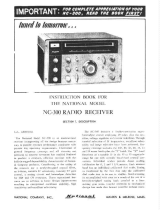
RISE AND FALL OF THE CAM:
All circle welders are equipped with a rise and fall cam as-
sembly. The cam assembly must be aligned before any other
settings can be made. To align the cam rotate the machine so
the horizontal rack is parallel to the pipe, then adjust the gun
holder so it is perpendicular to the horizontal rack. Position
torch tip to top dead center of joint. Loosen the set screws in
the brass block on the cam, and rotate the cam to the vertical
position as shown. Refasten set screws.
CAM SETTING:
The cam setting is equal to distance “B” subtracted from
distance “A”.
Example:
Let A=3 and B=2
3-2=1
The cam setting is 1.
WHEEL ADJUSTMENT:
The CW-18 Racking System CWO-1840 and the Small Vertical Racker
CWO-1690 are equipped with adjustable wheels. Always check these
components for proper wheel adjustment before using the machine. The
wheels need adjustment if you can cock or wiggle the components out of
alignment. The wheels should be snug but not prohibit movement along
the path of travel. The wheels with the hex stand offs are adjustable. To
adjust the wheels, loosen the hex bolt (A) until the adjustable bushing (B)
can be rotated. Correct the wheel alignment by rotating the adjustable
bushing (B). Once adjusted, hold the adjustable bushing (B) while
tightening the hex bolt (A). Recheck alignment.
MACHINE CONTROLS:
Operational parameters can be set using the two control boxes. Please
refer to the section in this manual entitled CWO-6210-CW18 Rotational
Control for descriptions of the various speed and directional capabilities. For the LD-NA3S NA-3 Wire
Feeder Control; refer to the supplied NA-3 Semiautomatic Wire Feeder Manual from Lincoln Electric.
MAKING A WELD:
1. Position the gun to start position using the CWO-1840 Racking System.
2. Connect the ground cable to the workpiece. The ground cable must make good electrical
contact with the work.
3. Position the electrode in the joint. The end of the electrode may be lightly touching the
work.
4. With manual/auto switch in the “OFF” position, set rotation direction and speed.
5. Weld process and rotation are both started by throwing the manual/auto switch to auto.
6. Weld process and rotation are stopped by throwing the manual/auto switch to “OFF”.
Cam
Torch
Holder Pipe
BABA
A
B


9
LDC-NA3S NA-3 WIRE FEEDER CONTROLS, CONT’D.
NOTE: For further information refer to Lincoln Electric NA-3 Operator’s Manual.
A. AMMETER
Indicates current only while welding.
B. CIRCUIT BREAKER
Protects the circuit from sever wire feed motor overload and short circuits. Press to reset.
Locate and correct the cause for overload.
C. VOLTMETER (Standard)
Indicated welding voltage only while welding. Also indicates OCV below 60 volts.
D. START
Push-button beings the welding cycle
E. STOP
Push-button initiated the stopping cycle at the end of the weld.
F. INCH UP & INCH DOWN
Press to inch electrode at the speed set by “Inch Speed” control on inner panel.
G. CURRENT CONTROL
Adjusts wire feed speed to control welding current.
H. TRAVEL
Turn to “Off” for no travel; “Hand Travel” for travel without welding; “Automatic Travel” for
welding operations. Speed and direction of travel are controlled by the travel mechanisms
control.
I. VOLTAGE CONTROL
Adjust arc volts by controlling power source output voltage.
J. CONTROL POWER
Turns input control power “On” and “Off”. Also used as an emergency “Off” in case of
malfunction.
*For further information on NA-3 Wire Feeder and controls, refer to Lincoln Electric NA-3
Wire Feeder Operators Manual.

10
CWO-6210-CW18 ROTATION CONTROLS
SPEED CONTROL:
Controls the speed in which the machine travels. The depicted lines 0 to 100 should not be con-
strued as inches per minute of travel. They should be considered as reference points only.
TRAVEL DIRECTION:
Controls the direction in which the machine will travel. Select forward for clockwise rotation,
brake for stop, and reverse for counterclockwise rotation.
ON/OFF SWITCH:
The on/off switch enables/disables power to the rotation control box.
PILOT LIGHT:
The pilot light indicates whether the machine is on/off as dictated by the on/off switch.
On/Off Switch
Pilot Light
Travel Direction
Speed Control

11
Input Voltage: 0-600 amps
Amperage: 115 VAC
Voltage: 0-50
Wire Sizes: 1/16’’-7/32’’ (1.6-5.6 mm)
Rotation Speed: .06-.72 rpm
Cam Range: 0’’-7’’ (0-175 mm)
Welding Radius: 0’’-25” (0-635 mm)
Shielding Gas: Solenoid Control
Height: 43’’ (1092 mm)
Net Weight: 360 lbs. (163.6 kg)
Shipping Weight: 490 lbs. (222.3 kg)
DIMENSIONS:
TECHNICAL DATA
36”
(914 mm)
70”
(1778 mm)
43”
(1092 mm)
36.5”
(927 mm)

12
CWO-1800 CW-18 CIRCLE WELDER / PARTS LIST
ITEM QTY PART NUMBER DESCRIPTION
1 1 CWO-1123 CONTROL MT. SPACER BLOCK
2 1 CWO-1124 CW-18 CONTROL MT. PLATE
3 1 CWO-1690 LARGE HORIZONTAL RACK
4 1 CWO-1811 NA-3S MOUNT PLATE
5 1 CWO-1812 FLUX HOPPER SUPPORT
6 1 CWO-1813 WIRE FEEDER BRACKET
7 1 CWO-1814 INSULATOR PLATE
8 1 CWO-3133 COLLECTOR, CW-11/CW-18
9 1 CWO-1816 WIRE FEEDER ADAPTOR
10 1 CWO-3931 BRUSH RETAINER ASSEMBLY
11 1 CWO-1840 CW-18 RACKING SYSTEM
12 1 CWO-2020 FLUX RECOVERY SYSTEM (OPTIONAL)
13 1 CWO-3165 CW-18 HOUSING ASSEMBLY
14 1 CWO-3205-11 7’’ CAM ASSEMBLY CW-18
15 1 CWO-3218 CABLE SUPPORT BAR
16 1 CWO-3312 LIFTING LUG WELDMENT
17 1 CWO-3313 BRUSH HOLDER & SUPPORT
18 1 CWO-3359 TRANSMISSION SW-5:1 ASSEMBLY
19 1 CWO-3432 CW-18 SHAFT ASSEMBLY
20 1 CWO-3498-11 WIRE REEL ASSEMBLY CW-18
21 1 CWO-3506 4066 MOTOR ASSEMBLY
22 2 CWO-3528 2’’ FLANGE BEARING W/ FASTENERS
23 1 CWO-3531 MOTOR & TRANSMISSION PLT. ASSEMBLY
24 1 CWO-3534 SLIDE BAR MOUNTING ASSEMBLY
25 1 CWO-3537 GUARD ASSEMBLY CW-18
26 1 CWO-3538 CW-18 CAMSHAFT & SPACER ASSEMBLY
27 1 CWO-3690-5/32 SUB-ARC NOZZLE
28 1 CWO-3695-1/2 ADAPTOR K231 1/2’’
29 1 CWO-3697 QCC 72’’ LINER
30 1 CWO-3968 CW-18 BASE PLATE
31 1 CWO-3969 TERMINAL BLOCK ASSEMBLY
32 1 CWO-4900 33# LOAD SPRING
33 1 CWO-5074 1-1/2’’ ID TRANTORQUE
34 1 CWO-5793 GEAR ALUMINUM
35 1 CWO-6210-CW18 M-14 ROTATION CONTROL
36 1 LDC-0010 NA-3 WIRE FEEDER ASSEMBLY
37 1 LDC-NA3S NA-3S WIRE FEEDER CONTROL
38 1 CWO-1820 FLUX HOPPER SUPPORT ASSEMBLY


14
CWO-1800 CW-18 CIRCLE WELDER / WIRING DIAGRAM / ELECTRICAL
COMPONENT CHART
ITEM DESCRIPTION PART NUMBER
1 NA-3 Wire Feeder LDC-0010
2 Weld Cable 4/0 50’ CWO-3040
3 Collector for CW-11/CW-18 CWO-3133
4 Brush Holder Support CWO-3313
5 4006 Motor Assy. CWO-3506
6 NA-3 Wire Feeder Control LDC-NA3S
7 Small Retainer Brush CWO-3931
8 Terminal Block Assy. CWO-3969
9 Weld Cable 4/0 CWO-3970
10 Weld Cable Inlet 4/0 CWO-3972
11 Feeder Control Box Cable CWO-2978
12 M-14 Rotational Control CWO-6210-CW18
13 K231 Sub Arc Gun CWO-3710-_
14 Weld Cable 4/0 6’ CWO-3970-72
ELECTRICAL COMPONENT CHART
1
914
5
10 2
7
3
12
6
11
4
8
13

15
CWO-3133 CW-11/CW-18 COLLECTOR WITH POWER RACKER
ITEM QTY PART NUMBER DESCRIPTION
1 1 BUG-1034 PANEL CONNECTOR 4-T, M
2 12 CWO-3127 BRASS RING 4.250’’ DIA X .188’’ THK
3 1 CWO-5739 BRASS RING 4.250’’ DIA X 3.750 THK
4 13 CWO-5744 MICARTA SPACER
5 1 CWO-5745 TOP COLLECTOR PLATE
6 1 CWO-5746 CB-2 BOTTOM COLLECTOR PLATE
7 1 CWO-5747 MICARTA SPACER W/NOTCH
8 1 CWO-5758 MICARTA SLEEVE .495’’ O.D. X 391’’ I.D. X 4.500’’ LG
9 2 CWO-5760 MICARTA SLEEVE .495’’ O.D. X .391 I.D. X 8.000’’ LG
10 1 CWO-5770 MICARTA SLEEVE 1.875’’ O.D. X 1.5000’’ I.D. X 7.750’’ LG
11 1 CWO-6068 PANEL CONNECTOR 9-T, M
12 4 FAS-0205 RND HD SCR 4-40 X 1/2’’
13 4 FAS-0215 RND HD SCR 6-32 X 1/2’’
14 1 FAS-0397 HEX HD CAP SCR 3/8-16 X 3/4’’
15 4 FAS-0455 SET SCR 1/4-20 X 1/2’’ CUP POINT
16 4 FAS-1305 HEX NUT 4-40
17 4 FAS-1310 HEX NUT 6-32
18 2 FAS-3397 HEX HD CAP SCR 3/8-16 X 8-1/2’’
19 1 TERM-5494 #8 RING, RED
20 1 W05-2025 GREEN WIRE 20 GA 2-1/2’’
21 1 WAS-0260 3/8’’ WASHER
22 2 WAS-0262 3/8’’ SPLIT LOCKWASHER
23 140’’ WRE-1601 16 AWG. WHITE TEFLON
3
10
5
23
11
8
7
19
13, 17 (4X)
12, 16 (4X)
15
15
9, 18, 22
14, 21 6
4
2
1

16
ITEM QTY PART NUMBER DESCRIPTION
1 1 BUG-2032 KNOB, BLACK
2 1 CWO-1671 RACKER SHIELD
3 1 CWO-1678 RACKER PLATE
4 1 CWO-1679 PINION 11T
5 2 CWO-1680 W2 FIXED LEG & WHEEL ASSY.
6 2 CWO-1681 W2 ADJ. LEG & WHEEL ASSY.
7 1 CWO-1687 MOUNT PLATE (LARGE RACKER)
8 2 CWO-4326 FIXED LEG & WHEEL ASSY.
9 2 CWO-4327 ADJ. LEG & WHEEL ASSY.
10 2 FAS-0559 SOC HD CAP SCR 1/4-20 X 1”
11 1 FAS-1307 HEX JAM NUT 3/4-16
12 1 MUG-1141 BEARING COLLET
13 1 MUG-1142 KNOB, LOCKING
14 1 MUG-1144 SHAFT
15 2 MUG-1453 STAND-OFF
16 1 MUG-1579 RETAINING RING
17 3 WAS-0240 1/4” SAE WASHER
F= FIXED WHEEL PLACEMENT
A= ADJUSTABLE WHEEL PLACEMENT
1
16
13
14
12
11
4
10
17
2
3
15
56
7
8
9
A
A
FF
FA
A
F
CWO-1840 CW-18 RACKING SYSTEM / EXPLODED VIEW / PARTS LIST
CWO-1690 HORIZONTAL RACKER / EXPLODED VIEW / PARTS LIST
3
2
4
5
6
1
ITEM QTY PART NUMBER DESCRIPTION
1 1 ABR-1050 V-GUIDE WAYS 40”
2 1 ABR-1060 V-GUIDE WAYS 33”
3 1 CWO-1675 VERTICAL RACKER
4 1 CWO-1695 ATTACHMENT BLOCK
5 1 CWO-3023-S TORCH ANGLE ADJUSTER
6 1 CWO-3460 33# LOAD SPRING ASSY.

17
ITEM QTY PART NUMBER DESCRIPTION
1 1 CWO-4133 1/4-18 NPSM HEX PLUG, BRASS
2 1 CWO-5842 CENTER TUBE HOUSING, CW-18
3 1 CWO-5845 TOP HOUSING PLATE, CW-18
4 1 CWO-5853 LOWER HOUSING PLATE, CW-18
5 2 CWO-5980 PLASTIC BUSHING
6 3 CWO-9339 ANGLE FOR GUARD
7 3 FAS-0535 SOC HD CAP SCR 10-24 X 1/2”
8 8 FAS-0548 SOC HD CAP SCR 10-32 X 3/4” LOW HEAD
ITEM QTY PART NUMBER DESCRIPTION
1 2 BUG-2098 DELRIN WASHER 3/8”
2 1 BUG-9012 LOCKING COLLAR
3 2 CWO-4027 END PLATE 4” CAM
4 1 CWO-4330 CENTER BLOCK .625” BORE
5 1 CWO-4032 KNOB
6 1 CWO-4328 BASE PLATE ROD
7 1 CWO-4331 SCREW ROD
8 2 CWO-4332 ROD
9 1 CWO-5199 SCALE
10 4 FAS-0434 SET SCR #10-24 X 3/8”
11 1 FAS-0444 SET SCR #10-32 X 3/8”
12 2 FAS-0495 SET SCR 3/8”-16 X 1/2”
13 4 FAS-0534 SOC HD CAP SCR #10-24 X 3/8”
4
8
5
3
1
5
6
7
8
2
1
2
8
10
3
10
12
4
3
9
7
13
6
11
1
5
CWO-3165 CW-18 HOUSING ASSEMBLY / EXPLODED VIEW / PARTS LIST
CWO-3205-11 7" CAM ASSEMBLY / EXPLODED VIEW / PARTS LIST

18
ITEM QTY PART NUMBER DESCRIPTION
1 3 CWO-4046 LARGE BRUSH HOLDER
2 6 CWO-4337 LARGE BRUSH 1-1/2” X 3/4” X 2”
3 1 CWO-4472 BRUSH HOLDER SUPPORT CW-18
4 1 CWO-4473 ATTACHMENT BAR CW-18
5 2 CWO-5548 MICARTA SPACER
6 1 CWO-5549 MICARTA BUSHING
7 1 FAS-0305 HEX HD CAP SCR 1/2-13 X 2”
8 1 FAS-0309 HEX HD CAP SCR 1/2-13 X 1”
9 4 FAS-0357 HEX HD CAP SCR 1/4-20 X 3/4”
10 1 FAS-3304 HEX HD CAP SCR 1/2-13 X 4”
11 4 WAS-0243 1/4” SPLIT LOCKWASHER
12 3 WAS-0280 1/2” SAE WASHER
13 3 WAS-0281 1/2” SPLIT LOCKWASHER
ITEM QTY PART NUMBER DESCRIPTION
1 1 CWO-4347 TRANSMISSION 5:1
2 4 FAS-0359 HEX HD CAP SCR 1/4-20 X 1”
3 4 FAS-1351 1/4-20 HEX NUT
4 4 WAS-0240 1/4” SAE WASHER
5 4 WAS-0243 1/4” LOCK WASHER
6 1 UNI-1024 SLAVE PINION
2
2
2
10
1
1
1
3
5
6
5
7
4
12
8
9
11
5
3
1
4
2
6
CWO-3313 BRUSH HOLDER & SUPPORT ASSEMBLY / EXPLODED VIEW /
PARTS LIST
CWO-3359 TRANSMISSION 5:1 / EXPLODED VIEW / PARTS LIST
12
13

19
5
4
3
1
2
1
232
CWO-3432 CW-18 SHAFT ASSEMBLY / EXPLODED VIEW / PARTS LIST
ITEM QTY PART NUMBER DESCRIPTION
1 1 BUG-9096 OUTLET BUSHING, OXYGEN
2 2 CWO-4507 O-RING, OXYGEN, GAS
3 1 CWO-5779 SHAFT CW-18
CWO-3490 FLUX HOPPER ASSEMBLY / EXPLODED VIEW / PARTS LIST
ITEM QTY PART NUMBER DESCRIPTION
1 1 CWO-3757 HOPPER SUPPORT ROD
2 1 CWO-3760 CLAMP BLOCK 1/2”
3 1 CWO-3478 1-3/4” HOSE BARB
4 1 CWO-3769 FLUX HOPPER STEEL 12”
5 1 GOF-3019 HANDLE W/ BOLTS
N/S 1 CWO-3491-48 FLUX HOSE 3/4” ID X 1” OD X 48” LG

20
CWO-3498-11 WIRE REEL ASSEMBLY / EXPLODED VIEW / PARTS LIST
ITEM QTY PART NUMBER DESCRIPTION
1 1 BUG-3293 REEL, 60 LBS.
2 1 CWO-3217-11 WIRE REEL SUPPORT ASSEMBLY CW-
18
3 2 FAS-1301 HEX NUT 1/2-13
4 2 FAS-2305 HEX HD CAP SCR 1/2-13 X 1-3/4”
5 2 WAS-0281 1/2” LOCK WASHER
CWO-3506 4066 MOTOR ASSEMBLY / EXPLODED VIEW / PARTS LIST
ITEM QTY PART NUMBER DESCRIPTION
1 1 CWO-3620 MOTOR MOUNT BRACKET
2 1 CWO-4846 RIGHT ANGLE DC MOTOR
4066
3 1 CWO-5767 GEAR PM MOTOR 147
4 1 FAS-0453 SET SCR 1/4-20 X 1/4”
5 4 FAS-0559 SOC HD CAP SCR 1/4-20 X 1”
6 3 TERM WTE 1508 #8 FORK, BLUE
7 4 WAS-0243 1/4” SPLIT LOCK WASHER
4
3
1
7
5
6
2
1
2
5
3
4
/