Page is loading ...

Owner’s Manual
85 TA 1”
Twin Alternating Water
Softener Manual
1. This manual contains important safety and operating instructions. Read all instructions and follow
them when using this product. Failure to consider this information and follow these instructions,
including those concerning maintenance, may result in property damage, injury and or death.
Page 23 of this manual contains important maintenance procedures for the continued proper
operation of your unit. These MUST be performed regularly for your warranty to remain valid.
2. We recommend installation only be completed by a competent installer or plumbing professional to insure this
product is installed in accordance with local plumbing codes.
3. Read this manual in full and follow all instructions carefully before operation.
4. Avoid pinched O-rings during installation by applying NSF certied lubricant to all seals (provided with install kit).
5. This system is not intended for treating water that is microbiologically unsafe or of unknown quality without
adequate disinfection before or after the system.
6. Discard small parts remaining after the installation.
7. Failure to install the system correctly voids the warranty.
8. Handle all components of the system with care. Do not drop, drag or turn components upside down.
9. Save these instructions and keep track of your product’s serial number.
NOTICE: THIS MANUAL CONTAINS A LIMITED WARRANTY. BY INSTALLING AND OR USING THIS PRODUCT, YOU WAIVE
CERTAIN LEGAL RIGHTS INCLUDING THE RIGHT TO SUE OR CLAIM COMPENSATION IN THE EVENT OF PROPERTY
DAMAGE, INJURY, AND OR DEATH.
Canature WaterGroup Canada Inc.
855 Park St., Unit 1
Regina, SK, S4N 6M1
Toll Free: (877) 288-9888
Canature WaterGroup U.S.A. Inc.
6353 Commerce Drive
Whitestown, IN, 46075
Toll Free: (877) 288-9888

Table of Contents
SAFETY 3
FIND AND RECORD VALVE TYPE & SERIAL NUMBERS
4
RECORDS & CONTACTS
4
KNOW THIS BEFORE STARTING YOUR INSTALLATION
5
HOW YOUR WATER SOFTENER WORKS 6
FEED WATER PARAMETERS
6
UNPACKING/INSPECTION
7
BEFORE INSTALLATION
8
PREPARATIONS
9
PLANNING YOUR INSTALLATION
12
INSTALLATION STEPS
14
UNDERSTAND THE SCREEN & KEYPAD CONFIGURATION 16
START-UP INSTRUCTIONS 17
PLUMBING SYSTEM CLEAN UP 22
SANITIZATION PROCEDURE 23
SYSTEM MAINTENANCE 23
SERVICING YOUR CONTROL VALVE 26
TROUBLESHOOTING GUIDE 30
WARRANTY 32

3
SAFETY
Throughout this manual, certain conventions are used, including;
HAZARD SYMBOLS
For your own safety, please pay strict attention! Examples include: temperature, electrical, and water
pressure, etc.
HAZARD SIGNALS
DANGER Indicates a hazardous situation that, if not avoided will result in death or serious injury,
and/or property loss or damage.
WARNING Indicates a hazardous situation that, if not avoided may result in death or serious injury,
and/or property loss or damage.
CAUTION Indicates a hazardous situation that, if not avoided, could result in a minor or moderate injury, and/or
property loss or damage
NOTICE Indicates important information, that if not followed may result in damage to equipment, or property
loss.
WARRANTY EXCLUSIONS
Identify specic instructions that, if not followed, will void the warranty. The warranty provided gives
you specic legal rights and otherwise limits your legal rights to the extent permitted by law. By
installing and/or using this product, you are accepting these limits on your legal rights.
NOTES
NOTE Help you take full advantage of the system and are used to emphasize installation, operation, or
maintenance information that is important but does not present a hazard.
MANDATORY SIGNS
Used to depict a specic behavior that MUST be followed to avoid the present hazard (problem).
COPYRIGHT © 2022
Canature WaterGroup™
All rights reserved.
Canature WaterGroup U.S.A. Inc. / Canature WaterGroup Canada Inc. (“Canature”) has disclosed all known risks associated with the
product within this manual but cannot disclose risks that are beyond its knowledge.
Original instructions. All information, illustrations, and specifications in this manual are based on the latest information available
at the time of the publication.
The right is reserved to make changes at any time without notice.

4
%17;;;$&9
+9%69%+9
:17
7KLV9DOYHLV7HVWHGDQG&HUWLILHGE\16)
LQWHUQDWLRQDODJDLQVW$16,16)6WDQGDUG
IRUPDWHULDOVDQGVWUXFWXUDOLQWHJULW\
UHTXLUHPHQWVRQO\
1
;;;;;;;;
;;;;;;;;;;;;
6HULDO1R
Control Valve Serial # System Serial #
Model #
Item #
There are two labels located on your Unit: 1) Control valve label and 2) System number label. Find and record your product model number, serial
number, and valve serial number in the Records & Contacts section as they will be important if you need to troubleshoot.
FIND AND RECORD VALVE TYPE & SERIAL NUMBERS
RECORDS & CONTACTS
YOUR DEALER:
Name:
Address:
Phone:
Other:
YOUR SYSTEM:
Model number:
Serial number:
Valve Serial number:
Date installed:
Installed by:
NOTES:
Please have the information below lled out and available when calling in for parts or warranty:
NOTE
Do NOT remove or destroy the serial number. It MUST
be referenced on request for warranty
repair or replacement.

4 5
KNOW THIS BEFORE STARTING YOUR INSTALLATION
Read this manual thoroughly to become familiar with
the softener and its capabilities before installing or
operating.
Failure to follow instructions could result in
personal injury, property damage or death.
This manual will assist you in getting the most out of
your new softener.
The installation of this softener MUST be in accordance
with all electrical and plumbing authorities, as well as all
applicable local codes and ordinances.
Check with your local public works department for
plumbing and sanitation codes.
In the event that the codes conflict with any content in
this manual – the local codes should be followed.
Installation by a licensed plumber or certified water
treatment professional is recommended.
This softener is designed to operate on pressures of
30 -125 psi.
If the water pressure is higher than 125 psi, use a
pressure reducing valve ahead of this softener.
It is not uncommon for sediment, precipitated
iron, or hardness to be present in water supplies.
Precipitated minerals or sediment can cause damage to
the seals and piston.
If precipitated minerals or sediment are present in
your water supply this will be considered a harsh
environment. The seals and piston would not be covered
by warranty, stated or otherwise.
Do NOT use water that is microbiologically unsafe
without adequate disinfection before or after
this system.
This softener is capable of operating at temperatures
between 4 °C – 43 °C or (40 °F -110 °F).
Do NOT expose softener to freezing temperatures or
vacuum.
Discharge lines exposed to freezing temperatures should
be positioned with a downward slope.
Do NOT expose softener to direct sunlight.
Do not use this softener on hot water supply lines.
Avoid pinched O-rings during installation by applying the
silicone-based lubricant supplied. Part #92360.
It is recommended to inspect and service the control
valve on an annual basis.
Cleaning and or replacement of piston, seals,
and or spacers may be necessary depending on
the raw water quality.
Your installer can provide a maintenance kit for this
purpose.
Rural applications should have a water analysis annually
prior to system checkup or repair.
Chlorine bleach and common iron control chemicals may
generate toxic fumes when mixed.
Always wear appropriate safety gear, such as safety
glasses.
NOTE
When dissolved iron is present, use the
Problem Water Injector Kit. (See Start-up Instructions: Problem
Water Injector Kit.)
NOTE
Check with your local public works department for applicable
local plumbing and sanitation codes. Follow local codes if they
differ from the standards used in this manual. Otherwise,
carefully follow the instructions in this manual. Canature is not
liable for any non-compliance with local requirements
NOTICE
The warranty provided gives you specific legal rights and
otherwise limits your legal rights to the extent permitted by law.
By installing and/or using this product, you are accepting these
limits on your legal rights. Canature is NOT responsible for losses,
injury, or death resulting from a failure to observe these safety
precautions, or misuse or abuse of the equipment.

6
3. Parts
60010052
Transformer
1.
Control Valves
2.
Pressure Tanks
*Model 90 will get
Adaptors and the
O-rings shown
Note: Tanks come
preloaded with media
with the exception of
some larger systems
where the media will
come in containers.
This is due to weight
restrictions. Media will
need to be loaded
on site. See steps to
properly load media
contained in this
manual.
There are 4 red clips.
Please check to make sure
you have all of them.
60095101
Bypass
Parts Bag
60010006
Bypass Tool
92360
Grease
Packet
302171
Hose Clamps
60010016
Quick Connect
Adapters
HOW YOUR WATER SOFTENER WORKS
FEED WATER PARAMETERS
Maximum Iron** = 2.0 ppm ferrous (clear water iron)
Maximum Hydrogen Sulde = 0.0 ppm
Maximum Manganese = 0.75 ppm ferrous (clear water)
pH = 6.5 to 8.5 with no iron or manganese present
pH = 6.5 to 7.5 with iron or manganese present
**See System Maintenance Section - Resin Cleaner
Water softeners remove problem minerals (calcium and manganese) causing hardness, from your water by exchanging them with harmless sodium
ions in a process called ion exchange. Unlike calcium and magnesium, sodium does not form scaling. Sodium also does not interfere with the
cleaning action of soaps. Resin beads charged with sodium ions release the sodium and exchange them with the hardness ions. The resin beads and
the softener must be regenerated as these ions are exchanged and are used up.
Regeneration is accomplished by rinsing the resin with a saturated brine solution that removes the calcium and magnesium from the resin bead
while replenishing the sodium. This is why the softener requires a brine tank and salt. The water softener will provide soft water for several days
before needing to be regenerated when sized correctly for your application. Your system measures the amount of water used to determine when
regeneration is required.
The 85TA provides continuous soft water 24-7 so you will never have untreated water as one tank will regenerate independently off-line, while the
other supplies softened water.
UNPACKING/INSPECTION
Be sure to check the entire unit for any shipping damage or parts loss. Also note damage to the shipping cartons. Contact the transportation
company for all damage and loss claims. The manufacturer is not responsible for damages in transit.
Small parts, needed to install the softener, are in the parts box. To avoid loss of the small parts, keep them in the parts bag until you are ready to
use them.
What is included?:
For Models:
Soft, 85TA-23-1D7B0, Soft, 85TA-30-1D7B0, Soft, 85TA-45-1D7B0,
Soft, 85TA-60-1D7B0, Soft, 85TA-90-1D7B0
1. Lead Valve, Follower Valve
2. 2 Pressure Tanks
3. Parts
4. Manifolds with Ball valves
5. Brine Tank Assembly

6 7
Brine Tank
(Round or
Square)
Brine Tank
Tubing
Brine Well/
Safety Float
Brine Tank Lid
Grid (Round or Square)
Grid Legs (3 for
Round and 4 for
Square)
5. Brine Tank Assembly (Round Brine Tank Shown)
,03257$17
3/($6((1685(7+($77$&+('
78%(67,))(1(5,6,16(57('
,1727+(%5,1(/,1(%()25(
7,*+7(1,1*
7+(187
4. Manifolds with Ball valves
UNPACKING/INSPECTION (CONTINUED)
WARNING
RISK OF CHOKING
Discard all leftover parts and packaging materials after
installation. Small parts could be a choking hazard.
NOTE
Canature is NOT responsible for
damages in transit.
NOTE
For upflow water softeners, a problem water injector kit is
enclosed. See PROBLEM WATER INJECTOR KIT page for usage
information.
NOTE
Due to transportation and climatic conditions, all
connections, including the valve to the tank, need to
be checked at time of installation and hand
tightened, where necessary.

8
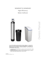
8QILOWHUHG:DWHU%\SDVV
/RRS&XW&DSSHG
*URXQG6WUDS5HTXLUHG%HFDXVH
RI%UHDNLQ&RQWLQXLW\
)LOWHUHG:DWHU/LQHLQ+RPH
Fig. 1.
WARNING
If the ground from the electrical panel or breaker box to the
water meter or underground copper pipe is tied to the copper
water lines and these lines are cut during installation of the
bypass valve and/or poly pipe, an approved grounding strap
must be used between the two lines that have been cut in
order to maintain continuity. The length of the grounding
strap will depend upon the number of units being installed
and/or the amount of copper pipe being
replaced with plastic pipe.
See Figure 1.
NOTE
Use of a competent installer or plumbing professional to
ensure this product is installed in accordance with local
plumbing codes is recommended. Canature is not liable for any
non-compliance with local requirements.
MECHANICAL
Do NOT use petroleum-based lubricants such as petroleum jelly, oils or hydrocarbon based lubricants. Use only 100% silicone lubricants (packet Part
#92360 provided in parts kit). All plastic connections should be hand tightened only. Thread tape may be used on connections that do not use an
O-ring seal.
Do NOT use pliers or pipe wrenches except when indicated by nut shape, e.g., pipe adapters. All plumbing must be completed according to local
codes. Soldering connections should be done before connecting any pieces to the pipe as excessive heat can damage them.
Softener resins will degrade in the presence of chlorine or chloramines above one (1) ppm. If you have anything in excess of this amount, you will
experience reduced life of the resin. Pre-carbon filtration may be required ahead of the water softener to reduce chlorine/chloramine levels
TOOLS REQUIRED FOR INSTALLATION
Two adjustable wrenches.
Additional tools may be required if modication to home plumbing is required.
Plastic inlet and outlet ttings are included with the softener. To maintain full valve ow, use of ¾” or 1” [1.9 cm or 2.54 cm] pipes to
and from the softener. You should maintain the same or larger pipe size as the water supply pipe to the softener inlet and outlet.
Use copper, brass, or PEX pipes and ttings.
Some codes may also allow PVC plastic pipe.
5/8” [15.8 mm] Outside Diameter drain line is needed for the valve drain.
Drain line tubing may be needed for the optional brine tank overow tting.
BEFORE INSTALLATION
Make sure you have a copy of your most recent water test results. If your water has not been tested previously, your professional installer can obtain
a water sample bottle to be sent to one of our facilities for a free analysis. It is important that this product not be installed until you have
this information.
In all cases where metal pipe was originally used and is later interrupted by poly pipe, or the Noryl bypass valve, an approved ground clamp with
physical separation and no less than #6 copper conductor must be used for continuity, to maintain proper metallic pipe bonding.

8 9
Plug
the
Riser
Tubes
The riser
(distributor)
remains inside
the tank
seated in the
depression at
the bottom
1. Temporarily plug the open end at the top
of the riser (distribution) tubes with tape.
2. Ensure the bottom of the riser tube remains
seated in the depression at the bottom of
the tank. Fill tank one-quarter full with
water to protect the distribution tube
during gravel installation.
3. Fill the gravel support bed rst.
A large funnel makes lling the
tank much easier. Order part #99003
separately for your own funnel.
Slowly add the gravel. Depending on
the type of system, add the resin, or
media next.
Support Bed
Gravel
Media
MANDATORY
Wear a Dust Mask.
Airborne particles could pose
potential health risks.
PREPARATIONS
MEDIA INSTALLATION (WHEN NECESSARY)
When larger units cannot be loaded due to weight restrictions, media will be shipped
pre-measured in separate containers. Follow the steps below for proper media loading.
NOTE
If severe loss in water pressure is observed when the softener
unit is initially placed in service, the softener tank may have
been laid on its side during transit. If this occurs, backwash the
softener to ‘reclassify’ the media.

10
D-Tube
Unscrew Spill Cap
Internal O-ring
Tank Seal O-ring
4. Apply the supplied lubricant (part #92360) to the internal O-ring at the bottom of the control valves.
Apply lubricant to the larger O-ring on the bottom of the valve that seals with the tank threads.
5. Remove the tape from the top of the riser tube. Carefully position the valve over the riser tube, inserting riser into the internal O-ring.
Turn the valve clockwise into the threads of the tank until secure.
PREPARATIONS (CONTINUED)
NOTICE
Make sure the quick connect power cord is not yet
connected to prevent the cord getting caught between
the threads of the tank and the valve.
NOTICE
Do NOT use petroleum-based
lubricants as they will cause
swelling of the O-ring seals.

10 11
2. Insert the brine well assembly inside and below the grid plate.
1. Attach the three brine grid legs to grid plate. The legs will snap on
to the tabs of the salt plate making a “clicking” sound. Please note,
some models will have extensions that are intended to be used as
well.
4. Take the brine tube and insert the nut
and plastic sleeve as shown below.
5. Insert the tube in the oat assembly
elbow and hand-tighten the nut.
In many cases the brine line already
comes installed from the factory.
Leave the other end of the brine
line tube inside the brine tank.
6. For installation of brine tank at the installation site, pull
the other end of the brine tube from the hole on the
brine tank. The completed assembly is below.
3. Place the brine grid with the brine well inside the brine tank such
that the nut tting faces the hole on the brine tank. Then press the
grid evenly inside the brine tank until the brine grid legs and the
brine well, as an assembly, touch the bottom of the brine tank.
The hole in the brine
tank should line up with
the brine line as shown
IMPORTANT: IN ROUND BRINE TANK, IT IS
IMPORTANT TO ALIGN THE HANDLE TO THE
BRINE WELL AS SHOWN.
Insert Sleeve
To assemble the brine tank, (some tanks may be square)
follow these steps:
PREPARATIONS (CONTINUED)
BRINE TANK ASSEMBLY

12
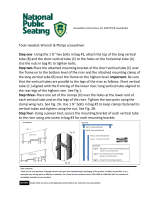
OUTLET
OUTLET
UNIT #1
LEAD VALVE
UNIT #1
LEAD VALVE
UNIT #2
FOLLOWER
VALVE
UNIT #2
FOLLOWER
VALVE
INLET
INLET
PLANNING YOUR INSTALLATION
Select the location for your softener tank with care. Various conditions that contribute to
proper location include:
1. All installation procedures must conform to local or regional plumbing codes. Canature is not liable for any non-compliance with local
requirements
2. Outside taps used to water lawns and gardens should be isolated from the water line required to supply untreated water
to the inlet of the water softener – a separate (new) line may be needed.
3. Where required by local plumbing codes, a check valve may need to be installed. Canature is not liable for any non-compliance with local
requirements
4. Locate softener as close as possible to the water supply source.
5. Locate softener as close as possible to a floor or laundry tub drain and a 120 volt AC electrical outlet.
6. Softeners should be located before the water heater on the supply line. If closer than three (3) metres [10 feet], install
a check valve in accordance with local plumbing codes.
7. Do NOT install a softener in a location where freezing temperatures occur. Freezing may cause permanent damage to
this type of equipment and will void the factory warranty. Freezing could also result in flooding and / or property loss and damage.
8. Allow sufficient space around the unit for easy servicing.
9. Keep the softener out of direct sunlight.
*NOTE
Check local plumbing codes requirements for use of
check valve(s), back-flow prevention,
or vacuum breakers. Canature is not liable for any
non-compliance with local requirements.
WATER SOFTENER INSTALLATION LAYOUT
CONFIGURATIONS
The connections for the unit can be turned up or down. Pay special attention to the figures below for the placement of the LEAD and FOLLOWER
valves as well as the configuration of the BYPASS / METER locations.

12 13
Water Pipe Inlet Water Pipe Outlet
Bypass
Brine Tank
Brine Valve
Connector Detail
Drain Elbow
Assembly
T-connection
3/8” Brine Tube
5/8” Drain Line
5/8” Overow Line (Optional)
Floor Drain
Optional Pipes
Fixed Structure
Brine Valve
Connector
Detail
Laundry Drain
AC 120V/10A
Current Protect Socket
PLANNING YOUR INSTALLATION (CONTINUED)
WATER SOFTENER INSTALLATION

14
NOTE
The waste connections or drain outlet shall be
designed and constructed to provide for connection to
the sanitary waste system through an air-gap of 2 pipe
diameters or 1” [25.4 mm] whichever is larger.
CAUTION
Never insert drain line directly into a drain, sewer line,
or trap. Always allow an air-gap between the drain
line and the wastewater to prevent the possibility of
sewage being back-siphoned into the softener.
Fig. 2.
Bypass
INSTALLATION STEPS
TO BEGIN YOUR INSTALLATION:
1. Make sure the bypass is attached securely to the lead valve & follower valve via the pipe connections as shown, See Fig. 2.
2. Apply thread tape to threaded connections straight or elbow plumbing adaptors
3. Apply the supplied lubricant (#92360) to the O-rings of the fittings.
4. Connect the supplied straight or elbow plumbing adaptors to the bypass with red clips.
5. Connect the inlet and outlet of the water softener to the plumbing of the house.
6. For the drain line connection; attach a 1/2” [12.7 mm] Inside
Diameter (ID), 5/8” [15.875 mm] Outside Diameter (OD) drain
hose to the drain line fitting.
a. Run the drain line to a floor or laundry drain.
b. Complete any necessary plumbing to maintain a proper air gap.
NOTICE
Any solder joints near the valve must be done before
connecting any piping to the valve. Failure to do
this could cause damage to the valve.
NOTICE
Do NOT use pipe thread compound as it may attack the
material in the valve body.
NOTICE
Failure to leave enough distance could cause damage
to the valve. Always leave at least 6” [152 mm]
between the valve and joints when soldering pipes
that are connected to the valve.

14 15
Fig. 3.
Brine tube
stiffener
T-Connection
Follower
valve
Lead valve
To brine tank
MANUAL WATER BYPASS
In case of an emergency, or to perform softener maintenance, you can
isolate your water softener from the water supply using the bypass valve
located at the back of the control.
In normal operation the bypass is OPEN with the ON/OFF knobs in line
with the INLET and OUTLET pipes, i.e., the black marks in the vertical
position. See SERVICE below.
To isolate the softener, simply rotate the knobs as indicated to the CLOSE
position until they lock. You can continue to use your water related
fixtures as the water supply is bypassing the softener. However, the
water you use will be untreated.
To resume treated service, OPEN the bypass valve by rotating the knobs
back to the SERVICE position.
NOTE
Please make sure bypass knobs are completely open
otherwise the untreated water may enter
through the valve.
SERVICE
INLETOUTLET INLETOUTLET
BYPASS
INSTALLATION STEPS (CONTINUED)
7. Attach the brine line from brine tank to brine line fitting on two control valves (lead valve & follower valve)
linking the two valves via the T-Connector. Install the tube stiffener into the end of the brine line before
attaching it to the brine line fitting on the control valves See Fig. 3.
8. Using the included Allen key, place the unit in the bypass position.
a. Slowly turn the main water supply ON.
b. At the nearest cold treated water tap, remove the tap screen, OPEN the tap and let
water run a few minutes or until the system is free of any air or foreign material
resulting from the plumbing work.
9. Make sure there are no leaks in the plumbing system before proceeding. Shut the water tap OFF when the water runs clean.
NOTE
If the tap has a screen, it should be removed to
allow debris to flush out of the plumbing.

16
MANDATORY
Do NOT use an outlet that is controlled by
a light switch.
UNDERSTAND THE SCREEN & KEYPAD CONFIGURATION
Keypad Legend – the terminology used on the conrol valve label may vary by model. For
the purpose of programming, this manual will use numbers associated with each button
position as shown on right:
The control valve is controlled with simple, user-friendly electronics, displayed on an LCD screen.
CONNECT THE TRANSFORMER
Connect the transformer to the unit by plugging the 12 volt transformer into a 120 VAC 60 Hz outlet.
When the power is connected, the screen will show the following information in sequence:
MAIN DISPLAY
The main display will pause on the Date and Time page for 5 seconds. Then it will continually scroll through all of the system diagnostic display
pages. To manually scroll through the diagnostics, press the down or up key. To reset the TOTAL REGENS, TOTAL GALLONS OVER RUN TOTAL, or PEAK
flow rates, press and hold the MANUAL REGEN key the value changes to zero.
PARAMETER DESCRIPTION
JULY/17/2023 8:30 PM Month, Day, Year, Time
U1 ONLINE TOTAL 1500 GAL The current status of Unit #1 (ONLINE or STANDBY). The total capacity of Unit #1.
U1 ONLINE REMAIN 1500 GAL The current status of Unit #1 (ONLINE or STANDBY). The remaining capacity of Unit #1.
U2 STANDBY TOTAL 1500 GAL The current status of Unit #2 (ONLINE or STANDBY). The total capacity of Unit #1.
U2 STANDBY REMAIN 1500 GAL The current status of Unit #2 (ONLINE or STANDBY). The remaining capacity of Unit #1.
LAST REGEN U1 9/24/23 The date of Unit #1 last regeneration.
LAST REGEN U2 9/24/23 The date of Unit #2 last regeneration.
TOTAL REGENS U1 999 The total number of Unit #1 regenerations.
TOTAL REGENS U1 999 The total number of Unit #2 regenerations.
TOTAL GALLONS U1 001590 GAL The total amount of gallons treated by Unit #1.
TOTAL GALLONS U2 001590 GAL The total amount of gallons treated by Unit #2.
CURRENT 1.5 GPM PEAK 6.5 GPM The current ow rate and the peak ow rate since the last regeneration.
REFILL TIME 12:00 The rell time.
VALVE MODE SOFTENER UF Regeneration mode of operation.

16 17
PRESS SETTINGS KEY
3 SEC TO UNLOCK
1. Press any button to start. The display
may read PRESS SETTINGS KEY 3
SEC TO UNLOCK if left untouched for
several minutes.
2. To unlock, press button one (1) and
hold for three (3)seconds. The display
will beep confirming unlock.
JAN/09/2023
12:15AM
MANUAL REGEN
U1 IMMEDIATELY
3. Press and hold button two (2) to
start Manual Regeneration process.
U1 BACKWASH
10:00 REMAIN
6. For Upflow valve press button two
(2) to manually advance to backwash
position. Downflow valves will
automatically start in backwash position.
4. Press button three (3) or four (4),
choose U1 or U2.
5. Press button two (2) to start a
regeneration cycle.
MANDATORY
Be sure to open the bypass inlet very slowly. Do
NOT FULLY open the bypass inlet until there is a
steady stream of water at the drain as this will
result in media being expelled from the unit
START-UP INSTRUCTIONS
Now that your water softener is plumbed into position it is time to start up and program the unit.
STEP 1. ADD WATER TO BRINE TANK
1. Open the brine tank salt lid and fill with water until there is approximately 1” [25.4 mm] of water above
the grid plate.
2. If there is no grid plate, fill the tank with 3” [75 mm] of water.
Do NOT add salt to the brine tank at this time.
NOTE
If severe loss in water pressure is ob-
served when the softener unit is initially
placed in service, the softener tank may
have been laid on its side during transit.
If this occurs, backwash the softener to
‘reclassify’ the media.
STEP 2. PURGE AIR FROM THE UNIT
7. Open the bypass inlet very slowly until there is a steady stream of
water at the drain. Opening the bypass inlet too quickly could result in
resin being expelled from the unit and into the plumbing lines. With the
valve in the backwash position the unit will purge air from the system,
sending it to the drain.
8. With the bypass inlet now fully open, let the system run until all the air is purged
and there is a steady stream of water at the drain.
9. Repeat steps two (2) to six (6) to purge the U2 tank of air. Press button two (2) to advance to the refill position and allow the unit to refill
the brine tank to 1” [25.4 mm] above the grid board – this may require manually advancing the unit through its cycles more than once.
Alternatively, you can press and hold button 2 (two) to advance to the service position and manually add the required amount of water
as described in step 1.
10. Allow the unit to return to the SERVICE position.
11. Slowly open the bypass OUTLET knob until fully open.

18
START-UP INSTRUCTIONS (CONTINUED)
STEP 3. PROGRAM SETTINGS
This unit is factory set for the correct size. You are required to program the date, the time of day, the number of people living in the home and the
correct hardness setting. Please review Compensated Hardness Calculation before entering the hardness number from your water analysis.
Compensated Hardness Calculation:
__ ppm Iron x 4 = __ grains of hardness
__ ppm Manganese x 8 = __ grains of hardness
These numbers can be found on your water analysis report, and the equivalent grains of hardness should be added to your total hardness number.
The new sum of these numbers is the hardness to be entered during the programming.
Example
Our water analysis states that our hardness is 15 gpg.
To this we add;
Iron = 0.5 ppm x 4= 2.0 gpg
Manganese = 0.3 x 8= 2.4 gpg which we round-up (always) to 3.0 gpg
We use the following hardness equation to derive our total hardness number.
Hardness = 15 gpg + 2.0 (now called compensated iron) + 3.0 (compensated manganese) = 20 gpg.
Enter 20 for total hardness when programming.

18 19
START-UP INSTRUCTIONS (CONTINUED)
CURRENT TIME
12:15AM
CURRENT TIME
12:15AM
CURRENT TIME
12:15AM
CURRENT TIME
12:15AM
5. Press button one (1) once to
highlight the next value.
7. Press button one (1) once
to highlight the next value.
6. Now press button three
(3) or four (4) to change the
minute value to current time.
4. Now press button three
(3) or four (4) to change the
hour value to current time.
PRESS SETTINGS KEY
3 SEC TO UNLOCK
AUG/30/2019
12:15AM
1. The display may read “PRESS SETTINGS
KEY”. Press button one (1) for three
seconds (3) to unlock.
2. After three (3) seconds, the display will
beep confirming unlock.
3. Press and hold button one (1)
for three seconds (3) until you
hear a beep. This will unlock the
SETTINGS menu.
YEAR
2022
CURRENT TIME
12:15PM
YEAR
2023
9. Press button one (1) once to
highlight the value.
8. Now press button three
(3) or four (4) to change the
AM/PM value to current time.
10. Now press button three
(3) or four (4) to change the
YEAR value to current year.
MONTH
Feb
DAY
12
MONTH
Mar
11. Press button one (1) once
to highlight the current
month.
13. Press button one (1) once
to highlight DAY.
12. Now press button three
(3) or four (4) to change
the MONTH value to desired
month.
STEP 3. PROGRAM SETTINGS

20
DAY
19
SET HARDNESS
25 GRAINS
SET HARDNESS
15 GRAINS
15. Press button one (1) once
to highlight SET HARDNESS
value.
16. Now press button three (3) or four (4)
to change HARDNESS value.
N SALT SETTING
STANDARD
17. Press button one (1) once to
highlight SALT SETTING.
WATER SOURCE
MUNICIPAL
18. Press button one (1) once to
highlight WATER SOURCE.
WATER SOURCE
WELL/OTHER
19. Now press button three (3) or four
(4) key to change WATER SOURCE
value. For problem water set to WELL/
OTHER. For clean, city water choose
MUNICIPAL.
TRIP POINT
OFF
TRIP POINT
U5 T30S D3 T01M
20. The TRIP POINT is
factory set to OFF.
21. Press button one (1) once to
highlight value. Press button
three (3) or four (4) to enter Trip
Point. Press button one (1) to
change settings. Press button
three (3) or four (4) to select
setting, press button one (1) to
accept and advance to next setting.
PROGRAMING
COMPLETE
22. Press button one (1) once to
COMPLETE PROGRAMING.
Trip Point Explanation:
The 85TA controllers will operate with one tank in service and the second tank off-line for regeneration or ready in standby.
Based on peak flow water usage, the trip points can be set accordingly.
EXAMPLE: U5 T30S D3 T01M
Upper flow is set for 5GPM / for Time 30 Seconds / flow drops Down to 3gpm for a Total of 1 Minute. When the trip
points are set, should the flow rate exceed five (5)GPM for more than thirty (30) seconds, the controller will bring both tanks
into service to provide maximum service flow rate when it is needed. When the flow rate is less than three (3)GPM for one (1)
minute the second tank will come off line and enter standby. When the two valves are in service at the same time, the total
treated water will be divided by two (2) and subtracted from the capacity of each tank.
START-UP INSTRUCTIONS (CONTINUED)
STEP 3. PROGRAM HOUSEHOLD SETTINGS CONTINUED
NOTE
This product has had the salt setting factory programmed and locked for correct operation and efficiency. Do NOT adjust this setting
unless you have consulted your authorized dealer or technical services. Unauthorized adjustment will result in unsatisfactory
performance of this product.
/