Open the door. Slip the multi-blade bug sweep (F) onto the bottom of
the door. Hold sweep in place and close the door. Allow the sweep to
fall and set rested on the threshold plate (E). Note: Be sure there is not
a gap between the sweep and the threshold plate, and that the sweep
is centered on the bottom of the door. Use 1/8" drill bit to pre-drill the
two outer holes for mounting screws. Attach the sweep to the bottom
of the door, by the two outer holes, using the provided screws (J). Test
that the door opens and closes freely. If not, loosen the screws and
make necessary adjustments. Retighten screws and test again. Repeat
until successful. Pre-drill remaining holes and install the rest of the
provided screws (J).
8
5
Place the top header jamb (C) above the door and between the two
side jambs. Spacing should be equal, from left to right, above the door
and be similar to spacing determined in Step 3. Mark the location of
the mounting holes. Set the jamb aside and, where marked, pre-drill
3/16" holes. Return jamb to position and fasten to house using the
provided one-way screws (G).
6
Place bottom bar (D) beneath the side jambs. Both ends should reach
the outer edge of the side jambs. Hold in place and use 5/32" drill bit
to pre-drill holes for mounting screws. Attach bottom bar to each side
jamb using the provided screws (H).
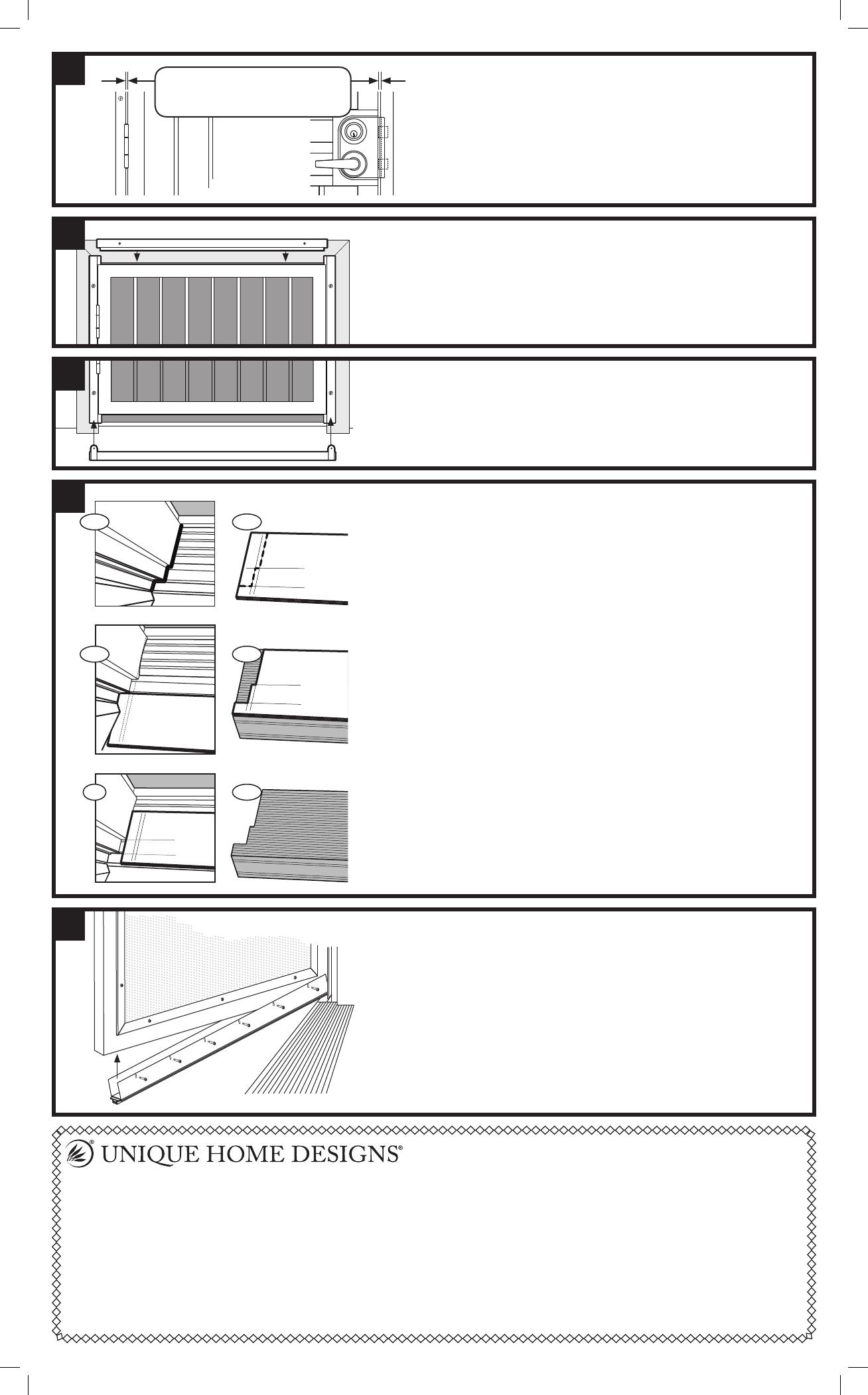
7
The contour of door framing varies (6a) making it necessary to cut
the threshold plate (E) to fit. We recommend cutting a cardboard
template to fit the opening first to avoid incorrectly cutting
the threshold plate.
Cut a piece of cardboard 36" x 6" (same size as top of threshold
plate). Lay template on top of the bottom bar and push into existing
threshold as far as it will go. Using a straight edge, mark the template
at the various widths of your existing molding and trim at both ends
(6b). Move template so that front edge is flush to the front edge of
bottom bar (it is okay to bend to allow to fit the shortest width between
your molding and trim). Mark at the various corners of your existing
molding and trim (6c). Using a box knife cut template to shape of
molding and trim revealed by the markings (6d). Test fit the template.
(It should lay across the bottom bar with the front edge flush with the
front edge of the bottom bar and fit in and around the corners of the
existing molding and trim.)
Once you have created a good fitting template, use the template
to mark the threshold plate (6e). Using tin-snips (or hacksaw) cut
threshold plate to match the shape of template (6f). Postition threshold
plate to extend across the bottom bar and into the existing threshold.
Use 1/8" drill bit to pre-drill holes for mounting screws. Attach
threshold plate to existing threshold using the provided screws (I).
6a
6d
6b
6e
6c
6f
4
Align the lock holes in the lock-side jamb with the lock bolts
extended. Maintain a space between door (A) and the
lock-side jamb (B) equal or similar to the space between
the door and hinge-side jamb, from top to bottom. Making
sure the lock-side jamb is plumb, mark the location of the
mounting holes. Set the jamb aside and, where marked,
pre-drill 3/16" holes. Return jamb to position and fasten to
house using the provided one-way screws (G).
Gap between door and both
side jambs should appear equal
(minimum 1/8", up to 1/4")
Hinge side
Lock side
Premium Steel Security Door Warranty
Your premium steel security door is warranted against manufacturing defects of the welded frame, pickets, and lock box for as long as you own
the home upon which the door is properly installed. If structural defects occur in these areas we will, at our discretion, repair or replace the door.
Replacement items may vary in style due to changes in suppliers and product. In addition, the paint finish is warranted not to blister, crack, or fade for
one year from the purchase date. Damage due to rust is excluded from this warranty. Screens, glass and hardware are also excluded from this warranty.
This warranty does not cover damage caused by vandals, break-ins, or attempted break-ins. This warranty is voided if the product is modified in
any way. Any problem caused by abuse, misuse, failure to maintain warranted item properly, adjustments due to settling of the structure that the
product is mounted on, or acts of God, are not covered. Unique Home Designs assumes no responsibility for labor costs of any kind for removal,
replacement of parts, repairs, or reinstallation.
To make a claim under this warranty, send a brief written description of the problem, a picture of the problem, proof of purchase, and your
contact information to: Unique Home Designs, 973 N. Colorado Street, Gilbert AZ. 85233 Attn: Warranty Claims

