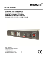
HQ Power KRYSTAL RGY260 Specification

Category
Stroboscopes & disco lights
Type
Specification
11
H
o
C
o
M
o
M
o
Di
e
/08/2011
o
w to turn
t
o
ntroller li
n
o
difier la li
g
o
dificar la l
e
Controll
e
VDP
2
t
he control
n
e van 3-pi
n
g
ne du con
t
ínea del c
o
e
r-Linie vo
n
2
301RGVL
D
ler line fro
m
n
naar 5-pi
t
rôleur de
3
o
ntrolador
d
n
3-Pin nac
h
D
10 - VDP2
6
m
3-pins i
n
n aanpass
e
3
broches
e
d
e 3 polos
y
h
5-Pin an
z
6
01RGYLD
1
2
n
to 5-pins
(
e
n (stekke
r
e
n 5 broch
e
y
5 polos (
c
z
upassen (
S
1
0 - VDP3
8
(
plug and s
r
en contac
t
e
s (fiche e
t
c
onector y
S
tecker un
d
8
01RGVLD
1
termi
n
eindweers
t
résistan
c
termin
a
termin
a
Terminie
r
ocket).
t
).
t
contact).
contacto).
d
Kontakt)
.
1
0
n
ator
t
and
c
e de
a
ison
a
ción
r
ung
.
©Vellema
n
n
nv
11
1
.
T
o
I
m
Th
If
t
Th
op
As
2
.
/08/2011
.
Introd
u
o
all reside
n
m
portant e
n
This
har
m
shou
distri
If in
ank you for
t
he device
w
e VDP230
1
erated in 3
m
sociation) s
t
VDP2
3
VDP3
8
VDP2
6
.
Safety
I
Be
Do
Ke
e
Un
p
Us
e
Wh
NE
V
ey
e
Do
Ke
e
VDP23
0
VDP38
0
VDP26
0
Damage ca
dealer will
n
A qualified
Do not swi
t
device agai
This device
qualified p
e
VDP
2
u
ction
n
ts of the
E
n
vironmen
t
symbol on t
h
m
the enviro
n
ld be taken
t
butor or to
a
doubt, co
n
choosing H
Q
w
as damage
d
1
RGVLD10,
m
odes: DM
X
t
andard mo
d
3
01RGVLD
1
8
01RGVLD
1
6
01RGYLD
1
I
nstruct
very careful
not touch t
h
e
p this devi
c
p
lug the ma
i
e
extreme c
a
en device is
V
ER point t
h
e
s or skin. B
not point t
h
e
p out of re
a
0
1RGVLD1
0
0
1RGVLD1
0
0
1RGYLD1
0
used by dis
r
n
ot accept r
e
technician s
t
ch the devi
c
nst damage
falls under
e
rson carry
o
2
301RGVL
D
E
uropean U
n
t
al informa
t
h
e device o
r
n
ment. Do n
t
o a speciali
a
local recy
c
n
tact your l
Q
-power! Pl
e
d
in transit,
VDP2601
R
X
/sound con
t
d
e. Each pro
j
1
0: 230mW
1
0: 380mW
1
0: 260mW
ions
during the
h
e device d
u
c
e away fro
m
i
ns lead bef
o
a
ution when
in use, do
N
h
e laser bea
urns and pe
h
e laser bea
m
a
ch of all chi
Th
e
AV
O
AP
E
0
0
0
r
egard of ce
r
e
sponsibilit
y
hould instal
l
c
e on imme
d
by leaving
i
protection c
o
ut the elec
t
D
10 - VDP2
6
Us
e
n
ion
t
ion about
t
r
the packag
ot dispose
o
zed compan
c
ling service
.
ocal waste
e
ase read th
do not insta
R
GYLD10 a
n
t
rolled, SD
c
j
ector has 1
RGV (Red
G
RGV (Red
G
RGY (Red
G
installation:
u
ring operati
m
rain and
m
o
re opening
the laser b
e
N
OT look d
m directly
o
rmanent ey
e
m
towards h
ldren.
e
arrow indi
c
O
ID EXPO
S
E
RTURE
r
tain guideli
n
y
for any en
s
l
and servic
e
d
iately after
i
t switched
o
lass I. It is
t
t
ric connecti
o
6
01RGYLD
1
3
e
r man
t
his produ
c
e indicates
t
o
f the unit (
o
y for recycli
.
Respect th
e
disposal a
e manual th
ll or use it a
n
d VDP380
1
c
ard mode o
0 DMX chan
G
reen Violet
)
G
reen Violet
)
G
reen) laser
touching li
v
on as the h
o
m
oisture.
the housing
e
am is turn
e
irectly or i
n
o
r via a refle
c
e
damage w
ighly explos
c
ates the las
S
URE - LAS
E
n
es in this
m
s
uing defect
s
e
this device
it has been
o
ff until it h
a
t
herefore es
s
o
n.
1
0 - VDP3
8
ual
c
t
t
hat disposa
o
r batteries)
ng. This de
v
e
local envi
r
uthorities.
oroughly be
nd contact
y
1
RGVLD10
r via PC – I
L
nels (6 in S
D
)
laser proje
c
)
laser proje
c
projector
v
e wires can
o
using heat
s
.
e
d on.
n
directly (
r
c
ting surfac
e
ill result.
ive gasses.
er aperture.
E
R RADIAT
m
anual is no
t
s
or proble
m
.
exposed to
c
a
s reached r
o
s
ential that
t
8
01RGVLD
1
l of the devi
as unsorte
d
v
ice should
b
r
onmental r
u
fore bringin
g
y
our dealer.
are laser pr
o
L
DA (Intern
a
D
card mod
e
c
tor
c
tor
cause life-t
h
s
up.
r
eflectance
e
towards o
t
ION IS EM
I
t
covered b
y
m
s.
c
hanges in
t
o
om temper
t
he device b
1
0
ce after its l
d
municipal
w
b
e returned
t
u
les.
g
this devic
e
o
jectors tha
t
a
tional Lase
r
e
).
h
reatening
e
) into the l
a
t
her people’
s
I
TTED FRO
y
the warran
t
emperature
ature.
e earthed.
H
©Vellema
n
ifecycle cou
l
w
aste; it
t
o your
e
into servic
e
t
can be
r
Display
e
lectroshock
s
a
ser beam
.
s
or animals
M THIS
ty and the
. Protect th
e
H
ave a
n
nv
l
d
e
.
s
.
.
e
VDP2301RGVLD10 - VDP2601RGYLD10 - VDP3801RGVLD10
11/08/2011 ©Velleman nv
4
Make sure that the available voltage does not exceed the voltage stated in the specifications of this manual.
Do not crimp the power cord and protect it against damage. Have an authorised dealer replace it if
necessary.
Disconnect the device from the mains to clean it or when it is not in use. Handle the power cord by the plug
only.
Keep the device away from splashing and dripping liquids. Never put objects filled with liquid on top of the
device.
Note that damage caused by user modifications to the device is not covered by the warranty.
Mechanical wear is not covered by warranty.
Keep the device away from children and unauthorised users.
3. General Guidelines
Refer to the Velleman® Service and Quality Warranty on the last pages of this manual.
Nor Velleman nv nor its dealers can be held responsible for any damage (extraordinary, incidental or
indirect) – of any nature (financial, physical…) arising from the possession, use or failure of this product.
This device is designed for professional use on stage, in discos, theatres, etc. The laser projector should
only be used indoors with an alternating current of max. 230VAC / 50Hz.
Lighting effects are not designed for permanent operation: regular operation breaks will prolong their lives.
Do not shake the device. Avoid brute force when installing or operating the device.
Select a location where the device is protected against extreme heat, dust and moisture.
Use an appropriate safety cable to fix the device (e.g. VDLSC7 or VDLSC8).
Familiarise yourself with the functions of the device before actually using it. Do not allow operation by
unqualified people. Any damage that may occur will most probably be due to unprofessional use of the
device.
Use the original packaging if the device is to be transported.
All modifications of the device are forbidden for safety reasons.
Only use the device for its intended purpose. All other uses may lead to short circuits, burns, electroshocks,
crash, etc. Using the device in an unauthorised way will void the warranty.
4. Mounting/connecting the device
Have the device installed by a qualified person, respecting EN 60598-2-17 and all other applicable norms.
The carrying construction must be able to support 10 times the weight of the device for 1 hour without
deforming.
The installation must always be secured with a secondary attachment e.g. a safety cable.
Never stand directly below the device when it is being mounted, removed or serviced. Have a qualified
technician check the device once a year and once before you bring it into service.
Install the device in a location with few passers-by that is inaccessible to unauthorised persons.
Overhead mounting requires extensive experience: calculating workload limits, determining the installation
material to be used… Have the material and the device itself checked regularly. Do not attempt to install the
device yourself if you lack these qualifications as improper installation may result in injuries.
Adjust the desired inclination angle via the mounting bracket and tighten the bracket screws.
Make sure there is no flammable material within a 0.5m radius of the device.
Have a qualified electrician carry out the electric connection.
Connect the device to the mains with the power plug. Do not connect it to a dimming pack.
The installation has to be approved by an expert before the device is taken into service.
For installations using DMX512:
Connection
Connect the provided XLR cable to the female 3-pin XLR output of your controller and the other side to
the male 3-pin XLR input of the laser projector [7]. Multiple laser projectors can be linked through serial
linking. The linking cable should be a two-core screened cable with XLR input and output connectors (see
page 2 for pin-out).
Chain with Termination
A DMX terminator is recommended for installations where the DMX cable has to run a long distance or is
in an electrically noisy environment (e.g. discos). The terminator prevents corruption of the digital control
signal by electrical noise. The DMX terminator is simply an XLR plug with a 120 resistor between pins 2
and 3, which is then plugged into the XLR output socket [8] of the last device in the chain (see page 2).
For installations using ILDA (PC mode) use following ILDA cable layout (DB-25F):
PIN signal name remarks
1 X+ -5V to +5V
2 Y+ -5V to +5V
5 Red+ 0V to 2.5V
6 Green+ 0V to 2.5V
14 X- Connected to ground
15 Y- Connected to ground
18 Red- Connected to ground
19 Green- Connected to ground
25 Ground Cable shield
11
5
.
Re
2
3
4
5
6
7
8
9
1
1
1
1
6
.
Re
6.
/08/2011
.
Descri
p
fer to the ill
1 MIC
2
VOLUM
E
3
READY
ERROR
4
FUNC S
E
5
SD CAR
6
MODE
S
7
DMX IN
8
DMX O
U
9
DIP SW
I
1
0 ILDA IN
1
1 ILDA T
H
1
2 ON/OF
F
1
3 AC IN
~
.
Use
f
er to the ill
The laser p
o Sound/
D
o SD card
o PC cont
r
Select the
d
1 Sou
n
Press the S
Use the DI
P
o Sound
/
auto an
d
o DMX c
o
DMX st
a
Star
t
All D
M
sign
a
cont
r
You
c
ever
y
Whe
n
parti
c
VDP
2
p
tion
ustrations o
E
DMX
DATA
E
LECT UP
D SLOT
S
WITCHES
U
T
I
TCH
H
RU
F
*
~
ustrations o
rojector can
D
MX controll
controlled
r
olled (via I
L
d
esired mod
n
d/DMX
c
OUND&DM
X
P
switch [9]
/
auto/slav
e
d
slave mod
e
Fu
n
sou
n
aut
o
slav
cou
n
o
ntrol mod
e
a
rt address (
addr
e
5
19
40
t
Address
S
M
X-controll
e
a
ls. This sta
r
r
oller.
c
an use the
s
y
device.
n
all devices
c
ular chann
e
2
301RGVL
D
n page 2 of
microph
volume
status L
SD card
slot for
S
select o
p
DMX in
p
DMX ou
t
set the
D
ILDA st
a
ILDA st
a
on/off k
e
AC inpu
t
n page 2 of
work in 3 d
ed
L
DA standar
d
e by pressi
n
c
ontrolle
d
X
mode swit
c
to configur
e
e
mode: sw
i
e
.
n
ction
n
d mode (m
o
mode
e mode
n
tdown mod
e
: switch 10
max. 511).
e
ss
D
S
etting
e
d devices n
e
r
t address is
s
ame starti
n
have the s
a
e
l. In other
w
D
10 - VDP2
6
this manual
one
control
EDs for SD
c
controls
S
D card
p
erating mo
d
p
ut port (3 p
t
put port (3
D
MX addres
s
a
ndard inpu
t
a
ndard sign
a
e
y switch
t
110~240V
a
* depe
n
this manual
ifferent mo
d
d
)
n
g the corre
s
d
mode
c
h [6] to se
l
e
sound or
D
i
tch 10 mus
t
aster)
e*
* the la
must be se
t
Examples:
D
IP Switch
e
e
ed a digita
l
the channe
l
n
g address f
o
a
me addres
s
w
ords: chan
g
6
01RGYLD
1
5
.
c
ard mode
d
e
ins)
pins
s
t
a
l throughpu
a
c 50/60Hz
n
ding on th
e
.
d
es:
s
ponding m
o
l
ect Sound/
D
D
MX mode:
t
be set to t
h
ser projects
t
to the ON
p
e
s
l
start addr
e
l
number fr
o
o
r a whole
g
s
, all laser p
r
g
ing the set
t
1
0 - VDP3
8
t
(and fuse h
o
e
model an
a
o
de switch [
6
D
MX controll
h
e OFF posi
t
DIP Sw
a countdo
w
p
osition. Sw
i
s
w
e
ss so that t
h
o
m which th
e
g
roup of dev
i
r
ojectors wil
l
t
ings of one
8
01RGVLD
1
o
lder)
a
dditional o
n
6
].
ed mode.
t
ion. Switch
e
itches
w
n sequence
i
tches 1 thr
o
w
itch
1
2
3
4
5
6
7
8
9
h
e correct d
e
e
device sta
r
i
ces or ente
r
l
“listen” to
t
channel wil
l
1
0
n
/off switch
m
e
s 1 and 2 t
h
from 9 to 0
o
ugh 9 than
represe
n
1
2
4
8
16
32
64
128
256
e
vice respo
n
r
ts to
listen
r
an individ
u
t
he control
s
l
affect all d
e
©Vellema
n
m
ay be pre
s
h
an determi
n
.
determine
t
n
ts
n
ds to the
” to the DM
X
u
al one for
s
ignal on on
e
e
vices
n
nv
s
ent
n
e
t
he
X
e
VDP2301RGVLD10 - VDP2601RGYLD10 - VDP3801RGVLD10
11/08/2011 ©Velleman nv
6
simultaneously. If you set different addresses, each device will “listen” to a separate channel number.
Changing the settings of one channel will only affect the device in question.
In the case of the 10-channel laser projector, you will have to set the start address of the first laser
projector to 1, the second laser projector to 11 (10 + 1), the third to 21 (10 + 11) and so on.
DMX5 channel assignment
Channel DMX512
value
function
1 control mode
0--63 Sound control (channel 3~10 not used)
64--127 Auto mode (channel 3~10 not used)
128--191 DMX control
192--255 Auto mode
2 blanking & blackout
VDP2301RGVLD10
VDP3801RGVLD10
VDP2601RGYLD10
0--5 blackout blackout
6--10 white
red
11--15 red
16--25 yellow
green
21--25 green
26--30 cyan
yellow
31--35 blue
36--40 purple 36--105 single colour (auto)
41--110 single colour (auto) 106--175 tri-colour (auto)
111--180 multi-colour (auto) 176--245 tri-colour (move)
181--251 multi-colour (move) 246--255 bounded colour
251--255 bounded colour
3 pattern 0--255 124 patterns (0-255)
4 vertical move
0--127 manual vertical move
128--191 auto down, speed up accordingly
192--255 auto up, speed up accordingly
5 horizontal move
0-127 manual horizontal move
128--191 manual right, speed up accordingly
192-255 manual left, speed up accordingly
6 vertical roll
0--127 manual vertical rotation
128--255 auto vertical rotation, speed up accordingly
7 horizontal roll
0--127 manual horizontal rotation
128--255 auto horizontal rotation
8 rotation
0--127 manual rotation
128--191 auto clockwise rotation, speed up accordingly
192--255 auto anti-clockwise rotation, speed up accordingly
9 zoom in & out
0--85 from small to large, speed up accordingly
86--170 from large to small, speed up accordingly
171--255
large ←→ small, speed up accordingly
10 point draw 0--255 0=nil / 1~255=faint ~bright
6.2 SD Card controlled mode
Press the SD CARD mode switch [6] to select SD CARD controlled mode.
In SD CARD mode, a DMX address (and thus a controller) is still required.
SD card notes:
Only use high quality SD cards of well known brands to avoid reading errors.
Max. supported capacity = 2GB.
The card must be formatted as FAT16 file system. The card that comes with the device is already correctly
formatted.
Do not place files in sub-directories.
Do not place more than 260 files in the root directory.
File name length is limited to 8 characters (followed by the .ild extension).
5animated) files (shows) must be created using an appropriate ILDA software program (not included).
The root directory may contain 3 reserved files. Do not remove these files:
o CONFIG.DAT: contains setting information for the laser projector. See further for instructions on creating
and modifying this file.
o FLASHMP.BIN: control program for firmware updates
VDP2301RGVLD10 - VDP2601RGYLD10 - VDP3801RGVLD10
11/08/2011 ©Velleman nv
7
o FWUPxxx.BIN: specific update (xxx=update number). This file is removed automatically when the update
procedure is completed.
Definitions:
A show contains a number of frames which are played (projected) in sequence.
Each frame is drawn by a laser as a series of points. The time between the points determine the
smoothness of the frame. The overall speed is expressed in Kilo points per second (Kpps). When this value
is set too low, the frame will not be completely visible or flickers.
Note: setting the speed at max. (= 20Kpps) all the time puts a lot of stress on the internal moving parts of
the projector.
The time between to consecutive frames (= the speed of the animation) is set by the frame repeat
parameter. A low (DMX-) value will produce a low animation speed.
Note: running the animations at max. speed all the time puts a lot of stress on the internal moving parts of
the projector.
When the laser has to draw two non-consecutive points, it will switch off for a brief period of time, the so
called blank shift. A low value will switch off the laser immediately at one point and switch it on again in
the next; increasing the value will delay laser switching.
DMX channels:
In SD CARD mode, the laser projector becomes a 16-channel DMX device. However, only 9 of these
channels can be controlled, the other ones are defined by the projected animation.
Use the output of the DMX-controller (not incl.) to control the channels. Refer to CONFIG.DAT below for an
overview of the DMX channels.
SD card controls:
There are 3 buttons to control the SD card mode:
o FUNC [A]
Select the parameter to change:
“Adr” = DMX address (1~512)
“Int” = max. colour/laser output intensity (0~99).
“Ort” = orientation of the projection (0~7)
0 normal 4 X and Y swapped
1 X inverted 5 X and Y swapped; X inverted
2 Y inverted 6 X and Y swapped; Y inverted
3 X and Y inverted 7 X and Y swapped, X and Y inverted
o SEL [B]
Press this button to see the current setting of “Adr”, “Int” or “Ort”.
Press again to edit the setting. The right digit starts blinking and can be changed using the UP button.
Press SEL again to edit the middle digit; press again to edit the left digit. Press FUNC to store and exit.
o UP [C]
Press this button to increase the value of the blinking digit (0~9).
Note: the LCD will return to normal display after 10s of inactivity
Status LEDs:
Refer to the table below for the meaning of the status LEDs.
READY
(green)
DMX
(green)
ERROR
(red)
DATA
(yellow)
X no MMC/SD card present
X X no FAT16 file system found
X X X data error while reading card
X X file not found or invalid
X X no DMX signal
X X laser projector ready
Note: X = ON
Not every error will cause the laser output to stop. This will only be the case when access or read/write
errors on the memory card occur or files are corrupted.
CONFIG.DAT:
The file CONFIG.DAT contains configuration information for the laser projector. It can be created and
modified by using the software tool EditConfig.exe which is shipped with every laser projector.
Insert the included SD card in a suitable PC, locate EditConfig.exe and double click it to open the
configuration file:
VDP2301RGVLD10 - VDP2601RGYLD10 - VDP3801RGVLD10
11/08/2011 ©Velleman nv
8
To start a new configuration, select New Config; to adjust and existing configuration, click Load Config.
Select the desired file in the pop-up window.
Global data:
Set the DMX base address of the laser projector between 1 and 511.
When multiple laser projectors are linked, and they must produce the same output, their addresses must
be set to the same value and their CONFIG.DAT files must be identical.
If they are controlled individually, their addresses must be separated by 16 as each device needs 16 DMX
channels. So the first should be at 1, the second at 17 the third on 33 and so on.
DMX-Channels 1-16:
Define the DMX channel numbers to control the laser animation. Every function must have a unique
channel number (1~16).
Except for the first two parameter (show select L and show select H) all parameters can be set to a
fixed value by checking the none-box and entering the desired value in the dropdown box behind the
parameter or in the showtable below the parameters. In this case, the parameter can not be changed via
DMX anymore.
The Show Select H parameter can be set to none by checking the checkbox. By doing this, only the first
16 files in the showtable are accessible.
show select L Select one of the first 16 shows on the card (including pause). Each show occupies
16 DMX values.
show select H Select one of the 16 banks of shows, each bank containing 16 shows (total=256
shows). A bank uses 16 DMX values.
Speed Kpps Set the frame drawing speed (Kpps).
Note: this setting might influence the blank shift setting.
Frame repeat Control the animation speed.
projection size Change the size of the projection (see important note below).
Changing the size too fast will result in a ‘jumping’ display.
offset X 0 = maximum negative offset
128 = centre position
255 = maximum positive offset
Note: projected display might ‘jump’ due to the slow DMX signal rate
offset Y 0 = maximum negative offset
128 = centre position
255 = maximum positive offset
Note: projected display might ‘jump’ due to the slow DMX signal rate
Blank shift Control the laser off-time between non-consecutive points of the frame.
Intensity Control the intensity of the laser output.
VDP2301RGVLD10 - VDP2601RGYLD10 - VDP3801RGVLD10
11/08/2011 ©Velleman nv
9
IMPORTANT NOTE
Setting the projection size to zero can cause a standing laser beam. This is a hazardous
condition that must be avoided at all times.
Showtable:
Note: the show in the first data entry field, DMX value 0, is displayed when the laser projector is paused
or when an empty data location (no filename provided) is opened. For safety reasons it is strongly
advised to leave this empty.
Enter up to 256 shows into the filename-fields. Click on a filename field to open an explorer dialog box.
Select the desired .ild file.
Note: the .ild file must be on the SD card.
Notes:
Every show occupies 16 DMX values. The relationship between DMX control and DMX Value (=
filename) is given in the table below:
Showselect H
0-
15
16-
31
32-
47
48-
63
64-
79
80-
95
96-
111
112-
127
128-
143
144-
159
160-
175
176-
191
192-
207
208-
223
224-
239
240-
255
Showselect L
240-255 15 31 47 63 79 95 111 127 143 159 175 191 207 223 239 255
224-239 14 30 46 62 78 94 110 126 142 158 174 190 206 222 238 254
208-223 13 29 45 61 77 93 109 125 141 157 173 189 205 221 237 253
192-207 12 28 44 60 76 92 108 124 140 156 172 188 204 220 236 252
176-191 11 27 43 59 75 91 107 123 139 155 171 187 203 219 235 251
160-175 10 26 42 58 74 90 106 122 138 154 170 186 202 218 234 250
144-159 9 25 41 57 73 89 105 121 137 153 169 185 201 217 233 249
128-143 8 24 40 56 72 88 104 120 136 152 168 184 200 216 232 248
112-127 7 23 39 55 71 87 103 119 135 151 167 183 199 215 231 247
96-111 6 22 38 54 70 86 102 118 134 150 166 182 198 214 230 246
80-95 5 21 37 53 69 85 101 117 133 149 165 181 197 213 229 245
64-79 4 20 36 52 68 84 100 116 132 148 164 180 196 212 228 244
48-63 3 19 35 51 67 83 99 115 131 147 163 179 195 211 227 243
32-47 2 18 34 50 66 82 98 114 130 146 162 178 194 210 226 242
16-31 1 17 33 49 65 81 97 113 129 145 161 177 193 209 225 241
0-15 0 16 32 48 64 80 96 112 128 144 160 176 192 208 224 240
Set the desired frame drawing speed, framerepeat and display mode by clicking on either one of those
fields:
Displaymode
oneshot/complete The show is shown 1 time completely. It can not be interrupted. When
finished, the projector goes into pause mode.
oneshot/interruptable The show is shown 1 time completely. It can be interrupted via DMX. When
finished, the projector goes into pause mode.
loop/complete The show is shown in a continuous loop. It can only be interrupted at the
end of the show.
loop/interruptable The show is shown in a continuous loop. It can be interrupted at any time
via DMX.
VDP2301RGVLD10 - VDP2601RGYLD10 - VDP3801RGVLD10
11/08/2011 ©Velleman nv
10
Click on No File to remove the file from the list.
Click OK to save the settings.
When desired, a list of all DMX settings can be printed by clicking the Print button.
To save the configuration, click on Save Config. The file must be saved as CONFIG.DAT as this is the
file that will be loaded automatically by the laser projector.
Place the SD card back in the laser projector and switch the projector on. Make sure the SD CARD mode
switch [6] is pressed and the correct DMX address is set via the SD card controls.
6.3 PC controlled mode
The PC controlled mode uses the ILDA (International Laser Display Association) standard for control signal
and file formats. The laser projector must be connected to a suitable PC running appropriate software (e.g.
Pangolin, Mamba, Phoenix…). Refer to §5 for the cable layout of the ILDA cable. More on the ILDA standard
can be found on http://www.laserist.org/standards.htm
.
IMPORTANT NOTE
Make sure to set the scan rate in the software equal to or lower than the actual scan rate of
the laser projector. Setting the scan rate too high may damage the laser projector; this
damage is not covered by the warranty.
Press the PC MODE switch [6] to select PC mode.
In this mode, the laser projector will receive its instructions and shows via the ILDA input port [10].
Multiple laser projectors can be linked via the ILDA THRU port [9].
7. Cleaning and Maintenance
All screws should be tightened and free of corrosion.
The housing, visible parts, mounting supports and the installation location (e.g. ceiling, suspension,
trussing) should not be deformed, modified or tampered with e.g. do not drill extra holes in mounting
supports, do not change the location of the connections.
Moving mechanic parts must not show any signs of wear and tear.
The electric power supply cables must not show any damage. Have a qualified technician maintain the
device.
Disconnect the device from the mains prior to maintenance activities.
Wipe the device regularly with a moist, lint-free cloth. Do not use alcohol or solvents.
There are no user-serviceable parts apart from the fuse.
Contact your dealer for spare parts if necessary.
8. Technical specifications
VDP2301RGVLD10 VDP3801RGVLD10 VDP2601RGYLD10
Laser colour
/power
red 663nm/160mW 665nm/215mW 662nm/200mW
green 533nm/100mW 533nm/85mW 533nm/100mW
purple 408nm/200mW 405nm/200mW -
max. total output power 460mW 500mW 300mW
max. scan speed 20 Kpps 20 Kpps 20 Kpps
optical angle ±20° ±20° ±20°
Power supply AC 110-240V 50/60Hz
Power consumption 300W
Dimensions 200 x 260 x 450mm 200 x 260 x 310mm
Total Weight 7.0kg ±5.5kg
Laser type DPSSL (Diode Pumped Solid State Laser) green: DPSSL
red: semiconductor laser diode
Laser class Class 3B
Laser life >5000h
Use this device with original accessories only. Velleman nv cannot be held responsible in the event
of damage or injury resulted from (incorrect) use of this device. For more info concerning this
product and the latest version of this user manual, please visit our website www.hqpower.eu. The
information in this manual is subject to change without prior notice.
© COPYRIGHT NOTICE
The copyright to this manual is owned by Velleman nv. All worldwide rights reserved.
No part of this manual or may be copied, reproduced, translated or reduced to any electronic medium or otherwise without
the prior written consent of the copyright holder.
Velleman® Service and Quality Warranty
Velleman® has over 35 years of experience in the electronics
world and distributes its products in more than 85 countries.
All our products fulfil strict quality requirements and legal
stipulations in the EU. In order to ensure the quality, our
products regularly go through an extra quality check, both by
an internal quality department and by specialized external
organisations. If, all precautionary measures
notwithstanding, problems should occur, please make appeal
to our warranty (see guarantee conditions).
General Warranty Conditions Concerning Consumer
Products (for EU):
• All consumer products are subject to a 24-month warranty
on production flaws and defective material as from the
original date of purchase.
• Velleman® can decide to replace an article with an
equivalent article, or to refund the retail value totally or
partially when the complaint is valid and a free repair or
replacement of the article is impossible, or if the expenses
are out of proportion.
You will be delivered a replacing article or a refund at the
value of 100% of the purchase price in case of a flaw
occurred in the first year after the date of purchase and
delivery, or a replacing article at 50% of the purchase price
or a refund at the value of 50% of the retail value in case of
a flaw occurred in the second year after the date of purchase
and delivery.
• Not covered by warranty:
- all direct or indirect damage caused after delivery to the
article (e.g. by oxidation, shocks, falls, dust, dirt,
humidity...), and by the article, as well as its contents (e.g.
data loss), compensation for loss of profits;
- frequently replaced consumable goods, parts or accessories
such as batteries, lamps, rubber parts, drive belts...
(unlimited list);
- flaws resulting from fire, water damage, lightning, accident,
natural disaster, etc. …;
- flaws caused deliberately, negligently or resulting from
improper handling, negligent maintenance, abusive use or
use contrary to the manufacturer’s instructions;
- damage caused by a commercial, professional or collective
use of the article (the warranty validity will be reduced to six
(6) months when the article is used professionally);
- damage resulting from an inappropriate packing and
shipping of the article;
- all damage caused by modification, repair or alteration
performed by a third party without written permission by
Velleman®.
• Articles to be repaired must be delivered to your
Velleman® dealer, solidly packed (preferably in the original
packaging), and be completed with the original receipt of
purchase and a clear flaw description.
• Hint: In order to save on cost and time, please reread the
manual and check if the flaw is caused by obvious causes
prior to presenting the article for repair. Note that returning
a non-defective article can also involve handling costs.
• Repairs occurring after warranty expiration are subject to
shipping costs.
• The above conditions are without prejudice to all
commercial warranties.
The above enumeration is subject to modification
according to the article (see article’s manual).
Velleman® service- en kwaliteitsgarantie
Velleman® heeft ruim 35 jaar ervaring in de
elektronicawereld en verdeelt in meer dan 85 landen.
Al onze producten beantwoorden aan strikte kwaliteitseisen
en aan de wettelijke bepalingen geldig in de EU. Om de
kwaliteit te waarborgen,
ondergaan onze producten op regelmatige tijdstippen een
extra kwaliteitscontrole, zowel door onze eigen
kwaliteitsafdeling als door externe gespecialiseerde
organisaties. Mocht er ondanks deze voorzorgen toch een
probleem optreden, dan kunt u steeds een beroep doen op
onze waarborg (zie waarborgvoorwaarden).
Algemene waarborgvoorwaarden
consumentengoederen (voor Europese Unie):
• Op alle consumentengoederen geldt een garantieperiode
van 24 maanden op productie- en materiaalfouten en dit
vanaf de oorspronkelijke aankoopdatum.
• Indien de klacht gegrond is en een gratis reparatie of
vervanging van een artikel onmogelijk is of indien de kosten
hiervoor buiten verhouding zijn, kan Velleman® beslissen
het desbetreffende artikel te vervangen door een
gelijkwaardig artikel of de aankoopsom van het artikel
gedeeltelijk of volledig terug te betalen. In dat geval krijgt u
een vervangend product of terugbetaling ter waarde van
100% van de aankoopsom bij ontdekking van een gebrek tot
één jaar na aankoop en levering, of een vervangend product
tegen 50% van de kostprijs of terugbetaling van 50 % bij
ontdekking na één jaar tot 2 jaar.
• Valt niet onder waarborg:
- alle rechtstreekse of onrechtstreekse schade na de levering
veroorzaakt aan het toestel (bv. door oxidatie, schokken, val,
stof, vuil, vocht...), en door het toestel, alsook zijn inhoud
(bv. verlies van data), vergoeding voor eventuele
winstderving.
- verbruiksgoederen, onderdelen of hulpstukken die
regelmatig dienen te worden vervangen, zoals bv. batterijen,
lampen, rubberen onderdelen, aandrijfriemen... (onbeperkte
lijst).
- defecten ten gevolge van brand, waterschade, bliksem,
ongevallen, natuurrampen, enz.
- defecten veroorzaakt door opzet, nalatigheid of door een
onoordeelkundige behandeling, slecht onderhoud of
abnormaal gebruik of gebruik van het toestel strijdig met de
voorschriften van de fabrikant.
- schade ten gevolge van een commercieel, professioneel of
collectief gebruik van het apparaat (bij professioneel gebruik
wordt de garantieperiode herleid tot 6 maand).
- schade veroorzaakt door onvoldoende bescherming bij
transport van het apparaat.
- alle schade door wijzigingen, reparaties of modificaties
uitgevoerd door derden zonder toestemming van Velleman®.
• Toestellen dienen ter reparatie aangeboden te worden bij
uw Velleman®-verdeler. Het toestel dient vergezeld te zijn
van het oorspronkelijke aankoopbewijs. Zorg voor een
degelijke verpakking (bij voorkeur de originele verpakking)
en voeg een duidelijke foutomschrijving bij.
• Tip: alvorens het toestel voor reparatie aan te bieden, kijk
nog eens na of er geen voor de hand liggende reden is
waarom het toestel niet naar behoren werkt (zie
handleiding). Op deze wijze kunt u kosten en tijd besparen.
Denk eraan dat er ook voor niet-defecte toestellen een kost
voor controle aangerekend kan worden.
• Bij reparaties buiten de waarborgperiode zullen
transportkosten aangerekend worden.
• Elke commerciële garantie laat deze rechten onverminderd.
Bovenstaande opsomming kan eventueel aangepast
worden naargelang de aard van het product (zie
handleiding van het betreffende product).
  • Page 1 1
  • Page 2 2
  • Page 3 3
  • Page 4 4
  • Page 5 5
  • Page 6 6
  • Page 7 7
  • Page 8 8
  • Page 9 9
  • Page 10 10
  • Page 11 11
  • Page 12 12
  • Page 13 13
  • Page 14 14
  • Page 15 15
  • Page 16 16
  • Page 17 17
  • Page 18 18
  • Page 19 19
  • Page 20 20
  • Page 21 21
  • Page 22 22
  • Page 23 23
  • Page 24 24
  • Page 25 25
  • Page 26 26
  • Page 27 27
  • Page 28 28
  • Page 29 29
  • Page 30 30
  • Page 31 31
  • Page 32 32
  • Page 33 33
  • Page 34 34
  • Page 35 35
  • Page 36 36
  • Page 37 37
  • Page 38 38
  • Page 39 39
  • Page 40 40
  • Page 41 41
  • Page 42 42
  • Page 43 43
  • Page 44 44
  • Page 45 45

HQ Power KRYSTAL RGY260 Specification

Category
Stroboscopes & disco lights
Type
Specification

Ask a question and I''ll find the answer in the document

Finding information in a document is now easier with AI