
OPERATOR’S MANUAL
MANUEL D’UTILISATION
MANUAL DEL OPERADOR
7-1/4 in. COMPOUND MITER SAW
Double insulated
SCIE À ONGLETS COMPOSÉS DE
184 mm (7-1/4 po),
Double isolation
SIERRA INGLETEADORA COMPUESTA
DESLIZANTE DE 184 mm (7-1/4 pulg.),
Doble aislamiento
TS1143L
WARNING: To reduce the
risk of injury, the user must read and
understand the operator’s manual
before using this product.
ADVERTENCIA: Para reducir
el riesgo de lesiones, el usuario debe leer
y comprender el manual del operador
antes de usar este producto.
AVERTISSEMENT :
Pour
réduire les risques de blessures,
l’utilisateur doit lire et veiller à bien
comprendre le manuel d’utilisation avant
d’employer ce produit.
TABLE OF CONTENTS
General Safety Rules .......................2-3
Specific Safety Rules ......................3-4
Symbols ..............................................5
Electrical ............................................. 6
Glossary .............................................7
Features .........................................8-10
Tools needed ....................................10
Loose Parts ......................................11
Assembly .....................................12-18
Operation .....................................19-25
Adjustments ................................26-27
Maintenance ..................................... 28
Parts Ordering / Service ......Back page
TABLE DES MATIÈRES
Règles de sécurité générales ..........2-3
Règles de sécurité particulières ......3-4
Symboles ............................................5
Caractéristiques électriques ...............6
Glossaire .............................................7
Caractéristiques ............................8-10
Outils nécessaires ............................10
Liste des pièces detachées ..............11
Assemblage .................................12-18
Utilisation .....................................19-25
Réglages ......................................26-27
Entretien ...........................................28
Commande de pièces
et dépannage ....................Page arrière
ÍNDICE DE CONTENIDO
Reglas de seguridad generales .......2-3
Reglas de seguridad específicas ....3-4
Símbolos ............................................5
Aspectos eléctricos ............................ 6
Glosario de términos ..........................7
Características ..............................8-10
Herramientas necesarias ..................10
Lista de piezas sueltas .....................11
Armado ........................................12-18
Funcionamiento ...........................19-25
Ajustes .........................................26-27
Mantenimiento ..................................28
Pedidos de piezas
y servicio ....................... Pág. posterior
SAVE THIS MANUAL FOR
FUTURE REFERENCE
CONSERVER CE MANUEL
POUR FUTURE RÉFÉRENCE
GUARDE ESTE MANUAL
PARA FUTURAS CONSULTAS

2
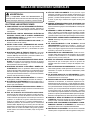
GENERAL SAFETY RULES
WARNING:
Read and understand all instructions. Failure to follow
all instructions listed below, may result in electric shock,
fire and/or serious personal injury.
READ ALL INSTRUCTIONS
KNOW YOUR POWER TOOL. Read the operator’s manual
carefully. Learn the applications and limitations as well
as the specific potential hazards related to this tool.
GUARD AGAINST ELECTRICAL SHOCK BY PREVENT-
ING BODY CONTACT WITH GROUNDED SURFACES.
For example: pipes, radiators, ranges, refrigerator enclo-
sures.
KEEP GUARDS IN PLACE and in good working order.
REMOVE ADJUSTING KEYS AND WRENCHES. Form
habit of checking to see that keys and adjusting wrenches
are removed from tool before turning it on.
KEEP WORK AREA CLEAN. Cluttered areas and benches
invite accidents. DO NOT leave tools or pieces of wood
on the tool while it is in operation.
DO NOT USE IN DANGEROUS ENVIRONMENTS. Do
not use power tools in damp or wet locations or expose
to rain. Keep the work area well lit.
KEEP CHILDREN AND VISITORS AWAY. All
visitors should wear safety glasses and be kept a safe
distance from work area. Do not let visitors contact
tool or extension cord while operating.
MAKE WORKSHOP CHILDPROOF with padlocks,
master switches, or by removing starter keys.
DON’T FORCE THE TOOL. It will do the job better and
safer at the feed rate for which it was designed.
USE THE RIGHT TOOL. Do not force the tool or attach-
ment to do a job for which it was not designed.
USE THE PROPER EXTENSION CORD. Make sure your
extension cord is in good condition. Use only a cord heavy
enough to carry the current your product will draw. An
undersized cord will cause a drop in line voltage result-
ing in loss of power and overheating. A wire gauge size
(A.W.G.) of at least 14 is recommended for an extension
cord 50 feet or less in length. If in doubt, use the next
heavier gauge. The smaller the gauge number, the heavier
the cord.
DRESS PROPERLY. Do not wear loose clothing,
neckties, or jewelry that can get caught and draw you into
moving parts. Rubber gloves and nonskid footwear are
recommended when working outdoors. Also wear
protective hair covering to contain long hair.
ALWAYS WEAR SAFETY GLASSES WITH SIDE
SHIELDS. Everyday eyeglasses have only impact-
resistant lenses, they are NOT safety glasses.
SECURE WORK. Use clamps or a vise to hold work
when practical, it is safer than using your hand and frees
both hands to operate the tool.
DO NOT OVERREACH. Keep proper footing and
balance at all times.
MAINTAIN TOOLS WITH CARE. Keep tools sharp
and clean for better and safer performance. Follow
instructions for lubricating and changing accessories.
DISCONNECT TOOLS. When not in use, before
servicing, or when changing attachments, blades, bits,
cutters, etc., all tools should be disconnected from power
source.
AVOID ACCIDENTAL STARTING. Be sure switch is off
when plugging in any tool.
USE RECOMMENDED ACCESSORIES. Consult the
operator’s manual for recommended accessories. The
use of improper accessories may result in injury.
NEVER STAND ON TOOL. Serious injury could occur if
the tool is tipped or if the cutting tool is unintentionally
contacted.
CHECK DAMAGED PARTS. Before further use of the
tool, a guard or other part that is damaged should be
carefully checked to determine that it will operate properly
and perform its intended function. Check for alignment
of moving parts, binding of moving parts, breakage of
parts, mounting and any other conditions that may affect
its operation. A guard or other part that is damaged must
be properly repaired or replaced by an authorized service
center to avoid risk of personal injury.
USE THE RIGHT DIRECTION OF FEED. Feed work into
a blade or cutter against the direction of rotation of the
blade or cutter only.
NEVER LEAVE TOOL RUNNING UNATTENDED. TURN
THE POWER OFF. Don’t leave tool until it comes to a
complete stop.
PROTECT YOUR LUNGS. Wear a face or dust mask if
the cutting operation is dusty.
PROTECT YOUR HEARING. Wear hearing protection
during extended periods of operation.
DO NOT ABUSE CORD. Never carry tool by the cord or
yank it to disconnect from receptacle. Keep cord from
heat, oil, and sharp edges.
USE OUTDOOR EXTENSION CORDS. When tool
is used outdoors, use only extension cords with
approved ground connection that are intended for use
outdoors and so marked.
KEEP BLADES CLEAN, SHARP, AND WITH
SUFFICIENT SET. Sharp blades minimize stalling
and kickback.
BLADE COASTS AFTER BEING TURNED OFF.

3
GENERAL SAFETY RULES
NEVER USE IN AN EXPLOSIVE ATMOSPHERE.
Normal sparking of the motor could ignite fumes.
INSPECT TOOL CORDS PERIODICALLY. If
damaged, have repaired by a qualified service technician at
an authorized service facility. Repair or replace a damaged
or worn cord immediately. Stay constantly aware of cord
location and keep it well away from the rotating blade.
INSPECT EXTENSION CORDS PERIODICALLY and
replace if damaged.
POLARIZED PLUGS. To reduce the risk of electric shock,
this tool has a polarized plug (one blade is wider than
the other). This plug will fit in a polarized outlet only one
way. If the plug does not fit fully in the outlet, reverse the
plug. If it still does not fit, contact a qualified electrician
to install the proper outlet. Do not change the plug in any
way.
KEEP TOOL DRY, CLEAN, AND FREE FROM OIL AND
GREASE. Always use a clean cloth when cleaning. Never
use brake fluids, gasoline, petroleum-based products, or
any solvents to clean tool.
STAY ALERT AND EXERCISE CONTROL. Watch what
you are doing and use common sense. Do not operate
tool when you are tired. Do not rush.
DO NOT USE TOOL IF SWITCH DOES NOT TURN IT
ON AND OFF. Have defective switches replaced by an
authorized service center.
SPECIFIC SAFETY RULES
FIRMLY CLAMP OR BOLT your tool to a workbench or
table at approximately hip height.
KEEP HANDS AWAY FROM CUTTING AREA. Do not
reach underneath work or in blade cutting path with your
hands and fingers for any reason. Always turn the power
off.
ALWAYS SUPPORT LONG WORKPIECES while cutting
to minimize risk of blade pinching and kickback. Saw may
slip, walk or slide while cutting long or heavy boards.
ALWAYS USE A CLAMP to secure the workpiece when
possible.
BE SURE THE BLADE CLEARS THE WORKPIECE.
Never start the saw with the blade touching the
workpiece. Allow motor to come up to full speed
before starting cut.
NEVER cut more than one piece at a time. DO NOT
STACK more than one workpiece on the saw table at a
time.
MAKE SURE THE MITER TABLE AND SAW ARM
(BEVEL FUNCTION) ARE LOCKED IN POSITION
BEFORE OPERATING YOUR SAW. Lock the miter
table by securely tightening the miter lock handle. Lock
the saw arm (bevel function) by securely tightening the
bevel lock knob.
NEVER USE A LENGTH STOP ON THE FREE SCRAP
END OF A CLAMPED WORKPIECE. NEVER hold onto
or bind the free scrap end of the workpiece in any opera-
tion. If a work clamp and length stop are used together,
they must both be installed on the same side of the saw
table to prevent the saw from catching the loose end and
kicking up.
NEVER PERFORM ANY OPERATION FREEHAND.
Always place the workpiece to be cut on the miter table
and position it firmly against the fence as a backstop.
Always use the fence.
NEVER hand hold a workpiece that is too small to be
clamped. Keep hands clear of the cutting area.
USE ONLY CORRECT BLADES. Do not use blades with
incorrect size holes. Never use blade washers or blade
bolts that are defective or incorrect. The maximum blade
capacity of your saw is 7-1/4 in.
BEFORE MAKING A CUT, BE SURE ALL ADJUST-
MENTS ARE SECURE.
BE SURE BLADE PATH IS FREE OF NAILS. Inspect for
and remove all nails from lumber before cutting.
NEVER TOUCH BLADE or other moving parts during
use.
NEVER START A TOOL WHEN ANY ROTATING COM-
PONENT IS IN CONTACT WITH THE WORKPIECE.
DO NOT OPERATE A TOOL WHILE UNDER THE
INFLUENCE OF DRUGS, ALCOHOL, OR ANY
MEDICATION.
WHEN SERVICING use only identical replacement parts.
Use of any other parts may create a hazard or cause
product damage.
USE ONLY RECOMMENDED ACCESSORIES listed
in this manual or addendums. Use of accessories that
are not listed may cause the risk of personal injury.
Instructions for safe use of accessories are included
with the accessory.
DOUBLE CHECK ALL SETUPS. Make sure blade is
tight and not making contact with saw or workpiece
before connecting to power supply.

4
SPECIFIC SAFETY RULES
NEVER reach behind, under, or within three inches of the
blade and its cutting path with hands and fingers for any
reason.
NEVER reach to pick up a workpiece, a piece of scrap,
or anything else that is in or near the cutting path of the
blade.
NEVER move the workpiece or make adjustment to any
cutting angle while the saw is running and the blade is
rotating. Any slip can result in contact with the blade
causing serious personal injury.
AVOID AWKWARD OPERATIONS AND HAND
POSITIONS where a sudden slip could cause your
hand to move into the blade. ALWAYS make sure you
have good balance. NEVER operate the miter saw
on the floor or in a crouched position.
NEVER stand or have any part of the body in line with
the path of the saw blade.
ALWAYS release the power switch and allow the saw blade
to stop rotating before raising it out of the workpiece.
DO NOT TURN THE MOTOR SWITCH ON AND OFF
RAPIDLY. This could cause the saw blade to loosen
and could create a hazard. Should this ever occur,
stand clear and allow the saw blade to come to a
complete stop. Disconnect your saw from the power
supply and securely retighten the blade bolt.
IF ANY PART OF THIS MITER SAW IS MISSING or
should break, bend, or fail in any way, or should any
electrical component fail to perform properly, shut off
the power switch, remove the miter saw plug from the
power source and have damaged, missing, or failed parts
replaced before resuming operation.
ALWAYS STAY ALERT! Do not allow familiarity (gained
from frequent use of the saw) to cause a careless
mistake. ALWAYS REMEMBER that a careless frac-
tion of a second is sufficient to inflict severe injury.
IF THE POWER SUPPLY CORD IS DAMAGED, it must
be replaced only by the manufacturer or by an authorized
service center to avoid risk.
MAKE SURE THE WORK AREA HAS AMPLE LIGHTING
to see the work and that no obstructions will interfere with
safe operation BEFORE performing any work using the
saw.
ALWAYS TURN OFF THE SAW before disconnecting it
to avoid accidental starting when reconnecting to power
supply. NEVER leave the saw unattended while connected
to a power source.
TURN OFF TOOL and wait for saw blade to come to
a complete stop before moving workpiece or changing
settings.
THIS TOOL should have the following markings:
a) Wear eye protection.
b) Keep hands out of path of saw blade.
c) Do not operate saw without guards in place.
d) Do not perform any operation freehand.
e) Never reach around saw blade.
f) Turn off tool and wait for saw blade to stop before
moving workpiece or changing settings.
g) Disconnect power (or unplug tool as applicable)
before changing blade or servicing.
h) No load speed.
ALWAYS carry the tool only by the “D” handle.
AVOID direct eye exposure when using the laser guide.
THIS SAW CAN TIP OVER if the saw head is released
suddenly and the saw is not secured to a work sur-
face. ALWAYS secure this saw to a stable work sur-
face before any use to avoid serious personal injury.
SAVE THESE INSTRUCTIONS. Refer to them
frequently and use to instruct other users. If you loan
someone this tool, loan them these instructions also.

5
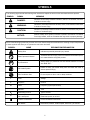
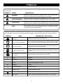
The following signal words and meanings are intended to explain the levels of risk associated with this product.
SYMBOL SIGNAL MEANING
DANGER:
Indicates an imminently hazardous situation, which, if not avoided, will result
in death or serious injury.
WARNING:
Indicates a potentially hazardous situation, which, if not avoided, could result
in death or serious injury.
CAUTION:
Indicates a potentially hazardous situation, which, if not avoided, may result
in minor or moderate injury.
NOTICE:
(Without Safety Alert Symbol) Indicates important information not related
to an injury hazard, such as a situation that may result in property damage.
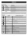
SYMBOLS
Some of the following symbols may be used on this tool. Please study them and learn their meaning. Proper interpretation
of these symbols will allow you to operate the tool better and safer.
SYMBOL NAME DESIGNATION/EXPLANATION
Safety Alert Indicates a potential personal injury hazard.
Read Operator’s Manual
To reduce the risk of injury, user must read and understand opera-
tor’s manual before using this product.
Eye Protection
Always wear eye protection with side shields marked to comply
with ANSI Z87.1.
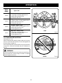
No Hands Symbol
Failure to keep your hands away from the blade will result in
serious personal injury.
Wet Conditions Alert Do not expose to rain or use in damp locations.
V
Volts Voltage
A
Amperes Current
Hz
Hertz Frequency (cycles per second)
min
Minutes Time
Alternating Current Type of current
n
o
No Load Speed Rotational speed, at no load
Class II Construction Double-insulated construction
.../min
Per Minute Revolutions, strokes, surface speed, orbits etc., per minute

6
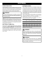
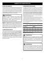
ELECTRICAL
DOUBLE INSULATION
Double insulation is a concept in safety in electric power tools,
which eliminates the need for the usual three-wire grounded
power cord. All exposed metal parts are isolated from the
internal metal motor components with protecting insulation.
Double insulated tools do not need to be grounded.
WARNING:
The double insulated system is intended to protect the
user from shock resulting from a break in the tool’s in-
ternal wiring. Observe all normal safety precautions to
avoid electrical shock.
NOTE: Servicing of a product with double insulation requires
extreme care and knowledge of the system and should be
performed only by a qualified service technician. For service,
we suggest you return the tool to your nearest authorized
service center for repair. Always use original factory replace-
ment parts when servicing.
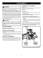
ELECTRICAL CONNECTION
This tool has a precision-built electric motor. It should be
connected to a power supply that is 120 volts, AC only
(normal household current), 60 Hz. Do not operate this tool
on direct current (DC). A substantial voltage drop will cause
a loss of power and the motor will overheat. If the tool does
not operate when plugged into an outlet, double-check the
power supply.
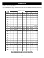
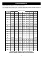
EXTENSION CORDS
When using a power tool at a considerable distance from
a power source, be sure to use an extension cord that has
the capacity to handle the current the product will draw. An
undersized cord will cause a drop in line voltage, resulting in
overheating and loss of power. Use the chart to determine
the minimum wire size required in an extension cord. Only
round jacketed cords listed by Underwriter’s Laboratories
(UL) should be used.
When working outdoors with a product, use an extension
cord that is designed for outside use. This type of cord is
designated with “WA” or “W” on the cord’s jacket.
Before using any extension cord, inspect it for loose or
exposed wires and cut or worn insulation.
**Ampere rating (on product data plate)
0-2.0 2.1-3.4 3.5-5.0 5.1-7.0 7.1-12.0 12.1-16.0
Cord Length Wire Size (A.W.G.)
25' 16 16 16 16 14 14
50' 16 16 16 14 14 12
100' 16 16 14 12 10 —
**Used on 12 gauge - 20 amp circuit
NOTE: AWG = American Wire Gauge
WARNING:
Keep the extension cord clear of the working area.
Position the cord so that it will not get caught on lumber,
tools, or other obstructions while you are working with
a power tool. Failure to do so can result in serious per-
sonal injury.
WARNING:
Check extension cords before each use. If damaged
replace immediately. Never use tool with a damaged cord
since touching the damaged area could cause electrical
shock resulting in serious injury.

7
GLOSSARY OF TERMS
Push Blocks (for jointer planers)
Device used to feed the workpiece over the jointer planer
cutterhead during any operation. This aid helps keep the
operator’s hands well away from the cutterhead.
Push Blocks (for table saws)
Device used to hold the workpiece during cutting opera-
tions. This aid helps keep the operator’s hands well away
from the blade.
Push Sticks (for table saws)
Device used to push the workpiece during cutting operations.
A push stick should be used for narrow ripping operations.
The aid helps keep the operator’s hands well away from
the blade.
Resaw
A cutting operation to reduce the thickness of the workpiece
to make thinner pieces.
Resin
A sticky, sap-based substance that has hardened.
Revolutions Per Minute (RPM)
The number of turns completed by a spinning object in one
minute.
Ripping or Rip Cut
A cutting operation along the length of the workpiece.
Riving Knife/Spreader/Splitter (table saws)
A metal piece, slightly thinner than the blade, which helps
keep the kerf open and also helps to prevent kickback.
Saw Blade Path
The area over, under, behind, or in front of the blade. As it
applies to the workpiece, that area which will be or has been
cut by the blade.
Set
The distance that the tip of the saw blade tooth is bent (or
set) outward from the face of the blade.
Snipe (planers)
Depression made at either end of a workpiece by cutter
blades when the workpiece is not properly supported.
Taper Cut
A cut where the material being cut has a different width at
the beginning of the cut from the the end.
Through Sawing
Any cutting operation where the blade extends completely
through the thickness of the workpiece.
Throw-Back
The throwing back of a workpiece usually caused by the
workpiece being dropped into the blade or being placed
inadvertently in contact with the blade.
Workpiece or Material
The item on which the operation is being done.
Worktable
Surface where the workpiece rests while performing a
cutting, drilling, planing, or sanding operation.
Anti-Kickback Pawls (radial arm and table saws)
A device which, when properly installed and maintained,
is designed to stop the workpiece from being kicked back
toward the front of the saw during a ripping operation.
Arbor
The shaft on which a blade or cutting tool is mounted.
Bevel Cut
A cutting operation made with the blade at any angle other
than 90° to the table surface.
Compound Cut
A cross cut made with both a miter and a bevel angle.
Cross Cut
A cutting or shaping operation made across the grain or the
width of the workpiece.
Cutterhead (planers and jointer planers)
A rotating cutterhead with adjustable blades or knives. The
blades or knives remove material from the workpiece.
Dado Cut
A non-through cut which produces a square-sided notch or
trough in the workpiece (requires a special blade).
Featherboard
A device used to help control the workpiece by holding
it securely against the table or fence during any ripping
operation.
FPM or SPM
Feet per minute (or strokes per minute), used in reference
to blade movement.
Freehand
Performing a cut without the workpiece being guided by a
fence, miter gauge, or other aids.
Gum
A sticky, sap-based residue from wood products.
Heel
Alignment of the blade to the fence.
Kerf
The material removed by the blade in a through cut or the
slot produced by the blade in a non-through or partial cut.
Kickback
A hazard that can occur when the blade binds or stalls,
throwing the workpiece back toward operator.
Miter Cut
A cutting operation made with the workpiece at any angle
to the blade other than 90°.
Non-Through Cuts
Any cutting operation where the blade does not extend
completely through the thickness of the workpiece.
Pilot Hole (drill presses)
A small hole drilled in a workpiece that serves as a guide for
drilling large holes accurately.

8
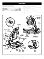
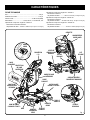
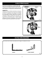
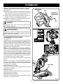
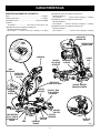
FEATURES
Fig. 1
PRODUCT SPECIFICATIONS
Arbor ......................................................................... 5/8 in.
Blade Diameter ...................................................... 7-1/4 in.
No Load Speed ....................................5,800 r/min. (RPM)
Input .................................. 120 V, AC only, 60 Hz, 9 Amps
Cutting Capacity with Miter at 0°/Bevel 0°:
Maximum lumber sizes ..................... 1-1/2 in. x 4-1/4 in.
Cutting Capacity with Miter at 45°/Bevel 0°:
Maximum lumber sizes ............................1-1/2 in. x 3 in.
Cutting Capacity with Miter at 0°/Bevel 45°:
Maximum lumber sizes ..................... 1-1/2 in. x 3-1/2 in.
Cutting Capacity with Miter at 45°/Bevel 45°:
Maximum lumber sizes ............................... 3/4 in. x 3 in.
LOWER
BLADE
GUARD
UPPER
BLADE
GUARD
“D” HANDLE
BASE
MITER
LOCK LEVER
BEVEL
LOCK
KNOB
SWITCH TRIGGER
“NO HANDS ZONE”
LABEL
“NO HANDS ZONE”
BOUNDARY LINE
BLADE
WRENCH
MITER
TABLE
DUST BAG
WORK
CLAMP
MITER
SCALE
MITER
FENCE
LASER
GUIDE
LASER GUIDE
SWITCH
THROAT
PLATE
REAR BRACKET/
CARRYING HANDLE
BEVEL
SCALE
LOCK PIN

9
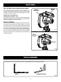
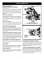
FEATURES
Fig. 3
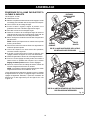
KNOW YOUR COMPOUND MITER SAW
See Figures 1 - 5.
The safe use of this product requires an understanding of
the information on the tool and in this operator’s manual as
well as a knowledge of the project you are attempting. Before
use of this product, familiarize yourself with all operating
features and safety rules.
9 AMP MOTOR
The saw has a powerful 9 amp motor with sufficient power to
handle tough cutting jobs. It is made with all ball bearings, and
has externally accessible brushes for ease of servicing.
7-1/4 in. BLADE
A 7-1/4 in. blade is included with the compound miter saw.
It will cut materials up to 1-1/2 in. thick or 4-1/4 in. wide,
depending upon the angle at which the cut is being made.
BEVEL LOCK KNOB
The bevel lock knob securely locks your compound miter
saw at desired bevel angles. Positive stop adjustment
screws have been provided on each side of the saw arm.
These adjustment screws are for making fine adjustments
at 0° and 45°.
BLADE WRENCH STORAGE
A blade wrench is packed with the saw. One end of the
wrench is a phillips screwdriver and the other end is a hex
key. Use the hex key end when installing or removing blade
and the phillips end when removing or loosening screws. A
storage area for the blade wrench is located in the saw’s base.
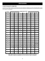
DETENTS ON MITER TABLE
Detents have been provided at 0°, 15°, 22-1/2°, 31.62°, and
45°. The 15°, 22-1/2°, 31.62°, and 45° detents have been
provided on both the left and right side of the miter table.
LASER GUIDE
For more accurate cuts, a laser guide is included with your
miter saw. When used properly, the laser guide makes ac-
curate, precision cutting simple and easy.
MITER FENCE
The miter fence on the compound miter saw has been
provided to hold your workpiece securely against when
making all cuts.
MITER LOCK LEVER
The miter lock lever securely locks the saw at desired miter
angles. To adjust miter table, pull miter lock lever forward and
up to unlock table. Push lever back and down to lock table.
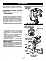
Fig. 2
SAW ARM LOCKED IN DOWN POSITION
UNLOCK
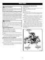
REAR BRACKET/CARRYING HANDLE
For convenience when carrying or transporting the miter
saw from one place to another, a carrying handle has been
provided at the rear of the saw. To transport, turn off and
unplug the saw, then lower the saw arm and lock it in the
down position. Lock saw arm by depressing the lock pin.
LOCK PIN
TO
UNLOCK
MITER
LOCK LEVER
TO
LOCK

10
FEATURES
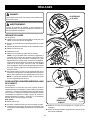
SELF-RETRACTING LOWER BLADE GUARD
The lower blade guard is made of shock-resistant, see-
through plastic that provides protection from each side of
the blade. It retracts over the upper blade guard as the saw
is lowered into the workpiece.
SPINDLE LOCK BUTTON
The spindle lock button locks the spindle stopping the
blade from rotating. Depress and hold the lock button while
installing, changing, or removing blade.
SWITCH TRIGGER
The saw will not start until you depress the switch lock with
your thumb then squeeze the switch trigger. To prevent
unauthorized use of the compound miter saw, disconnect it
from the power supply and lock the switch in the off position.
To lock the switch, install a padlock (not included) through
the hole in the switch trigger. A lock with a long shackle of
5/16 in. diameter may be used. When the lock is installed
and locked, the switch is inoperable. Store the padlock key
in another location.
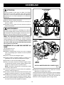
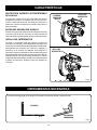
The following tool (not included) is needed for making adjustments or installing the blade:
TOOLS NEEDED
Fig. 6
Fig. 5
PADLOCK
SWITCH
TRIGGER
COMBINATION SQUARE
SQUARE
SPINDLE
LOCK BUTTON
SWITCH
TRIGGER
Fig. 4

11
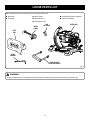
LOOSE PARTS LIST
Fig. 7
WARNING:
The use of attachments or accessories not listed might be hazardous and could cause serious personal injury.
The following items are included with your compound miter saw:
WORK
CLAMP
DUST
BAG
BLADE
WRENCH
AAA
BATTERIES
REAR BRACKET/
CARRYING HANDLE
MITER SAW
Miter Saw
Dust Bag
Work Clamp
Blade Wrench
AAA Batteries (2)
Rear Bracket/Carrying Handle
Operator’s Manual

12
UNPACKING
This product requires assembly.
Carefully lift miter saw from the carton by the “D” handle
and the saw base, and place it on a level work surface.
WARNING:
Do not use this product if any parts on the Loose Parts List
are already assembled to your product when you unpack
it. Parts on this list are not assembled to the product by
the manufacturer and require customer installation. Use
of a product that may have been improperly assembled
could result in serious personal injury.
The saw has been shipped with the saw arm secured in
the down position. To release the saw arm, push down
on the top of the saw arm, cut the tie-wrap, and pull out
on the lock pin.
Lift the saw arm by the handle. Hand pressure should
remain on the saw arm to prevent sudden rise upon
release of the tie wrap.
Inspect the tool carefully to make sure no breakage or
damage occurred during shipping.
Do not discard the packing material until you have care-
fully inspected and satisfactorily operated the tool.
The saw is factory set for accurate cutting. After
assembling it, check for accuracy. If shipping has
influenced the settings, refer to specific procedures
explained later in this manual.
If any parts are damaged or missing, please call
1-800-525-2579 for assistance.
WARNING:
If any parts are damaged or missing do not operate this
product until the parts are replaced. Use of this product
with damaged or missing parts could result in serious
personal injury.
WARNING:
Do not attempt to modify this tool or create accessories
not recommended for use with this tool. Any such altera-
tion or modification is misuse and could result in a hazard-
ous condition leading to possible serious personal injury.
WARNING:
Do not connect to power supply until assembly is
complete. Failure to comply could result in accidental
starting and possible serious personal injury.
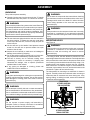
ASSEMBLY
WARNING:
Do not start the compound miter saw without checking
for interference between the blade and the miter fence.
Damage could result to the blade if it strikes the miter
fence during operation of the saw and may result in
personal injury.
WARNING:
Always make sure the compound miter saw is securely
mounted to a workbench or an approved workstand.
Failure to heed this warning can result in serious personal
injury.
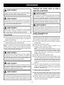
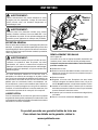
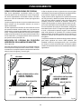
MOUNTING HOLES
See Figure 8.
WARNING:
Always make sure the compound miter saw is securely
mounted to a workbench or an approved workstand.
Failure to heed this warning can result in serious
personal injury.
If not using a stand, the saw should be mounted to a firm
supporting surface such as a workbench. Four bolt holes have
been provided in the saw base for this purpose. Each of the
four mounting holes should be bolted securely using 1/4 in.
machine bolts, lock washers, and hex nuts (not included).
Bolts should be of sufficient length to accommodate the
saw base, lock washers, hex nuts, and the thickness of the
workbench. Tighten all four bolts securely.
The hole pattern for mounting to a workbench is shown in
figure 8. Carefully check the workbench after mounting to
make sure that no movement can occur during use. If any
tipping, sliding, or walking is noted, secure the workbench
to the floor before operating.
TRACE HOLES
AT THESE LOCATIONS
FOR HOLE PATTERN
TRACE HOLES
AT THESE LOCATIONS
FOR HOLE PATTERN
Fig. 8
MOUNTING
SURFACE
BASE

13
31.6
22.5
22.5
31.6
ASSEMBLY
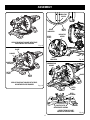
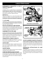
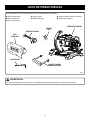
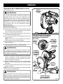
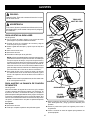
INSTALLING THE REAR BRACKET/CARRYING
HANDLE
See Figure 9.
CAUTION:
A rear bracket is included with this miter saw to prevent
tipping if the saw arm is released suddenly. Do not use
this saw before installing the rear bracket/carrying handle
and securely mounting the saw to a work surface or stand
and may result in personal injury.
Remove the screws from the rear bracket/carrying handle
and set aside.
Slide the bracket in the openings on the saw base, align-
ing the holes underneath the base with the holes in the
bracket.
Insert the screws into the holes and tighten securely.
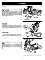
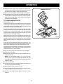
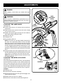
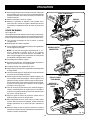
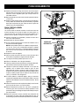
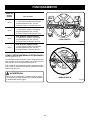
DUST BAG
See Figure 10.
A dust bag is provided for use on the miter saw. It fits over
the exhaust port on the upper blade guard. Squeeze the two
metal clips to open the mouth of the bag and slide it on the
exhaust port. Release the clips. The metal ring in the bag
should lock in between the grooves on the exhaust port.
To remove the dust bag for emptying, simply reverse the
above procedure.
WORK CLAMP
See Figure 11.
The work clamp provides greater control by clamping the
workpiece to the fence. It also prevents the workpiece from
creeping toward the saw blade. This is very helpful when
cutting compound miters.
Depending on the cutting operation and the size of the
workpiece, it may be necessary to use a C-clamp instead
of the work clamp to secure the workpiece to the miter table
prior to making the cut.
WARNING:
In some operations, the work clamp assembly may
interfere with the operation of the blade guard assembly.
Always make sure there is no interference with the blade
guard prior to beginning any cutting operation to reduce
the risk of serious personal injury.
To install the work clamp:
Place the shaft of the work clamp in either hole on the
miter table base.
Rotate the knob on the work clamp clockwise to move it
in or counterclockwise to move it out as needed.
Fig. 11
Fig. 10
DUST
BAG
EXHAUST
PORT
REAR BRACKET/
CARRYING HANDLE
SCREWS
Fig. 9
BASE
WORK
CLAMP

14
ASSEMBLY
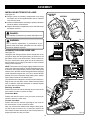
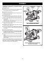
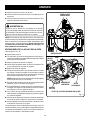
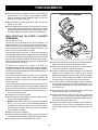
INSTALLING BATTERIES FOR LASER
See Figure 12.
Remove screw from battery compartment cover using
the Phillips end of the supplied blade wrench. Remove
cover and set aside.
Install two AAA batteries according to polarity indicators
inside the battery compartment.
Replace the battery compartment cover. Reinstall screw
and tighten securely.
DANGER:
Laser radiation. Avoid direct eye contact with light source.
WARNING:
Use of controls, adjustments, or performance of pro-
cedures other than those specified here can result in
hazardous radiation exposure.
ALIGNING THE LASER GUIDE LINE
See Figure 13.
Unplug the saw. Using a square, draw a straight line on the
workpiece. When the laser guide switch is turned on it will
generate a red line on the work surface. This line will let you
see your mark and the laser guide line at the same time,
and will assist you in lining up the mark for more accurate
cutting of the workpiece.
NOTE: The broken line may begin slightly skewed off of the
mark in the uppermost position. As the saw blade assembly
is lowered, at the approximate point the lower blade guard
starts to move, the laser line will be aligned with the mark and
remain aligned throughout the cut. This is normal. NEVER
attempt to move the workpiece while making a cut. Always
keep hands outside the “No Hands Zone”.
Once both lines are in alignment, do not move the workpiece.
Plug the saw into the power source. Make several practice
cuts on different styles and thickness of material. Repeat
the steps above as necessary.
Removing Your Mark:
Position the laser line near the left edge of your mark on the
work surface in order to remove the mark.
To Cut Your Mark:
Position the laser line near or over your mark on the work
surface in order to cut the mark.
To Leave Your Mark:
Position the laser line near the right edge of your mark on
the work surface in order to leave the mark.
After you have become familiar with using the laser guide,
you will be able to remove, cut, or leave your mark on the
work surface. Practice will teach you the correct position for
aligning the laser line with your mark.
Fig. 12
BATTERIES
COMPARTMENT
COVER
LASER GUIDE
SWITCH
SCREW
Fig. 13
LASER
LINE
Lock
trigger prior to adjusting
laser. AVOID EXPOSURE:
Laser radiation emitted
from this aperture.
Fixer gâchette avant
laser est réglagé.
EVITER L’EXPOSITION :
Rayonnement laser
émise de cet orifice.
Asegure gatillo antes de
ajuste de laser. EVITE LA
EXPOSIOCIÔN: Radiactiôn
laser se emite por esta
abertura.

15
ASSEMBLY
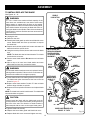
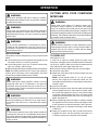
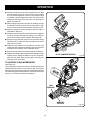
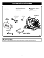
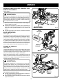
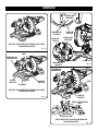
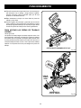
TO INSTALL/REPLACE THE BLADE
See Figures 14 - 15.
WARNING:
A 7-1/4 in. blade is the maximum blade capacity of the
saw. Never use a blade that is too thick to allow outer
blade washer to engage with the flats on the spindle.
Larger blades will come in contact with the blade guards,
while thicker blades will prevent the blade bolt from se-
curing the blade on the spindle. Either of these situations
could result in a serious accident and can cause serious
personal injury.
Unplug the saw.
Raise the saw arm.
Rotate lower blade guard up and remove blade bolt cover
screw. Rotate blade bolt cover up and back to expose
the blade bolt.
Depress and hold the spindle lock button and rotate the
blade bolt until the spindle locks.
Using the wrench provided, loosen and remove the blade
bolt.
NOTE: The blade bolt has left hand threads. Turn blade
bolt clockwise to loosen.
Remove outer blade washer. Do not remove inner blade
washer.
Wipe a drop of oil onto inner blade washer and outer
blade washer where they contact the blade.
WARNING:
If inner blade washer has been removed, replace it before
placing blade on spindle. Failure to do so could cause an
accident since blade will not tighten properly.
Fit saw blade inside lower blade guard and onto spindle.
The blade teeth point downward at the front of saw as
shown in figure 15.
Replace outer blade washer. Double “D” flats on blade
washers align with flats on spindle.
Depress and hold spindle lock button and replace blade
bolt.
NOTE: The blade bolt has left hand threads. Turn blade bolt
counterclockwise to tighten.
CAUTION:
Always install the blade with the blade teeth and the
arrow printed on the side of the blade pointing down at
the front of the saw. The direction of blade rotation is
also stamped with an arrow on the upper blade guard.
Tighten blade bolt securely.
Replace the lower blade guard and blade bolt cover.
Replace blade bolt cover screw and tighten securely.
31.6
22.5
22.5
31.6
SPINDLE
LOCK BUTTON
BLADE
BOLT
Fig. 15
LOWER
BLADE GUARD
BLADE
TO
TIGHTEN
TO
LOOSEN
FLAT(S)
ON SPINDLE
BLADE
BOLT
COVER
Fig. 14
NOTE: BEFORE USE,
REPLACE SCREW AND
TIGHTEN SECURELY
TO PREVENT GUARD
MOVEMENT
OUTER BLADE
WASHER WITH
DOUBLE “D”
FLATS
INNER BLADE WASHER WITH
DOUBLE “D” FLATS
BLADE BOLT COVER
SCREW

16
WARNING:
Make sure the spindle lock button is not engaged
before reconnecting saw into power source. Never engage
spindle lock button when blade is rotating.
NOTE: Many of the illustrations in this manual show only
portions of the compound miter saw. This is intentional so
that we can clearly show points being made in the illustra-
tions. Never operate the saw without all guards securely
in place and in good operating condition.
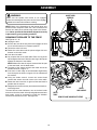
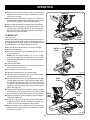
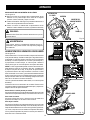
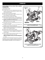
SQUARING THE BLADE TO THE FENCE
See Figures 16 - 19.
Unplug the saw.
Pull the saw arm all the way down and engage the lock
pin to hold the saw arm in transport position.
Unlock the miter lock lever.
Rotate the miter table until the pointer aligns with zero
dentent on the miter scale.
Lock the miter table.
Lay a square flat on the miter table. Place one leg of the
square against the fence. Slide the other leg of the square
against the flat part of saw blade.
NOTE: Make sure that the square contacts the flat part
of the saw blade, not the blade teeth.
The edge of the square and the saw blade should be
parallel as shown in figure 17.
If the front or back edge of the saw blade angles away
from the square as shown in figures 18-19, adjustments
are needed.
Using the blade wrench, loosen the socket head
screws that secure the miter fence to the miter table.
Rotate the miter fence left or right until the saw blade is
parallel with the square.
Retighten the screws securely and recheck the blade-to-
fence alignment.
The saw has two scale indicators, one on the bevel scale
and one on the miter scale. After squaring adjustments have
been made, it may be necessary to loosen the indicator
screws and reset them to zero. See figure 20.
ASSEMBLY
Fig. 16
FENCE
SOCKET HEAD
SCREW(S)
Fig. 17
VIEW OF BLADE SQUARE WITH FENCE
MITER
LOCK HANDLE
MITER
TABLE
BLADE
SQUARE
MITER
FENCE

17
ASSEMBLY
Fig. 19
MITER
TABLE
BLADE
SQUARE
Fig. 20
SCALE
INDICATOR
MITER
SCALE
INDICATOR
SCREW
Fig. 21
CORRECT VIEW OF BLADE
SQUARE WITH MITER TABLE
MITER
TABLE
COMBINATION
SQUARE
BLADE
BEVEL
LOCK KNOB
POSITIVE STOP
ADJUSTMENT SCREWS
INDICATOR
SCREW
BEVEL
SCALE
SCALE
INDICATOR
MITER
FENCE
SOCKET HEAD
SCREW(S)
Fig. 18
VIEW OF BLADE NOT SQUARE WITH FENCE,
ADJUSTMENTS ARE REQUIRED
VIEW OF BLADE NOT SQUARE WITH FENCE,
ADJUSTMENTS ARE REQUIRED

18
ASSEMBLY
SQUARING THE BLADE TO THE MITER TABLE
See Figures 19 - 23.
Unplug the saw.
Pull the saw arm all the way down and engage the lock
pin to hold the saw arm in transport position.
Unlock the miter lock lever.
Rotate the miter table until the pointer aligns with zero
detent on the miter scale.
Lock the miter lock.
Loosen bevel lock knob and set saw arm at 0
°
bevel (blade
set 90
°
to miter table). Tighten bevel lock knob at stop.
Place a square against the miter table and the flat part
of saw blade.
NOTE: Make sure that the square contacts the flat part
of the saw blade, not the blade teeth.
Rotate the blade by hand and check the blade-to-table
alignment at several points.
The edge of the square and the saw blade should be
parallel as shown in figure 21.
If the top or bottom of the saw blade angles away from
the square as shown in figures 22 and 23, adjustments
are needed.
Loosen the bevel lock knob.
Adjust positive stop adjustment screw to bring saw blade
into alignment with the square. See Positive Stop Adjust-
ment in the Adjustments section.
Retighten bevel lock knob. Recheck blade-to-table align-
ment.
NOTE: The above procedure can be used to check blade
squareness of the saw blade to the miter table at both 0
°
and 45
°
angles.
The saw has two scale indicators, one on the bevel scale
and one on the miter scale. After squaring adjustments have
been made, it may be necessary to loosen the indicator
screws and reset them to zero. See figure 20.
Fig. 22
Fig. 23
VIEW OF BLADE NOT SQUARE WITH MITER
TABLE, ADJUSTMENTS ARE REQUIRED
VIEW OF BLADE NOT SQUARE WITH MITER TABLE,
ADJUSTMENTS ARE REQUIRED
MITER
TABLE
COMBINATION
SQUARE
BLADE
BEVEL
LOCK KNOB

19
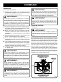
OPERATION
WARNING:
Do not allow familiarity with tools to make you careless.
Remember that a careless fraction of a second is sufficient
to inflict serious injury.
WARNING:
Always wear eye protection with side shields marked to
comply with ANSI Z87.1. Failure to do so could result in
objects being thrown into your eyes, resulting in possible
serious injury.
WARNING:
Do not use any attachments or accessories not recom-
mended by the manufacturer of this tool. The use of at-
tachments or accessories not recommended can result in
serious personal injury.
APPLICATIONS
This product has been designed only for the purposes listed
below:
Cross cutting wood, wood composition and plastic (do not
cut metals, ceramics, or masonry products.)
Cross cutting miters, joints, etc. for picture frames mold
-
ings, door casings, and fine joinery
Bevel cutting and compound cutting of lumber and moldings.
NOTE: The blade provided is fine for most wood cutting op
-
erations, but for fine joinery cuts or cutting plastic, use one of
the accessory blades available from the dealer.
WARNING:
Before starting any cutting operation, clamp or bolt the
compound miter saw to a workbench or an approved
workstand. Never operate the miter saw on the floor or in
a crouched position. Failure to heed this warning can result
in serious personal injury.
WARNING:
To avoid serious personal injury, always lock the miter lock
lever before making a cut. Failure to do so could result in
movement of the control arm or miter table while making
a cut.
WARNING:
To avoid serious personal injury, keep hands outside the
no hands zone, at least 3 in. from the blade. Never perform
any cutting operation freehand (without holding workpiece
against the fence). The blade could grab the workpiece if
it slips or twists.
CUTTING WITH YOUR COMPOUND
MITER SAW
WARNING:
When using a work clamp or C-clamp to secure your
workpiece, clamp workpiece on one side of the blade
only. The workpiece must remain free on one side of the
blade to prevent the blade from binding in workpiece. The
workpiece binding the blade will cause motor stalling and
kickback. This situation could cause an accident resulting
in possible serious personal injury.
WARNING:
NEVER move the workpiece or make adjustment to any
cutting angle while the saw is running and the blade is
rotating. Any slip can result in contact with the blade
causing serious personal injury.
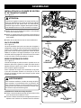
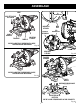
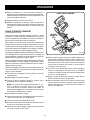
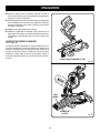
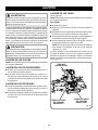
TO CROSS CUT
See Figures 24 - 25.
A cross cut is made by cutting across the grain of the
workpiece. A straight cross cut is made with the miter table
set at the 0° position. Miter cross cuts are made with the
miter table set at some angle other than zero.
Pull out the lock pin and lift saw arm to its full height.
Unlock the miter table.
Rotate the miter table until the pointer aligns with zero
on the miter scale.
NOTE: You can quickly locate 0°, 15°, 22-1/2°, 31.62°
and 45° left or right as you rotate the control arm. The
miter table will seat itself in one of the detent index points,
located in base.
Lock the miter table.
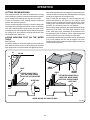
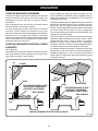
Place the workpiece flat on the miter table with one edge
securely against the fence. If the board is warped, place
the convex side against the fence. If the concave edge
of a board is placed against the fence, the board could
collapse on the blade at the end of the cut, jamming the
blade. See figure 31.
When cutting long pieces of lumber or molding, support
the opposite end of the stock with a roller stand or with
a work surface level with the saw table. See Figure 29.
Align cutting line on workpiece with edge of saw blade
or laser line.
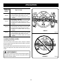
Grasp the workpiece firmly with one hand and secure
it against the fence. Use the optional work clamp or a
C-clamp to secure the workpiece when possible.

20
OPERATION
Before turning on the saw, perform a dry run of the cutting
operation just to make sure that no problems will occur
when the cut is made.
Grasp the saw handle firmly. Depress the switch lock
with thumb then squeeze the switch trigger. Allow several
seconds for the blade to reach maximum speed.
Slowly lower the blade into and through the workpiece.
Release the switch trigger and allow the blade to stop
rotating before raising the blade out of the workpiece.
Wait until the blade stops turning before removing the
workpiece from the miter table.
TO BEVEL CUT
See Figure 26.
A bevel cut is made by cutting across the grain of the workpiece
with the blade angled to the workpiece. A straight bevel cut
is made with the miter table set at the zero degree position
and the blade set at an angle between 0° and 45°.
Pull out the lock pin and lift saw arm to its full height.
Unlock the miter table.
Rotate the miter table until the pointer aligns with zero
on the miter scale.
NOTE: You can quickly locate 0°, 15°, 22-1/2°, 31.62°
and 45° left or right as you rotate the control arm. The
miter table will seat itself in one of the detent index points,
located in base.
Lock the miter table.
Loosen the bevel lock knob and move the saw arm to the
left to the desired bevel angle.
Bevel angles can be set from 0° to 45°.
Align the indicator point for the desired angle.
Once the saw arm has been set at the desired angle,
securely tighten the bevel lock knob.
Place the workpiece flat on the miter table with one edge
securely against the fence. If the board is warped, place
the convex side against the fence. If the concave edge
of a board is placed against the fence, the board could
collapse on the blade at the end of the cut, jamming the
blade. See figure 31.
When cutting long pieces of lumber or molding, support
the opposite end of the stock with a roller stand or with
a work surface level with the saw table. See Figure 29.
Align the cutting line on the workpiece with the edge of
saw blade or laser line.
Grasp the workpiece firmly with one hand and secure
it against the fence. Use the optional work clamp or a
C-clamp to secure the workpiece when possible.
Before turning on the saw, perform a dry run of the cutting
operation just to make sure that no problems will occur
when the cut is made.
BEVEL
SCALE
Fig. 26
Fig. 24
BEVEL CUT
MITER CUT
INDICATOR
POINT
Fig. 25
BEVEL
LOCK
KNOB
SWITCH
LOCK
WORK
CLAMP
CROSS CUT
LOCK PIN
Page is loading ...
Page is loading ...
Page is loading ...
Page is loading ...
Page is loading ...
Page is loading ...
Page is loading ...
Page is loading ...
Page is loading ...
Page is loading ...
Page is loading ...
Page is loading ...
Page is loading ...
Page is loading ...
Page is loading ...
Page is loading ...
Page is loading ...
Page is loading ...
Page is loading ...
Page is loading ...
Page is loading ...
Page is loading ...
Page is loading ...
Page is loading ...
Page is loading ...
Page is loading ...
Page is loading ...
Page is loading ...
Page is loading ...
Page is loading ...
Page is loading ...
Page is loading ...
Page is loading ...
Page is loading ...
Page is loading ...
Page is loading ...
Page is loading ...
Page is loading ...
Page is loading ...
Page is loading ...
Page is loading ...
Page is loading ...
Page is loading ...
Page is loading ...
Page is loading ...
Page is loading ...
Page is loading ...
Page is loading ...
Page is loading ...
Page is loading ...
Page is loading ...
Page is loading ...
Page is loading ...
Page is loading ...
Page is loading ...
Page is loading ...
Page is loading ...
Page is loading ...
Page is loading ...
Page is loading ...
Page is loading ...
Page is loading ...
Page is loading ...
Page is loading ...
-
 1
1
-
 2
2
-
 3
3
-
 4
4
-
 5
5
-
 6
6
-
 7
7
-
 8
8
-
 9
9
-
 10
10
-
 11
11
-
 12
12
-
 13
13
-
 14
14
-
 15
15
-
 16
16
-
 17
17
-
 18
18
-
 19
19
-
 20
20
-
 21
21
-
 22
22
-
 23
23
-
 24
24
-
 25
25
-
 26
26
-
 27
27
-
 28
28
-
 29
29
-
 30
30
-
 31
31
-
 32
32
-
 33
33
-
 34
34
-
 35
35
-
 36
36
-
 37
37
-
 38
38
-
 39
39
-
 40
40
-
 41
41
-
 42
42
-
 43
43
-
 44
44
-
 45
45
-
 46
46
-
 47
47
-
 48
48
-
 49
49
-
 50
50
-
 51
51
-
 52
52
-
 53
53
-
 54
54
-
 55
55
-
 56
56
-
 57
57
-
 58
58
-
 59
59
-
 60
60
-
 61
61
-
 62
62
-
 63
63
-
 64
64
-
 65
65
-
 66
66
-
 67
67
-
 68
68
-
 69
69
-
 70
70
-
 71
71
-
 72
72
-
 73
73
-
 74
74
-
 75
75
-
 76
76
-
 77
77
-
 78
78
-
 79
79
-
 80
80
-
 81
81
-
 82
82
-
 83
83
-
 84
84


Ask a question and I''ll find the answer in the document
Finding information in a document is now easier with AI
in other languages
- français: Ryobi TS1143L Mode d'emploi
- español: Ryobi TS1143L Guía del usuario