2 / 2
CRM-2HE
U
15-18 t1 t1 t1t2 t2
U
15-18
S
t1t2 t1t2 t2
B1 B3 B2
27
28 17
M 22x1
15
Warning
Technical parameters
Device is constructed for connection in 1-phase installation of AC/DC 12-240 V main
and must be installed according to norms valid in the state of application. Connection
according to the details in this direction. Installation, connection, setting and servicing
should be installed by quali ed electrician sta only, who has learnt these instruction
and functions of the device. This device contains protection against overvoltage peaks
and disturbancies in supply. For correct function of the protection of this device there
must be suitable protections of higher degree (A, B, C) installed in front of them.
According to standards elimination of disturbancies must be ensured. Before installation
the main switch must be in position “OFF” and the device should be de-energized.
Don´t install the device to sources of excessive electro-magnetic interference. By correct
installation ensure ideal air circulation so in case of permanent operation and higher
ambient temperature the maximal operating temperature of the device is not exceeded.
For installation and setting use screw-driver cca 2 mm. The device is fully-electronic -
installation should be carried out according to this fact. Non-problematic function
depends also on the way of transportation, storing and handling. In case of any signs of
destruction, deformation, non-function or missing part, don´t install and claim at your
seller.
Function
Number of functions:
Supply terminals:
Voltage range:
Power input (max.):
Max. dissipated power
(Un + terminals):
Supply voltage tolerance:
Supply indication:
Time ranges:
Time settings:
Time deviation:
Repeat accuracy:
Temperature coe cient:
Output
Number of contacts:
Rated current:
Breaking capacity:
Inrush current:
Switching voltage:
Output indication:
Mechanical life:
Electrical life (AC1):
Controlling
Control. voltage:
Power the control input:
Load between S-A2:
Glow tubes connetions:
Control. terminals:
Reset time:
Other information
Operating temperature:
Storage temperature:
Electrical strength:
Operating position:
Mounting:
Protection degree:
Overvoltage cathegory:
Pollution degree:
Max. cable size (mm2):
Dimensions:
Weight:
Standards:
2
A1 - A2
AC/DC 12 - 240 V (AC 50 - 60 Hz)
AC 0.7 - 3 VA / DC 0.5 - 1.7 W
4 W
-15%; + 10%
green LED
0.1 s - 100 days
rotary switch and external potentiometers
5 % - mechanical setting
0.2 % - set value stability
0.01 % / °C, at = 20 °C
1x changeover / SPDT (AgNi / Silver Alloy)
16 A / AC 1
4000 VA / AC1, 384 W / DC
30 A / < 3 s
250 V AC / 24 V DC
multifunction red LED
3x10⁷
0.7x10⁵
AC/DC 12 - 240 V (AC 50 - 60 Hz)
AC 0.025 - 0.2 VA / DC 0.1 - 0.7 W
Yes
No
A1-S
max. 150 ms
-20 °C to 55 °C (-4 °F to 131 °F)
-30 °C to 70 °C (-22 °F to 158 °F)
4 kV (supply - output)
any
DIN rail EN 60715
IP40 from front panel / IP20 terminals
III.
2
solid wire max. 1x 2.5 or 2x 1.5 /
with sleeve max. 1x 2.5 (AWG 12)
90 x 17.6 x 64 mm (3.5˝ x 0.7˝ x 2.5˝)
78 g (2.8 oz.)
EN 61812-1, EN 61010-1
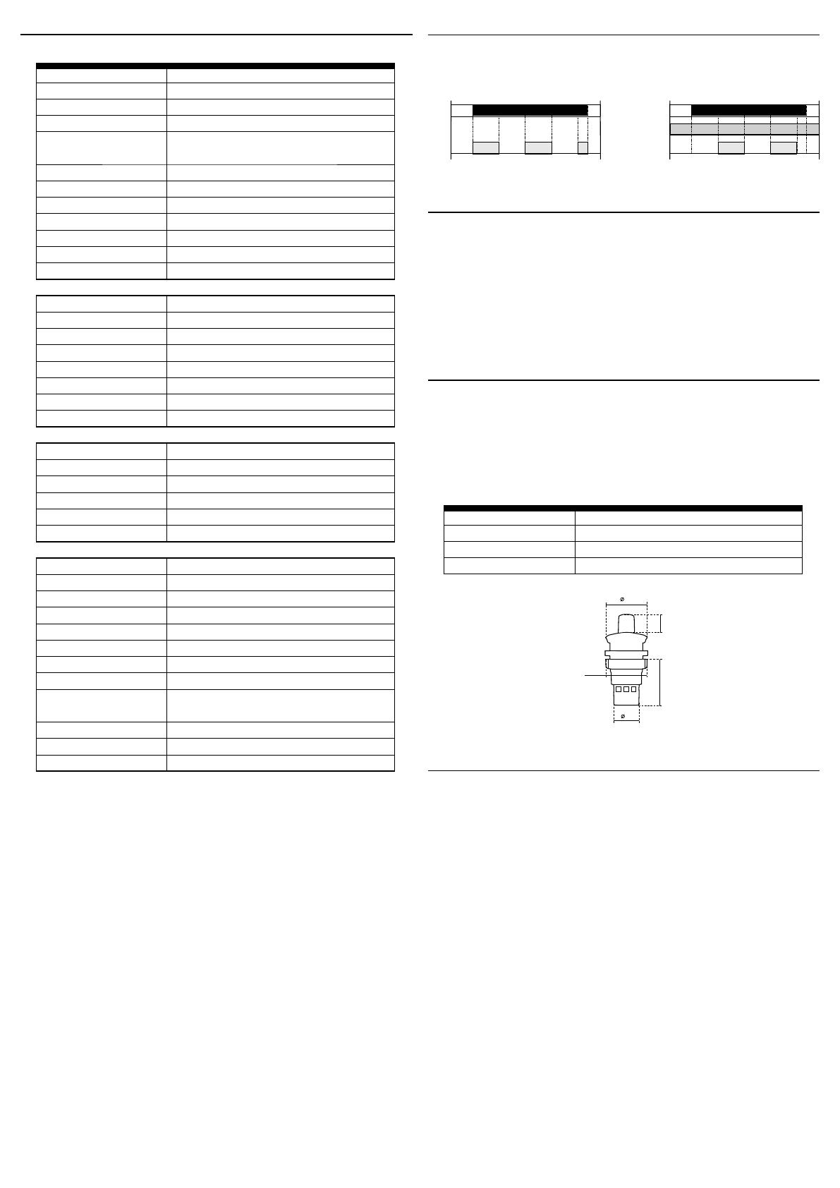
Cycler beggining with pulse Cycler beggining with pause
More accurate setting of timing for long periods of time
Example of time setting to 8 hours period:
For rough setting use time scale 1 - 10 s on the potentiomenter.
On the external potentiometer for ne adjustment of time to adjust 8 s, check accuracy
(eg. a stopwatch).
On rough time setting, set potentiometer to originally desired scale 1 - 10 hours, leave
a ne setting as it is.
Potentiometer
It is possible to connect the external operating potentiometer up to the distance of
maximally 10 meters (32.8 ft.) from relay CRM-2HE, for example in switchboard. The external
potentiometer has cover IP65 from the front side and IP20 from the rear side. It is absolutelly
necessary to connect potentiometer with the device in correct way. The terminals on the
device must be connected to the equally marked terminal on the potentiometer.
Potentiometer:
Protection degree:
Max. cable size (mm2):
Weight:
10-150 kΩ, linear
IP65 from front side / IP20 from back side
1.5 with sleeve / without sleeve max. 2.5 (AWG 12)
16 g (0.6 oz.)


