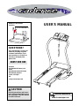
Weslo Cadence 630 treadmill combines advanced technology with innovative design to help you enjoy an excellent cardiovascular workout at home. It features a powerful motor and a spacious running belt, allowing you to walk, jog, or run at your desired pace. With its adjustable incline, you can increase the intensity of your workouts. The console provides easy-to-use controls and a display that tracks your progress, including speed, distance, time, and calories burned. Safety features include a sturdy frame, handrails, and a safety key.
Weslo Cadence 630 treadmill combines advanced technology with innovative design to help you enjoy an excellent cardiovascular workout at home. It features a powerful motor and a spacious running belt, allowing you to walk, jog, or run at your desired pace. With its adjustable incline, you can increase the intensity of your workouts. The console provides easy-to-use controls and a display that tracks your progress, including speed, distance, time, and calories burned. Safety features include a sturdy frame, handrails, and a safety key.


-
 1
1
-
 2
2
-
 3
3
-
 4
4
-
 5
5
-
 6
6
-
 7
7
-
 8
8
-
 9
9
-
 10
10
-
 11
11
-
 12
12
-
 13
13
-
 14
14
-
 15
15
-
 16
16
-
 17
17
-
 18
18
-
 19
19


Weslo Cadence 630 treadmill combines advanced technology with innovative design to help you enjoy an excellent cardiovascular workout at home. It features a powerful motor and a spacious running belt, allowing you to walk, jog, or run at your desired pace. With its adjustable incline, you can increase the intensity of your workouts. The console provides easy-to-use controls and a display that tracks your progress, including speed, distance, time, and calories burned. Safety features include a sturdy frame, handrails, and a safety key.
Ask a question and I''ll find the answer in the document
Finding information in a document is now easier with AI
Related papers
-
Weslo WETL21021 User manual
-
-
-
-
-
-
-
-
-
Other documents
-
ProForm PETL5051 Owner's manual
-
-
-
Pro-Form 385EX PETL38590 User manual
-
-
-
-
-
-