Page is loading ...

OWNER
’
S OPERATION AND INSTALLATION MANUAL
This appliance may be installed in an aftermarket*,
permanently located manufactured (mobile) home,
where not prohibited by local codes.
This appliance is only for use with the type of gas
indicated on the rating plate. This appliance is not
convertible for use with other gases.
* Aftermarket: Completion of sale, not for purpose of resale,
from the manufacturer.
Consumer : Please retain these
instruction for future use.
Do not store or use gasoline or other flammable
vapors and liquids in the vicinity of this or any
other appliance.
WHAT TO DO IF YOU SMELL GAS
Do not try to light any appliance.
Do not touch any electrical switch; do not use
any phone in your building.
Immediately call your gas supplier from a
neighbor’s phone. Follow the gas supplier’s
instructions.
If you cannot reach your gas supplier, call the
fire department.
Installation and service must be performed by
a qual
ified installer, service agency, or local
gas supplier.
WATER VAPOR: A BY-PRODUCT OF UNVENTED
RO
OM HEATERS
Water vapor is a by-product of gas combustion. An
unvented room heater produces approximately one
(1) ounce (30)ml of water for every 1,000BTU’S
(.3KW’S) OF gas input per hour, Refer to page 7.
Installer: Please leave these instructions
with the consumer.
WARNING: If the information in this
manual is not followed exactly, a fire or ex-
plos i o n ma y re sul t causing property
damage, personal injury, or loss of life.
YELLOW FLAME
VENT-FREE GAS LOG
HEATER
WZN(L)18TLA
WZN(L)24TLA
WZN(L)30TLA
WZN(L)18HLA
WZN(L)24HLA
WZN(L)30HLA
WZN(L)18MVA
WZN(L)24MVA
WZN(L)30MVA
Table of Contents
Important Safety Information……………….…...…...2
Product features……………………………………....3
Fresh Air For Combustion And Ventilation.………....4
Determining Fresh-air Flow For Heater Location…..4
Installation…………………………………………... ..9
Checking Gas Connections……………………….....11
Installing Logs…………………………………….
..….13
Operating Instructions… ……….…... ………....…...15
Cleaning And Maintenance……………………. …...18
Troubleshooting………………………………....…….21
Parts List……………………………………….......… 24
WARNING: This is an unvented gas-
fired heater. It uses air (oxygen) from the
room in which it is installed. Provisions
for adequate combustion and ventilation
air must be provided. Refer to Air For
Combustion and Ventilation section on
page 4 of this manual.
Questions about installation, operation, or troubleshooting? Before returning to your retailer, call
customer service department toll-free at (877)886-5989.
PC-WZL014-01-1301
•
•
•
•

IMPORTANT SAFETY
INFORMATION
IMPORTANT: Read this owner’s
manual carefully and completely
before trying to assemble, operate,
or servicethis heater.Improper use
of this heater can cause serious in-
jury or death from burns, fire,
explosion, electrical shock, and
carbon monoxide poisoning.
WARNINGS
Carbon Monoxide Poisoning:
Early signs of carbon monoxide poi-
soning resemble the flu, with
headaches, dizziness, or nausea. If
you have these signs, the heater may
not be working properly.
Get fresh air immediately!
Have heater serviced. Some people
are more affected by carbon monox-
ide than others. These include preg-
nant women, persons with heart or
lung disease or anemia, those under
the influence of alcohol, and those at
high altitudes.
Natural or propane/LP Gas:
Natural or propane/LP gas is odorless.
An odor-making agent is added to
natural or propane/LP gas. The odor
helps you detect a natural or propane/
LP gas leak. However, the odor added
to natural or propane/LP gas can fade.
Natural or propane/LP gas may be
present even though no odor exists.
WARNING: Do not use any ac-
cessory not approved for use with
this log set.
WARNING: Any change to
this heater or its controls can be
dangerous.
Do not place clothing or other
flammable material on or near the
appliance. In or on the fireplace.
Models are equipped for Natural
gas. Field conversion is not
permitted.
Models are equipped for propane
gas. Field conversion is not
permitted.
WARNING
Due to high temperatures, heater
should be located out of traffic and
away from furniture and draperies.
Surface of heater becomes veryhot
while runningheater. Keep children
and adults away from the hot sur-
face to avoid burns or clothing
ignition. Heater will remain hot for
a short time after shut off. Allow
surface to cool before touching.
Carefullysupervise young children
when they are in the same room
with the heater
Make sure a fireplace screen is in
place before running thelog set. Do
not install in bedrooms or
bathrooms.
Keep the appliance area clear and
free from combustible materials,
gasoline, and other flammable va-
pors and liquids.
1. This appliance is only for use with the
typeof gas indicatedon therating plate.
This appliance is not convertible for use
with other gases.
2. Do not place natural or propane/LP
supply tank(s) inside any structure.
Locate natural or propane/LP supply
tank(s) outdoors.
3. To prevent performance problems,
Propane/LP tank of less than 100 lbs.
capacity is not recommended.
4. If you smell gas
shut off gas supply.
do not try to light any appliance.
do not touch any electrical
switches, do not use any phones
in your building.
immediately call your gas
supplier from a neighbor
’s
phone. Follow the gas supplier’s
instructions.
if you cannot reach your gas
supplier, call the fire department
5. This heater shall not be installed in a
bedroom or bathroom unless installed
as a vented appliances.
6.This heater needs fresh, outside air
ventilationto runproperly. Thisheaterhas
an Oxygen Depletion Sensor (ODS)
safety shutoff system. The ODS shuts
down the heater if not enough fresh air is
available.(See FreshAir For Combustion
And Ventilation, pages 4 through 6).
7. Do not run heater
where flammable liquids or
vapors are used or stored.
under
dusty conditions.
8
. Before using furniture polish, wax,
carpet cleaner, or similar products,
turn heater off. If heated, the vapors
from these products may create a white
powder residue within burner box or
on adjacent walls and furniture.
9. Before installing in a solid fuel burning
fireplace, the chimney flue and firebox
and loose paint by a qualified chimney
cleaner. Creosote will ignite if heated.
Inspect chimney flue for damage.
10. Do not use heater if any part has
been under water. Immediately call a
qualified service technician to inspect
the ro
om heater and to replace any part
o
f the control system, and any gas
control, which has been under water.
11. Turn off and let cool before
servicing. Only a qualified service
person should service and repair
heater.
12. Operating heater above elevations
of 4,500 feet could cause pilot outage.
13. If fireplace has glass doors, never
operate this heater with glass doors
closed. If you operate heater with doors
closed, heat buildup inside fireplace will
cause glass to burst. If fireplace
opening has vents at the bottom, you
must open the vents before always
operate heater with glass doors.fully
open.
14.Thi
s log heater is designed to be
smokeless. If logs ever appear to be
smoking, turn off heater and call a quali-
fied service person. NOTE: During initial
operating, slightsmokingcould occurdue
to log curing and heater burning manu-
facturing residues.
15. To prevent the creation of soot, follow
the instructions in Cleaning and Mainte-
nance (pages19 and 20).
2
must be cleanedof soot, creosote, ashes
•
•
•
•
•
•
•

16.Solid-fuelsshallnotbeburnedina fireplaceinwhich
an unvented room from heater is installed.
State of Massachusetts: The installation must
bemadebya licensedplumberorgasfitterintheCom-
monwealth of Massachusetts.
Sellers of unvented propane or natural gas-fired
supplemental room heaters shall provide to each pur-
chaser a copy of 527 CMR 30 upon sale of the unit.
In the state of Massachusetts, unvented propane or
nature gas-fired space heaters shall be prohibited in
bedrooms and bathrooms.
PRODUCT FEATURES
OPERATION
SAFETY PILOT
This heater has a pilot with an Oxygen Depletion Sen-
sor (ODS) safety shutoff system. The ODS/pilot shuts
off the heater if there is not enough fresh air.
PIEZO IGNITION SYSTEM
This heater is equipped with a piezo ignitor. This sys-
tem requires no matches, batteries, or other sources
to light heater.
This heater is clean burning. It requires no outside
venting. There is no heat loss out of a vent or up a
chimney. Heat is generated by realistic, dancing yellow
flames. This heater is designed for ven
t-free operation
w
ithfluedamper closed.Ithasbeentestedand approved
toANSI Z21.2 standard for unvented heaters. State and
local codes in some areas prohibit the use of vent-free
heaters.
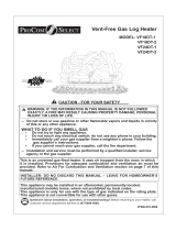
PRODUCT IDENTIFICATION
Figure1-Yellow Flame Vent-Free Gas Logs
Heater(Logs May Vary By Model)
CAUTION: Do not remove the metal data
plates from the grate assembly. The Data plates
contain important product information.
lnstall and use heater with care. Follow all local codes. In the
absence of local codes, use the latest edition of The Na-
tional Fuel Gas Code, ANSZ 223.1, also known
as NFPA 54*. *Available from:
American National Standards
lnstitute, lnc.
1430 Broadway
New York, NY 10018
National Fire Protection Association, lnc.
Batterymarch Park
Quincy. MA 02269
LOCAL CODES
1. Remove logs and heater base assembly from carton.
Note: Do not pick up heater base assembly by burners.
This could damage heater. Always handle base assem-
bly by grate.
2. Remove all protective pa
ckaging app
lied to logs and
heater for shipment.
3. Check all items for any shipping damage. If
damaged, promptly inform dealer where you pur
chased the heater from.
UNPACKING
WATER VAPOR: A BY-PRODUCT OF UNVENTED ROOM HEATERS
Water vapor is a by-product of gas combustion. An
unvented room heater produces approximately one(1)
ounce(30ml) of water for every 1,000BTU’s(.3KW’s) of
gas input per hour.
Unventedroomheatersarerecommendedassupplemen-
tal heat (a room) rather than a primary heat source (an
entire house). In most supplem
ental heat application, the
water vapor does not create a problem. In most
applications, the water vapor enhances the low humidity
atmosphere experience during cold weather.
The following steps will help insure that water vapor does not
become a problem.
1. Be sure the heater is sized properly for the application,
including ample combusion air and circulation air.
2. If high humidityis experienced, a dehumidifier may beused
to help lower the water vapor content of the air.
3. Do not use an unvented room heater as the pr
imary heat
source.
3

FRESH AIR FOR
COMBUSTION AND
VENTILATION
Today’s homes are built more energy ef-
ficient than ever. New materials, in-
creased insulation, and new construction
methods help reduce heat loss in homes.
Home owners weather strip and caulk
around windows and doors to keep the
cold air out and the warm air in. During
heating months, home owners want their
homes as airtight as possible.
While it is good to make your home en-
ergy efficie
nt, your home needs to
breathe
. Fresh air must enter your home.
All fuel-burning appliances need fresh air
for proper combustion and ventilation.
Exhaust fans, fireplaces, clothes dryers,
and fuel burning appliances draw air from
the house. To operate you must provide
adequate fresh air for these appliances.
This will insure proper venting of vented
fuel-burning appliances.
PRODUCING ADEQUATE
VENTILATION
All spaces in homes fall into one of
the three following ventilation
class
ifications:
1. Unusually Tight Construction
2. Unconfined Space
3. Confined Space
The information on pages 4 through 6
will help you classify your space and
provide adequate ventilation.
Unusually Tight Construction
The air that leaks around doors and win-
dows may provide enough fresh air for
combustion and ventilation. However,
in buildings of unusually tight
construction, you must provide addi-
tional fresh air.
Unusually tight construction
is defined as construction
wher
e:
a. walls and ceilings exposed to the out-
side atmosphere have a continuous wa-
ter vapor retarder with a rating of one
perm (6 x 10
-11
kg per pa-sec-m
2
) or less
with openings gasketed or sealed and
b. whether stripping has been added on
windows that can opened and doors.
c. caulking or sealants are applied to
areas such as joints around window and
door frames, between sole plates and
floors, between wall-ceiling joints, be-
tween wall panels, at penetrations for
plumbing, electrical, and gas lines,and
at othe
r openings.
If your home meets all of the three
criteria above, you must provide addi-
tional fresh air. See Ventilation Air From
Outdoors, pages 5 and 6.
If your home does not meet all of the
three criteria above, see Determining
Fresh-Air Flow for Heater Location.
DETERMINING FRESH-AIR FLOW FOR HEATER LOCATION
Determining if You Have a Confined or Unconfined Space *
Use this worksheet to determine if you have a confined or unconfined space.
Spac
e: Includes the room in which you will install heater plus any adjoining rooms with doorless passage
ways or ventilation grills between the rooms.
1. Determine the volume of the space (length x width x height).
Length x Width x Height = ___________________ cu. ft. (volume of space)
Example: Space size20ft. (length) x 16ft(width) x 8ft.(ceiling height)=2560cu.ft.(volume of space)
4
or ventilation grills between them.
only if there are doorless passageways
*Adjoining rooms are communicating
ventilation air.
provided for adequate combustion and
construction unless provisions are
a confined space or unusually tight
This heater shall not be installed in
doors, are considered a part of the
through openings not furnished with
in which the appliances are installed*,
communicating directly with the space
pliances installed in that space. Rooms
of the aggregate input rating of all ap-
3
per 1,000 Btu per hour (4.8 m per kw)
volume is not less than 50 cubic feet
ances installed in that space and an
the aggregate input rating of all appli-
3
1,000 Btu per hour (4.8 m per kw) of
Confined space is a space whose
volume is less than 50 cubic feet per
does not meet the required
volume for indoor combustion air,
combustion and ventilation air
shall be provided by one of the
methods described in the National
F u e l G a s C o d e , A N S I
Z 2 2 3 . 1 / N F P A 5 4 , t h e
International Fuel Gas Code, or
a p p l i c a b l e l o c a l c o d e s.
which
the heater may be operated
WARNING:
If the area in
unconfined space as a space whose
unconfined space.

If additional ventilation to adjoining room is supplied with grills or openings, add the volume of these rooms to the total
volume of the space.
2. Divide the space volume by 50 cubic feet to determine the maximum Btu/Hr the space can support.
_________________ ( volume of space) ÷ 50 cu. ft. = (Maximum Btu/Hr the space can support)
Example: 2560 cu. ft. (volume of space) ÷ 50 cu. ft. = 51.2 or 51,200 (maximum Btu/Hr the space can support)
3. Add the Btu/Hr of all fuel burning appliances in the space.
Vent-free heater __________________ Btu/Hr
Gas water heater* __________________Btu/Hr Example:
Gas furnace __________________Btu/Hr Gas water heater 40,000 Btu/Hr
Vented gas heater __________________Btu/Hr Vent-free heater + 31,500 Btu/Hr
Gas Fireplace logs __________________Btu/Hr Total = 71,500 Btu/Hr
Other gas appliances* +_________________ Btu/Hr
Total =__________________Btu/Hr
* Do not include direct-vent gas appliances. Direct-vent draws combustion air from the outdoors and vents to
the outdoors.
4. Compare the maximum Btu/Hr the space can support with the actual amount of Btu/Hr used.
.___________Btu/Hr (maximum the space can support)
___________Btu/Hr (actual amount of Btu/Hr used)
Example: 51,200 Btu/Hr (maximum the space can support)
71,500 Btu/Hr (actual amount of Btu/Hr used)
The space in the above example is a confined space because the actual Btu/Hr used is more than the maximum Btu/Hr the
space can support. You must provide additional fresh air. Your options are as follows:
A. Rework worksheet, adding the space of an adjoining room. If the extra space provides an unconfined space,remove
door to adjoining room or add ventilation grills between rooms.See Ventilation Air From Outdoors, page 6.
B. Vent room directly to the outdoors. See Ventilation Air From Outdoors, page 6.
C. Install a lower Btu/Hr heater, if lower Btu/Hr size makes room unconfined.
If the actual Btu/Hr used is less than the maximum Btu/Hr the space can support, the space is an unconfined space. You will
need no additional fresh air ventilation.
WARNING: If the area in which the heater may be operated is smaller than that de-
fined as an unconfined space or if the building is of unusually tight construction, provide
adequate combustion and ventilation air by one of the methods described in the National
Fuel Gas Code, ANS Z223.1, Section 5.3 or applicable local codes.
Ventilation Air From Inside Building
This fresh air would come from adjoining unconfined space. When ventilating to an adjoining unconfined space, you
must provide two permanent openings:
one within 12" of the wall connecting the two spaces (see options 1 and 2, Figure 2). You can also remove door into
adjoining room (see option 3, Figure 2). Follow the National Fuel Gas Code NFPA 54/ANS Z223.1. Section 5.3, Air for
Combustion and Ventilation for required size of ventilation grills or ducts.
5

Figure 2-Ventilation Air from Inside Building
Ventilation Air From Outdoors
Provide extra fresh air by using
ventilation grills or duct. You must
provide two permanent openings:
one within 12" of the ceiling and
one within 12" of the floor.
Connect these items directly to the
outdoors or spaces open to the
outdoors. These spaces include
attics and crawl spaces. Follow the
National Fuel Gas Code NFPA 54/
ANS Z223.1, Section 5.3. Air for
Combustion and Ventilation for re-
quired size of ventilation grills or
ducts.
IMPORTANT: Do not provide
openings for inlet or outlet air into
attic if attic has a thermostat-con-
trolled power vent. Heated air en-
tering the attic will activate the
power vent.
WARNING: Rework worksheet,
adding the space of the adjoining
unconfined space. The combined
spaces must have enough fresh
air to supply all appliances in both
spaces.
NOTICE: This heater is intended
for use as supplemental heat. Use
this heater along with your pri-
mary heating system. Do not in-
stall this heater as your primary
heat source. If you have a central
heating system you may run the
system’s circulating blower while
using the heater. This will help cir-
culate the heat throughout the
house. In the event of power
outage, you can use this heater as
your primary heat source.
WARNING: A qualified ser-
vice person must install heater.
Follow all local codes.
NOTICE: State or local codes
may only allow operation of
this appliance in a vented
configuration. Check your
state or local codes.
CAUTION: This heater cre-
ates warm air currents. These
currents move heat to wall sur-
face next to heater. Installing
heater next to vinyl or cloth wall
coverings or operating heater
where impurities (such as to-
bacco smoke, aromatic
candles, cleaning fluids, oil or
kerosene lamps, etc.) in the air
exist may discolor walls.
WARNING: Before installing
in a solid flue burning firebox,
the chimney flue and firebox
must be cleaned of soot,
creosote, ashes and loose paint
by qualified chimney cleaner.
Creosote will ignite if highly
heated. A dirty chimney flue
may create and distribute soot
within the house. Inspect chim-
ney flue for damaged.
WARNING: Seal any fresh air
vents or ash clean-out doors lo-
cate on the floor or wall of
fireplace. If not, drafting may
cause pilot outage or sooting.
Use a heat resistant sealant. Do
not seal chimney flue damper.
IMPORTANT: Vent-free heaters add
moisture to the air. Although this is
beneficial, installing heater in rooms
without enough ventilation air may cause
mildew to form from too much moisture.
See Air for Combustion and Ventilation,
pages 4 through 5.
CHECK GAS TYPE
Use only natural or propane/LP gas. If
supply is not natural or propane/LP, do
not install heater. Call dealer where you
purchased heater from for proper gas
type.
WARNING: Maintain the Mini-
mum clearances. If you can pro-
vide greater clearances from the
floor, ceiling, and adjoining wall.
Minimum Fireplace Clearance
to Combustible Materials
Log size side wall ceiling
18",24",30” 16" 42"
6

Log Log sizing requirements
size Minimum Firebox Size
High Depth Front WidthRear Width
18" 20" 14” 29" 23"
24" 20.4" 14" 34" 25.4"
30" 20.4" 14" 39" 31.4"
Minimum Clearance For Side
Combustible Material, Side Wall, and
Ceiling.
A. Clearance from the side of the fireplace open
ing to any combustible material and wall should
follow diagram in Figure4.
B. Clearance from the top of the fireplace opening
to the ceiling should not be less than 42 inches.
Minimum Noncombustible
Material Clearance
If Not Using Mantel
You must have noncombustible
material(s) above the fireplace
opening. Noncombustible
materials (such as slate, marble
tile, etc.) must be at least 1/2 inch thick. With
sheet metal, you must have noncombustible
material behind it. Noncombustible fireplace hood
accessory. See figure 5 at right for minimum clear-
ance requirements.
Figure 4-Minimum Clearance
for Combustible to Wall
NOTICE: This heater may be
used as a vented product If so,
you must always run heater
with chimney flue damper
open. If running heater with
damper open, noncombustible
material above fireplace open-
ing is not needed. Go to Install-
ing Damper Clamp Accessory
for Vented Operation, page 9
If Using Mantel
You must have noncombustible
material(s) (such as slate, marble, tile,
etc). at least 1/2 inch thick. With sheet
metal, you must have noncombustible
material behind it. Noncombustible
material must extend at least 8 inches
up. If noncombustible material is less
than 12”, you must install the fireplace
hood accessory. Even if noncombus-
tible material is more
han 12”, you may need the hood
accessory to deflect heat away
from mantel shelf. See figures
5,6 and 7 for minimum clear-
ances requirements.
IMPORTANT: If you do not
meet these minimum
clearances, you must operate
heater with chimney flue
damper open. Go to Installing
Damper Clamp Accessory For
Vented Operation (page 9).
MANTEL CLEAR-
ANCES
In addition to meeting noncom-
bustible material clearances,
you must also meet required
clearances between fireplace
opening and mantel shelf. If you
do not meet the clearances
listed below, you will need a
hood.
Noncombustible Requirements for
Material Distance(A) Safe Installation
12" or more
Between 8"and 12"
less than 8"
Noncombustible material okay.
24”.30” Model: Install fireplace hood
accessory 18” Model: Noncombus-
tible material okay.
Noncombustible material must be
extended to at least 8".See Be-
tween 8"and 12" above. If you
can not extend material, you must
operate heater with flue damper
open.
Figure 5 - Heat Resistant Material (slate, marble, tile,
etc. ) Above Fireplace
7

Determining Mantel Clearances
If you meet minimum clearance requiments
between mantel shelf and top of fireplace
opening, a hood is not necessory (see Figure
6).
Determining Minimum Mantel Clearance
When Using a Hood
If minimum clearances in figure 6 are not meet,
you must have a hood. When using a hood there
are still certain minimum mantel clearances
required. Follow minimum clearances shown in
Figure 7 when using a hood.
NOTICE: Surface temperature of adjacent
walls and mantels become hot during
operation. Walls and mantels above the
firebox may become too hot to touch. If
installed properly, these temperatures
meet the requirement of the national prod-
uct standard. Follow all minimum clear-
ances shown in this manual.
NOTICE: If your installation does not meet
the minimum clearances shown, you must
do one of the following:
Operate the logs only with the flue
damper open.
Raise the mantel to an acceptable height.
l
l
FLOOR CLEARANCES
A. If installing appliance on the floor level,
you must maintain the minimum distance
of 14” to combustibles (see Figure 8).
B. If combustible materials are less than
14” to the fireplace, you must install ap
pliance at least 5” above the combus
tible flooring (see Figure 9 ).
Figure 6 - Minimum Mantel Clearances Without
Using Hood
Figure 7 - Minimum Mantel Clearances When
Using Hood
Figure 8- Minimum Fireplace
Clearances if Installed at Floor
Level
Figure 9 - Minimum Fireplace
Clearances Above Combustible Flooring
8

INSTALLING DAMPER CLAMP AC-
CESSORY FOR VENTED OPERATION
NOTE: When used as a vented heater,
appliance must be installed only in a
solid-fuel burning fireplace with a work-
ing flue constructed of noncombustible
material. You may use this heater as a
vented product. There are three reasons
for operating your
Heateras a vented model:
1. The fireplace does not meet the
clearances to combustible require-
ments for vent-free operation.
2. State or local codes do not permit
vent-free operation.
3. You prefer vented operation.
INSTALLATION
If reasons number 1 or 2 above apply
to you, you must permanently open
chimney flue damper. You must install
thedamper not clamp accessory (not
provided) This will insure vented opera-
tion (see Figure 10). The damper clamp
will keep damper open. Installation in-
structions are included with not clamp
accessory.
See chart below for the minimum per-
manent flue opening you must provide.
Attach damper not clamp so the mini-
mum permanent at all opening will be
maintained at all times.
Figure 10- Attach Damper Fireplace
INSTALLING HEATER BASE
ASSEMBLY
CAUTION: Do not remove
the metal data plates at-
tached to the heater base
assembly. The data plates
contain important warranty
Information.
WARNING:You must se-
cure this heater to fireplace
floor. If not, heater will move
when you adjust controls.
Moving heater may cause a
leak.
Chimney Minimum Permanent
Height (ft.) Flue Opening (sq. Ins.)
6' to 15' 39 sq inches
15' to 30' 29 sq inches
Area of Various Standard
Round Flues
Diameter (ins.)Area (sq. ins.)
5" 20 sq inches
6" 29 sq inches
7" 39 sq inches
8" 51 sq inches
WARNING: If installing in a
sunken fireplace, special care
is needed You must raise the
fireplace floor to allow access
to heater control panel. This
will insure adequate air flow
and guard against sooting.
Raise fireplace floor with non-
combustible material.
CAUTION: Do not pick up
heater base assembly by the
burner. This could damage
heater. Only handle base as-
sembly by grates.
thermostat bulb. Avoid nicks or
sharp bends in thermostat bulb
wire. Keep thermostat bulb in
mounting bracket.
INSTALLATION ITEMS
NEEDED
l Hardware package (provided
with heater).
l Approved flexible gas hose
(not provided) if allowed by
local codes.
l Sealant (resistant to natural
or propane/LP gas, not
provided).
l Electric dril.l with 3/16” drill bit.
l Philips screwdriver.
1. Apply pipe joint sealant lightly to
make threads to be threaded into
gas regulator. Connect approved
flexible gas hose to gas regulator
of heater (see Figure 11).
IMPORTANT: Make sure the
heater burners are level. If heater
is not level, heater will not work
properly. Avoid damage to
Figure 11 - Attaching Flexible
Gas Hose to Heater Gas
Regulator
9

IMPORTANT :Hold gas regulatorwith
wrench when connecting flexible gas
hose
2. Locate masonry screws in hard-
ware package.
3. Position heater base assembly in
fireplace.
4. Place logs in their proper position
on heater base.
5. Centerheaterbaseandlogsfront-
to-front and side-to-side in
fireplace.
6. Carefully remove logs without
moving heater base.
7. Mark screw locations through
holes in mounting brackets (see
Figure 12). If installing in a brick-
bottom fireplace, mark screw lo-
cations in mortar joint of bricks.
8. Remove heater base from
firep
lace.
9. Drill holes at marked locations
using 3/16” drill bit.
10. Attach base assembly to
fireplace floor using two masonry
screws (in hardware package)
(see Figure 12).
CONNECTING TO GAS
SUPPLY
WARNING: A qualified ser-
vice person must connect
heaterto gassupply. Follow all
local codes.
WARNING: This appliance
requires 1/2” NPT (National Pipe
Thread) inlet connection to the
pressure regulator.
WARNING: Never connect
heater to private( non- utility)
gas wells. This is commomly
known as well head gas.
CAUTION: Never connect
heater directly to the natural or
propane/LP supply. This heater
requires an external regulator
(not supplied). Install the exter-
nal regulator between the
heater and natural or propane/
LP supply.
INSTALLATION ITEMS
NEEDED
Beforeinstallingheater, makesure
you have the items listed below
external regulator (supplied by
installer)
piping (check local codes)
sealant (resistant to natural or
propane/LP gas)
equipment shutoff valve
test gauge connection
sediment trap
tee joint
pipe wrenc
Figure 12- Attaching Heater
Base to Fireplace Floor
A CSA/AGA design-certified equip-
ment shutoff valve with 1/8" NPT tap
is an acceptable alternative to test
gauge connection. Purchase the op-
tional CSA/AGA design-certified
equipment shutoff valve from your
deale
r.
The in
staller must supply an
external regulator. The external
regulator will reduce incoming
gas pressure. You must reduce
incominggaspressuretobetween11
and 14 inches of water. If you do not
reduce incoming gas pressure ,
heater regulator
damage could occur. Install external
regulator with the vent down as
shownin Figure 13. Pointing thevent
down protects it from freezing rain or
sleet.
Installation must include equip-
ment shutoff valve, union, and
plugged 1/8" NPT tap. Locate
NPT tap within reach for test
gauge hook up.NPT tap mus
t be
upstream from heater (see Fi
g-
ure 14).
IMPORTANT: Install an equipment
shutoff valve in an accessible
location. The equipment shutoff
valve is for turning on or shutting off
the gas to the appliance.Apply pipe
joint sealant lightly to male threads.
This willpreventexcesssealantfrom
going into pipe. Excess sealant in
pipe could result in clogged heater
valves.
CAUTION: Only use a new,
black iron or steel pipe. Inter-
nally-tinned copper tubing may
be used in certain areas. Check
your local codes. Use pipe of
large enough diamete
r to al
low
proper gas volume to heater. If
pipe is too small, undue loss of
pressure will occur.
CAUTION: Use pipe joint
sealant that is resistant to natu-
ral gas(NG) or liquid petroleum
(LP) gas.
Figure 13-A-External
Regulator with Vent Pointing
Down For NG
Figure 13-B-External
Regulator with Vent Pointing
Down For LP
10
•
•
•
•
•
•
•
•

We recommend that you install sedi-
ment trap in the supply line as shown
in Figure 14. Locate sediment trap
where it is within reach for cleaning.
Locate sediment trap where trapped
matter is not likely to freeze. A sedi-
ment trap traps moisture and
contaminants. This keeps them from
going into heater controls. If sediment
trap is not installed or is installed
incorrectly, heater may not run
properly.
IMPORTANT: Hold pressure regula-
tor with wrench when connecting it to
gas piping and/or fittings.
CHECKING GAS
CONNECTIONS
WARNING: Test all gas piping
and connections for leaks after
installing or servicing. Correct all
leaks at once.
WARNING: Never use an open
flame to check for leaks. Apply a
mixture of liquid soap and water
to all joints. Bubbles forming
show a leak. Correct all leaks
immediately. Press Testing Gas
Supply Piping System.
Prss Testing Gas Supply Pip-
ing System
Test Pressure in Excess Of 1/2
PSIQ (3.5 K Pa)
1. Disconnect appliance with its
appliance main gas valve (control
valve) and equipment shutoff valve
from gas supply piping system.
Pressure in excess of 1/2 psig will
damage heater regulator.
2. Cap off open end of gas pipe where
equipment shutoff valve was
connected.
3. Pressurize supply piping system by
either using compressed air or
opening main gas valve located on
or near gas tank .
4. Check all joints of gas supply pip-
ing system. Apply a mixture of liq-
uid soap and water to gas joints.
bubbles forming show a leak.
5. Correct all leaks immediately.
6. Reconnect heater and equipment
shutoff valve to gas supply. Check
reconnected Fittings for leaks.
Test Pressures Equal To or Less
Than 1/2 PSIQ (3.5 K Pa)
1. Close equipment shutoff valve (see
Figure 15).
2. Pressurize supply piping system by
either using compressed air or
opening main gas valve located on
or near gas supply tank.
3. Check all joints from gas tank to
equipment shutoff valve (see Fig-
ure 16). Apply mixture of liquid soap
and water to gas joints. Bubbles
forming show a leak.
4. Correct all leaks immediately.
Figure 14 - Gas Connection
Figure 15- Equipment
Shutoff Valve
Figure 16-A Checking Gas Joints for NG
Pressure Testing Heater
Gas Connections
1. Open equipment shutoff valve
(see Figure 15).
2. Open main gas valve located
on or near gas tank .
3. Make sure control knob of
heater is in the OFF position.
4. Check all joints from equipment
shutoff valve to control valve
(see Figure 16). Apply mixture
of liquid soap and water to gas
joints. Bubbles forming show a
leak.
5. Correct all leaks immediately.
6 Light heater (see Operating
Instructions, page 16-page 19).
Check the rest of the internal
joints for leaks.
7. Turn off heater (see To Turn Off
Gas to Appliance, page 17).
11

Figure 16-B Checking Gas joints For LP
ELECTRICAL WIRING (MILLIVOLT)
The millivolt valve is a self-pow-
ered combination gas control THAT
DOES NOT REQUIRE 110 VAC TO
OPERATE.
MILLIVOLT CONTROL
The valve regulator controls the
burner pressure which should be
checked at the pressure test point.
Turn captured screw counter clock-
Figure 17 - Wiring Diagram
wise two or three turns and then
place tubing to pressure gauge
over test point (Use test point
“OUT” closest to control knob).
After taking pressure reading, be
sure and turn captured screw
clockwise firmly to re-seal. Do not
over torque. Check for gas leaks.
It is very important to install
the logs exactly as
instructed. Do not modify
logs. Only use logs supplied
with heater
.
CAUTION: Label all wires
prior to disconnection when ser-
vicing controls. Wi r ing er rors
can cause improper and danger-
ous operation. Verify proper op-
eration after servicing.
CAUTION: After installa-
tion and periodically thereafter,
check to ensure that no yellow
flame comes in contact with any
log. With the heater set to High,
check to see if yellow flames
contact any log. If so, reposition
logs according to the log instal-
lation instructions in this manual.
Yellow flames contacting logs
will create soot.
WARNING: Failure to position the
parts in accordance with these diagrams
or failure to use only parts specifically ap-
proved with this heater may result in prop-
erty damage or personal injury.
12

CONNECTING REMOTE RECEIVER
THESE INSTRUCTIONS SUPERCEDE THE
SECTION EN-TITLED “HEARTH MOUNT” THE
MILLIVOLT HAND-HELD REMOTE
INSTRUCTIONS SUPPLIED WITH THE
REMOTE.
1. Cut cable to length (approximately 12") for
placement in the fireplace.
2. Strip back 1/4" of the insulation from both ends
of each wire.
3. Connect two .25 female connectors to the wires
at one end of the cable.
4. Insert the opposite ends of the wires into the
receiver wire terminals and tighten the screws.
5. Co
nnect the connectors to the two .25
" male con-
nectors located on the left side when facing the
unit (See Figure 17, page 12). Do not let wire
touch grate or burner.
NOTE: Heat re duces battery life. You can pro-
tect the receiver and extend battery life by
mounting the rec eiver in a wall or other location
outside the fireplace
.
6. Stick velcro pads with self-adhesive backing to bot-
tom of remote receiver and to the left side of the
unit. See Figure 18.
7. Attach remote receiver with velcro pads. Control
switch must face forward.
Figure 18 - Installing Remote
Receiver
Provided Log: 6
Decorative cinders: 1
WARNING: Failure to position the parts in
accordance with these diagrams or failure to
use only parts specifically approved with this
heater may result in property damage or
personal injury.
INSTALLING LOGS
CAUTION: After installation installation and
periodically thereafter, check to ensure that no
flame comes in contact with any log. With the
heater set to high, check to see if flames
contact any log.Ifso,reposition logsaccording
to the log installation instructions in this
manual. Flames contacting logs will create
soot.
Each log is marked with a number. This number will
help you to identify the logs when installing. It is very
important to install these logs exactly as instructed.
Do not modify logs. On
ly use logs supplied with
heate
r.
1. Insert the pins on the back of log #1 into the hole
on the log bracket on the back of grate base,
and tighten the screws (see Figure 19).
13

2. Insert pins on the back of log #2 into the holes on the
log bracket on the middle of grate base. and Tighten
the screws (see Figure 20).
3. Locate log #3 and log #4 over the grate fingers on the
front bracket with the pins on the back of logs sliding
into the holes on the front of the grate base (see Fig-
ure 21 & 22).
4. Place log#5 and log#6on the top of log #1and log #2
by inserting holes on the back of log #5, insert log #6
into the pins on the top of log1, and make sure the
other side of log #6 lines up with the recess of log #3
(see Figure 23 & 24)..
5. Adddecorativecindersa
roundthe gratebaseofheater,
dono
t place anydecorativecinders on logs or burner.
Figure 19-
Figure 20 - Installing Log #
Figure 21- Installing Log #
Figure 22- Installing Log #
3
Figure 23- Installing Log
4
Figure 24-Installing Log
#5
# 6
14
Installing Log #1
2

Avoid any drafts that alter burner flame patterns. Do
not allow fans to blow directly into the fireplace. Do not
place a blower inside the burn area of the firebox. Ceil-
ing fans may create drafts that alter flame patterns. Soot-
ing and improper burning will result.
During manufacturing, fabricating and shipping, various
components of this appliance are treated with certain
oils, films or bonding agents. These chemicals are not
harmful, but may produce annoying smoke and smells
as they are burned off during the initial operation of the
appliance, possibly causing headaches or eye or lung
irritation. This is a normal and temporary occurrence.
The initial break-in operation should last two to three
hours with the burner at the highest setting. Provide
maximum ventilation by opening windows or doors to
allow odors to dissipate. Any odors remaining after this
initial break-in will be slight and will disappear with con-
tinued use.
This appliance must not be used with glass doors in the
closed position. This can lead to pilot outages and se-
vere sooting outside the fireplace.
WARNING: If you do not follow these instructions
exactly, a fire or explosion may result causing property
damage, personal injury or loss of life.
A. This appliance has a pilot which must be lighted by
hand. When lighting the pilot, follow these instruc-
tions exactly.
B. BEFORE LIGHTING smell all around the appliance
area for gas. Be sure to smell next to the floor be-
cause some gases are heavier than air and will settle
on the floor.
WHAT TO DO IF YOU SMELL GAS
l Do not try to light any appliance.
l Do not touch any electrical switches; do not use
any phones in your building.
l Immediately call your gas supplier from a neighbor’s
phone. Follow the gas supplier’s instructions.
l If you cannot reach your gas supplier, call the fire
department.
C. Use only your hand to push in or turn the gas con-
trol knob. Never use tools. If the knob will 8not push
in or turn by hand, don’t try to repair It. Call a quali-
fied service technician or gas supplier. Forced or
attempted repair may result in a fire or explosion.
D. Do not use this appliance if any part has been un-
der water. Immediately call a qualified service tech-
nician to inspect the appliance and to replace any
part of the control system, and any gas control,
which has been under water.
MILLIVOLT CONTROL(MODELS MVA)
LIGHTING INSTRUCTIONS
1. STOP! Read the safety information label.
2. Make sure the manual shutoff valve is fully open.
3. This gas log set is equipped with an ignition de-
vice (piezo) which automatically lights the pilot. If
piezo ignitor does not light the pilot, see instruc-
tions for Match Lighting Instructions, page 18.
4. Turn gas control knob clockwise to the OFF
position, set the thermostat to the lowest setting
and turn ON/OFF switch to OFF position.
5. Wait (5) minutes to clear out any gas. Then smell
for gas, including near the floor. If you smell gas,
STOP!Follow “B” in the safety information label. If
you don’t smell gas, go to next step.
6. From OFF position, turn the gas control knob coun
terclockwise to IGN position. Push in control.
7. With the control knob pushed in, push in and re
lease the piezo ignitor button to light the pilot.
8. Continue pushing the control knob in for a further
60 seconds to prevent the flame detector from
shutting off the gas while the probe is warming up.
Release the control knob.
9. Turn gas control knob counterclockwise to
the ON position.
10. After the pilot has been lit for one minute, the burn-
ers can be turned on. Turn the ON/OFF switch to
ON position or adjust thermostat to desired setting.
11.If the gas logs will not operate, follow the instruc
tions To Turn Off Gas To Appliance below and call
your.
FOR YOUR SAFETY READ BEFORE
LIGHTING
Always operate heater with glass doors fully
open.
OPERATING INSTRUCTIONS
WARNING: Wait 30 seconds before readjusting
the heater when the control knob has been turned
down to a lower setting.
15

Figure 25- Pilot
Figure 26-Control Cover
Plate
TO TURN OFF GAS TO HEATER
1. Turn controlknob clockwise
to OFF position to completelyshut
off the heater.
2. If applicable: Turn ON/OFF switch
to OFF position and/or set thermo-
stat (if present) to lowest setting.
THERMOSTAT (MODELS
TLA) LIGHTING INSTRUC-
TIONS
WARNING:
Iffireplacehasglassdoorsnever
operate this heater with the
glass doors closed. If you op-
erate heater with doors closed,
heatbuildupinside fireplacewill
causeglassto burst.Also,if the
fireplace opening has vents at
the bottom, you must open the
vents before operating heater.
You must operate this heater
with a fireplace screenin place.
Make sure fireplace screen is
closed before running heater.
NOTICE: During initial operation
of newheater, burning logs willgive
off apaper-burningsmell.Anorange
flame will alsobe present.Open the
damper or window to vent smell.
This will only last a few hours.
NOTE: Home owners generally pre-
fer to operate their heater with the
chimneydamper closed. This will put
all the heat into the room. However,
there maybe times you will desire the
full flames of the Hi heat setting but
will find the heat output excessive.
You can open the chimney damper
(if you have one) fully or partially to
release some of the heat.
WARNING: Damperhandle will
be hot if heater hasbeen running.
1. STOP! Read the safety
information.
2. Make sure equipment shutoff
valve is fully open.
3. Press in and turn control knob
clockwise
to the OFF
position.
4. Wait five (5) minutes to clear out
any gas. Then smell for gas, in-
cludingnearthefloor.Ifyousmell
gas, STOP! Follow “B” in the
safety information. If you don’t
smell gas, go to the next step.
5. Slight depress and turn Control
knob counterclockwise
to
thePILOT position.Pressin con-
trolknobforfive(5)seconds(see
Figure 27).
NOTE: You may be running this
heater for the first time after
hooking up to gas supply. If so,
the control knob may need to be
pressed in for 30 seconds. This
willallowairtobleedfrom thegas
system.
6. With control knob pressed in,
press and release ignitor button.
This will light pilot. The pilot is
attached totheburner.Ifneeded,
keep pressing ignitor button. un-
til pilot lights.
.
NOTE: If pilot does not stay
lit, contact a quali
fied service
p
erson or gas supplier for
repairs.
7. Until repairs are made keep
control knob pressed in for
30secondsafterlighting pilot.
After 30 seconds, release
control knob.
NOTE: If pilot goes out, re-
peat steps 3 through 7. This
heater has a safety interlock
system.
If control knob does not pop
out when released, contact a
qualified service person or
gas supplier for repairs.
8. Slightlydepress and turn con-
trol knob counterclockwise
to desired heating
level.Theburnershould light.
Set control knob to any heat
level between HI and LO
CAUTION: Do not try to
adjust heating levels by using
the equipment shutoff valve.
Figure 27-Control Knob and
Ignitor Button Location
Figure 28- Pilot
TO TURN OFF GAS TO
APPLIANCE:
Shutting off heater
Push control knob andturnclock-
wise to OFF position.
Shutting off burners only (pilot
stays lit).
Turn control knob clockwise to
the PILOT position.
16
•
•

5. Push in and turn control knob
counterclockwise to PI-
LOT position. Press in control
knob for five (5) seconds.
Note: You may be running this
heater for the first time after
hooking up to gas supply. If so
you may need to press in con-
trol knob for 30 seconds. This will
allow air to bleed from the gas
system.
6. With control knob pressed in,
push down and release the igni-
tor button. This will light pilot. If
needed, keep pressing ignitor
button until pilot lights.
7. Keep control knob depressed for
ten (10) seconds after lighting
pilot. If pilot goes out, repeat
steps 5,6 and 7.
8. To select the desired heating
level, partially press down the
control knob slightly and rotate
counterclockwise . Re-
lease the downward pressure on
the knob while continuing to turn
until the knob locks at the desired
setting position. Do not operate
between locked positions.
MATCH LIGHTING INSTRUC-
TIONS
1. Remove any items necessary for
easy access to the pilot (for
example: logs, screens, etc.).
2. Follow appropriate lighting instruc-
tions found previously. Instead of
pushing and releasing the piezo
button, light a match and hold the
flame to the end of the pilot and
ignite the pilot.
3. After control knob has been re-
leased and pilot stays lit, reinstall
any items that were removed for
pilot access.
4. Call a qualified service technician
for repair or replacement of the
piezo ignitor.
THERMOSTAT CONTROL OP-
ERATION
The thermostatic control used on
these models differs from standard
thermostats. Standard thermostats
simply turn on and off the burner. The
thermostat used on this heater senses
the room temperature. The thermo-
stat adjusts the amount of gas flow to
the burner. This increases or de-
creases the burner flame height. At
times the room may exceed the set
temperature. If so, the burner will shut
off. The burner will cycle back on when
room temperature drops below the set
temperature. The control knob can be
set to any heat level between HI and
LO. Selecting the HI setting will cause
the burner to remain fully on without
modulating down in most cases.
NOTE: The thermostat sensing bulb
measures the temperature of air near
the heater cabinet. This may not al-
ways agree with room temperature
(depending on housing construction,
installation location, room size, open
air temperatures, etc.), frequent use
of your heater will let you determine
your own comfort levels.
NONTHERMOSTAT
MODELS
LIGHTING INSTRUCTIONS
1. STOP! Read the safety
information, on the side of
heater.
2. Make sure equipment shutoff
valve is fully open.
3. Push in control knob slightly and
turn clockwise to the
OFF position.
4. Wait five minutes to clear out
any gas. Then smell for gas,
including near the floor. If you
smell gas. STOP! Follow “B” in
the safety information on the
side of heater. If you don’t smell
gas, go to the next step.
INSPECTING BURNERS
Check pilot flame pattern and
burner flame patterns often.
PILOT FLAME PATTERN
Figure 29 shows a correct pilot
flame pattern. Figure 30 shows an
incorrect pilot flame pattern. The
incorrect pilot flame is not touch-
ing the thermocouple. This will
cause he thermocouple to cool.
When the thermocouple cools,
the heater will shut down.
If pilot flame pattern is incorrect,
as shown in Figure 30:
l Turn heater off (see To Turn
Off Gas To Appliance).
HLA or TLA MODELS
Figure 29 – Correct Pilot Flame
Pattern
Figure 30 – Incorrect Pilot
Flame Pattern
Millivolt control
Figure 31 – Correct Pilot
Flame Pattern
17

Figure 32– Incorrect Pilot Flame
Pattern
All round burner flame holes
should be open with a small blue
flame present. Some burner
flame holes may become
blocked by debris or rust, with no
flame present. If so, turn off
heater and let cool. Either re-
move the blockage or replace
the burner. Blocked burner flame
holes will create soot.
Figure 33 shows a correct burner
flame pattern. Figure 34 shows an
incorrect burner flame pattern. If
burner flame is incorrect:
Turn heater off
see troubleshooting, page 12.
BURNER FL
AME PATTERN
CLEANING AND
MAINTENANCE
WARNING: Turn off heater
and let cool before cleaning.
Figure 33– CorrectFlame Pattern
with Control Knob Set to Hign
Flane
Figure 34– Incorrect Flame Pattern
with Control Knob Set to Hign
Flane
BURNER PRIMARY AIR HOLES
Air is drawn into the burner
through the holes in the fitting at
the entrance to the burner. These
holes may become blocked with
dust or lint. Periodically inspect
these holes for any blockage and
clean as necessary. Blocked air
holes will create soot.
MAIN BURNER
Periodically inspect all burner flame
holes with the heater running. All
slot burner flame holes should be
open with yellow flame present.
CAUTION: You must keep
control areas, burner, and
circulating air passageways of
heater clean. Inspect these
areas of heater before each
use. Have heater inspected
yearly by a qualified service
person. Heatermay need more
frequent cleaning due to
excessive lint from carpeting,
bedding material, pet hair, etc.
Theprimaryair inlet holes allowthe
proper amount of air to mixwith the
gas. This provides a clean burning
flame. Keep these holes clear of
dust, dirt and lint. Clean these air
inlet holes prior to each heating
season. Blocked air holes will cre-
ate soot. We recommend that you
clean the unit every 2,500 hours of
operation or every three months.
Wealsorecommendthat youkeep
the burner tube and pilot assem-
bly clean and free of dust and dirt.
To clean these parts we recom-
mend using compressed air no
greater than 30 PSI. Your loc
al
compu
ter store,hardwarestore, or
home center may carry com-
pressed air in a can, you can use
a vacuum cleaner in the blow
position. If using compressed air
in a can, please follow the direc-
tions on the can, or you could dam
age the pilot assembly.
1. Shut off the unit, including the
pilot. Allow the unit to cool for
at least thirty minutes.
2. Inspect burner, pilot, and pri-
mary air inlet holes on injector
holder for dustand dirt (seefig-
ure 33).
3. Blowair through the ports/slots
and holes in the burner
.
4. Check t
he injector holder lo-
cated at the end of the burner
tube again. Remove any large
particlesof dust,dirt, lint, or pet
hairs with a soft cloth or
vacuum cleaner nozzle.
5. Blow air into the primary air
holes on the injector holder.
6. In case any large clumps of
dust have now been pushed
into the burner repeat steps 3
and 4.
Cleanthe pilot assemblyalso.Ayel-
low tip on the pilot flame indicates
dust and dirt in the pilot assembly.
There is a small pilot air inlet hole
abouttwoinchesfrom wherethepi-
lot flame comes out of the pilot as-
se
mbly (see Figure 34). With the
un
it off, lightly blow air through the
air inlet hole.You mayblowthrough
a drinking straw if compressed air
is not available.
Figure 35– Injector Holder On
Outlet Burner Tube
Figure36– Pilot InletAir Hole
18
•
•

Ifyouremovelogs forcleaning,
refer to Installing Logs (pages
14 and 15) to properly replace
logs.
Replace log (s) if broken or
chipped (dim-sized or larger)
MAIN BURNER
Periodicallyinspect allburner flame
holes with the heater running. All
slotted burner flames
should be open with yellow flame
present. All round burner flame
holes should be open with a small
blue flame present. Some burner
flame holes may become blocked
by debris or rust, with no flame
present. If so, turn off heater and
let cool, either remove bl
ockage or
replace burner. Blocked burner
flam
e holes will create soot.
LOGS
OPTIONAL POSITIONING OF
THERMOSTAT SENSING BULB
For masonry and factory-built
metal fireplace
If your log set cycles to pilot, but
the room temperature drops to a
lower than ideal comfort level
beforethe log set comes back on,
you may want to reposition the
thermostat sensing bulb.
The thermostat sensing bulb is
located near the gas valve as-
sembly on the mounting bracket.
This location allows the thermo-
stat to keep the room tempera-
ture at an ideal comfort level for
m
ost fireplace applications. For
positioning the thermostat sens-
ing bulb elsewhere, a mounting
clip is available.
Tools needed: 1/4” hex driver or
socket.
1. Remove logs. Locate the gas
valve assembly and thermostat
sensing bulb.
2. Remove the thermostatsensing
bulb out of the plastic clip (see
Figure 41).
3. The thermostat sensing bulb may
be located to the lower right front
side of fireplace. Determine loca-
tion of sensing bulb, but do not
mount sensing bulb until step 5. If
you have a masonry fireplace
,
(see Figu
re 40 for location). If you
have a factory-built metal
fireplace. see Figure 39 for
location.If yourfireplacehasglass
doors, position sensing bulb di-
rectlybehinddoorgaponrightbot-
tom side (see Figure 42).
4. The mounting clip must be a mini-
mum of 3” from bottom of fireplace to
prevent crimpingofcapillary.Once you
havedecidedona location,thoroughly
clean the area. Remove the paper
backing from the adhesive on back of
mountingclip(providedwith theheater
inhardwarepackage) (se
e Figure 38).
Pres
s the clip into the new location so
that the thermostat sensing bulb will
be positioned vertically with the capil-
lary at the bottom (see Figure 43).
Slide the thermostat sensing bulb into
the clip.
IMPORTANT:donotforceorbendthe
thermostat sensing bulb or capillary.
Figure 37- Location of Gas Valve
AssemblyandThermostatSens-
ing Bulb
Figure38-Adhesive-Backed
Mounting Clip
Figure39- RemovingThermostat
Sensing Bulb
Figure 41 - Installing Thermo-
stat Sensing In Factory-Built
Metal Fireplace
Figure 40- Installing Thermostat
sensing Bulb on Masonry Fire-
place
Figure 42 - Installing Thermostat
Sensing Bulb behind Glass Door
19
•
•

Figure 43 – Position The Thermo-
stat Sensing Bulb In The Vertical
Position With Capillary at The
Bottom
Figure 44 - Equipment Shutoff
Valve
A. COMPLETE MILLIVOLT SYS
TEM CHECk
(“A” Reading - Thermostat
contacts CLOSED - Control
Knob “ON” - Main burner
should come ON)
a. If the reading is more than 100
millivolts and the automatic valve
still does not come on, replace
the control.
CHECKING SYSTEM OPERA-
TION
The millivolt system and individual
components may be checked with
a millivolt meter having a 0-1000 mV
range. Conduct each check shown
in chart below by connecting meter
test leads to terminals as indicated.
b. If the closed circuit reading
(“A” reading) is less than
100 millivolts, determine
cause for low reading,
proceed to Section B below.
B. Thermopile Output
Reading Check
(“B” Reading - Thermostat
contacts OPEN- Main
burner OFF)
1. Check gas pressure to the unit.
If gas pressure is within mini-
mum and maximum on data
plate, then check pilot voltage,
325 millivolts minimum. If the
minimum millivolt reading is
not obtainable, replace pilot.
TECHNICAL SERVICE
You may have further questions about installation,
operation, or troubleshooting. If so, contact PRO-COM’s
800# on the front page of the manual.
Purchase these heater accessories from your lo-
cal dealer. If they can not supply these
accessories, contact your nearest Parts Central .
These parts are not currently available from PRO-
COM.
ACCESSORIES
EQUIPMENT SHUTOFF VALVE
For all heater models. Equipment shutoff valve with
1/8” NPT tap and 1/2” NPT Pipe(see Figure 42).
REPLACEMENT PARTS
Note: Use only original replacement parts. This will pro
PARTS UNDER WARRANTY
Contact authorized dealer from whom you purchased
this product. If they are unable to supply original
replacement part(s), call the number on front pageof
manual When contacting your dealer or PRO-COM,
have ready:
l your name
l your address
l model and serial numbers of your heater
l how heater was malfunctioning
l type of gas used (natural or propane/LP gas)
l purchase date
l warranty card
Usually, we will ask you to return the defective part to
the factory.
CHECK
TEST
TO TEST
CONNECT
METER
LEADS TO
TERMINALS
THERMO-
STAT
CONTACTS
METER
READING
SHOULD BE
A
COMPLETE
SYSTEM
2&3
CLOSED
CLOSED
B
THERMOPILE
OUTPUT
1&2
OPEN
OPEN
tect your warranty coverage for parts replaced under
warranty.
.
SPECIFICATIONS
32000BTU/Hr 32000BTU/Hr 34000BTU/Hr 34000BTU/Hr 40000BTU/Hr 40000BTU/Hr
3”W.C. 8”W.C. 3”W.C. 8”W.C. 3”W.C. 8”W.C.
5”W.C. 11”W.C. 5”W.C. 11”W.C. 5”W.C. 11”W.C.
10.5”W.C. 14”W.C. 10.5”W.C. 14”W.C. 10.5”W.C. 14”W.C
Natural LP/Propane Natural ,LP/Propane Natural ,LP/Propane
Input Rating
Gas Type
Manifold Pressure
Minimum Inlet Pressure
Maximum Inlet Pressure
WZN18MV
(TL,HL)A
WZL18MV
(TL,HL)A
WZN24MV
(TL,HL)A
WZL24MV
(TL,HL)A
WZN30MV
(TL,HL)A
WZL30MV
(TL,HL)A
20
/