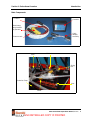
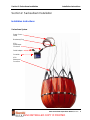
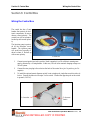
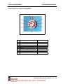
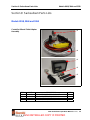
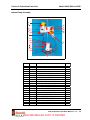
SEI Sacksafoam I is a helicopter dispensing system designed to enhance the efficiency of fire fighting operations. It features a sack that mounts in the Bambi bucket, eliminating spillage and corrosion. The system has an optional foam transfer pump for easy filling and a controller for precise foam injection. With its advanced features, SEI Sacksafoam I helps users protect lives and property from fires.
SEI Sacksafoam I is a helicopter dispensing system designed to enhance the efficiency of fire fighting operations. It features a sack that mounts in the Bambi bucket, eliminating spillage and corrosion. The system has an optional foam transfer pump for easy filling and a controller for precise foam injection. With its advanced features, SEI Sacksafoam I helps users protect lives and property from fires.


-
 1
1
-
 2
2
-
 3
3
-
 4
4
-
 5
5
-
 6
6
-
 7
7
-
 8
8
-
 9
9
-
 10
10
-
 11
11
-
 12
12
-
 13
13
-
 14
14
-
 15
15
-
 16
16
-
 17
17
-
 18
18
-
 19
19
-
 20
20
-
 21
21
-
 22
22
-
 23
23
-
 24
24
-
 25
25
-
 26
26
-
 27
27
-
 28
28
-
 29
29
-
 30
30
-
 31
31
-
 32
32
-
 33
33
-
 34
34
-
 35
35
-
 36
36
-
 37
37
-
 38
38


SEI Sacksafoam I is a helicopter dispensing system designed to enhance the efficiency of fire fighting operations. It features a sack that mounts in the Bambi bucket, eliminating spillage and corrosion. The system has an optional foam transfer pump for easy filling and a controller for precise foam injection. With its advanced features, SEI Sacksafoam I helps users protect lives and property from fires.
Ask a question and I''ll find the answer in the document
Finding information in a document is now easier with AI
Related papers
Other documents
-
Kmart 43127887 User manual
-
Crown Bolt 806536 User manual
-
Rexel 2100154 Datasheet
-
 UPCART MPB-1DX Installation guide
-
HQ W9-OHG-20BN Datasheet
-
-
 SEI Industries BAMBI MAX User manual
-
 T & S Brass & Bronze Works BL-5550-26 Datasheet
-
 Baldor-Reliance Reducer Oil Conversion Mobil SHC634 to Kluber UH1-6-460 Owner's manual
-
Romac Industries 243-1110 Installation guide


