Ariston RHB8IX Installation guide
- Category
- Hobs
- Type
- Installation guide
This manual is also suitable for

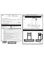
INSTALLATION INSTRUCTION
PRODUCT DIMENSIONS
CANOPY RANGEHOOD
RHB9IX
RHB8IX
PLEASE READ THE ENTIRE INSTRUCTION BEFORE INSTALLING THE CANOPY
All Dimensions are in mm
CONTROL
PANEL
a) Switch off the power to rangehood.
b) Use a small bladed screwdriver to prise off the light cover.
c) Use a cloth to remove the bulb. Do not touch the bulb with
fingers.
d) Replace with a new bulb using a cloth. Do not touch the bulb
with fingers. “Snap” the cover back in place.
e) Halogen bulb 12Volt/20Watt required.
For other accessories, parts or service, please contact your local supplier
(Refer to the Warranty Certificate).
BULB
LIGHT REPLACEMENT
For other Accessories, Parts or Service, please contact your local supplier or approved service agent
DUCTED
UNIDUCT FLEXI DUCT KIT is
recommended.
1569 Flexi Duct Kit (150mm)
INSTALLATION OPTION ACCESSORIES
RECIRCULATED
Use Manufacturer Product code:
1744 Recirculation Kit
WARNINGS
Care should be taken when removing filters in order to prevent the filter
This appliance is not intended for use by young children or infirm persons without
Young children should be supervised to ensure that they do not play with the
Upon installation the appliance must be positioned so that the plug is
There should be adequate ventilation of the room when the rangehood is used at
You must read the details concerning the method and frequency of cleaning.
There is a fire risk if cleaning is not carried out in accordance with the instructions.
Exhaust air must not be discharged into an existing flue used for exhausting
The recomended minimum distance between the hob surface and the lowest part
Attention should be given to ensure that any applicable regulations concerning
If the supply cord of this equipment is damaged, it must only be replaced by the
manufacturer or it’s service agent, or a similarly qualified person in order to
•
falling and causing damage to the hob top.
•
supervision.
•
appliance.
•
accessible.
•
the same time as appliances burning gas or other fuels.
•
•
• Do not flambé under the rangehood.
•
fumes from appliances burning gas or other fuels.
•
of the rangehood is 600mm. This should be increased to at least 650mm
if installed over a gas hob. We recommend 700mm.
•
the discharge of exhaust air is fulfilled.
•
avoid a hazard.
Electrical Rating:
385W (1.60A)
Max. at 230-240V 50Hz
RECOMMENDED UNIDUCT DUCTING
SYSTEMS FOR RANGEHOODS
318mm
900 / 800mm
72mm
500mm
277mm
528mm (min) to 728mm (max)
104803 issue B
ECN 04179
LEFT SLIDER=
LIGHTS OFF & ON
RIGHT SLIDER=
FAN OFF / LOW/ MED / HIGH SPEED
CONTROL LIGHT=
Arisit Pty Ltd
Australasian Distributor for Ariston Appliances
Ph: AUS (03) 9557 4044 - NZ (09) 306 10 20

PRE-INSTALLATION
Thank you for purchasing a quality stainless canopy rangehood.
We have a high standard of quality control and each rangehood is tested and
approved before it leaves the factory.
IMPORTANT : Please read prior to installation and operation.
•
Always switch the power off prior to installing, servicing or cleaning the appliance.
DUCTED
RECIRCULATED
Before drilling any holes check the wall and ceiling are clear of any electrical cables,
pipes etc. Fixing to a solid stud is recommended.
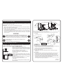
FRAMING
3
2
1
910mm
100
1 Fix the mounting washers in position, check with a spirit level across the washers to ensure
they are level.
6
104803 issue B
ECN 04179
CUT CORNICE
TO CLEAR COVER IF PREFERRED
160mm DIA HOLE
•
Never use the appliance without the filters.
•
Please read the notes on general cleaning, especially the filters.
•
Exhaust air must not be discharged into a heating flue or wall cavity, unless the
cavity is designed for that purpose.
•
Areas where the rangehood is installed that also have gas, oil or coal fired heaters,
must be well ventilated to prevent a partial vacuum in the room. This includes
gas hobs. (A partial vacuum in the room could result in too high a concentration
of gas in the air).
INSTALLING DUCTING
NOTE: All ducting must comply with local requirements and building codes.
2 Mark the position of the decorative chimney at ceiling and wall, cut the cornice moulding away
if required, to enable the chimney to fit flush against the wall and ceiling.
3 Mark and cut the hole in the ceiling to fit the ducting (160mm dia.)
This is position centrally above the canopy and 100mm from the wall
INSTALLING CEILING BRACKET
4 Using the screws supplied, fix the ceiling bracket to the wall, checking that it is aligned
with the hood.
FINAL ASSEMBLY
5 Remove protective plastic covering from all parts including the filters. Fit the canopy on the
mounting washers. Plug in power cord to the supply and check the function of the hood.
Fix the safety screw, connect and secure the ducting using the cable ties or duct date.
6 A rubber extrusion has been provided to hide any irregularities between the chimney and the
canopy / ceiling, to fit push over the top & bottom visible edges of the chimney. This edge
maybe shape so take care. If desired this extrusion may be omitted.
Assemble the telescope chimney to accurately suit the dimensions required and fix using the
screws supplied to the canopy and ceiling bracket
DUCTING: Ducting accessories are not supplied.
in the ceiling.
The air outlet from the motor requires
ducting which requires 160mm diameter hole
The unit is designed for 2400mm ceilings.
The chimney is telescopic and is designed for hood
installation between 600 to 800mm above the
cooking surface.
Read the instructions before starting the assembly.
Remove the filters to allow access to wall mounting holes.
NOTE: Stainless steel is very easily
damaged during installation if abraided or knocked by tools.
INSTALLATION OF UNIT
WARNING
All electrical work must be done in accordance with local and/or national electrical codes as
applicable. For safety, this product must be earthed. If you are unfamiliar with methods of
installing electrical wiring, employ the services of a qualified electrican.
Turn off power at service entrance before installing wiring or servicing this product.
The canopy is heavy, Please ensure adequate care when installing the canopy
to prevent personal injury.
The canopy must be installed onto a solid wall or solid studs.
lbs
lbs
IMPORTANT:
IF INSTALLING THE PRODUCT WITH A SPLASHBACK, THE SPLASHBACK MUST
BE INSTALLED FIRST. THE SPLASHBACK WILL DICTATE THE INSTALLATION
HEIGHT OF THE PRODUCT TO THE COOKING SURFACE.
IF SPLASHBACK IS USED,
THIS WILL DICTATE THE
INSTALLATION HEIGHT OF
PRODUCT
COOKING
SURFACE
914 mm
INSTALLATION
HEIGHT 700mm
CEILING
HEIGHT
2400mm
Ascertain the desired installation height of the canopy.
NOTE: Installation height ranges from 600 to 800mm
Optimum installation height is 700mm (650mm for gas)
above the hob.
This appliance must be positioned so that the electrical
plug is accessible.
CEILING
BRACKET
FIX SAFETY
SCREW AFTER
MOUNTING
CANOPY
KEYHOLES
IN REAR OF
CANOPY
(SHOWN
DOTTED)
4
5
5
FIX TO SOLID
IF SPLASHBACK IS USED,
THIS WILL DICTATE THE
INSTALLATION HEIGHT OF
PRODUCT
-
 1
1
-
 2
2


Ariston RHB8IX Installation guide
- Category
- Hobs
- Type
- Installation guide
- This manual is also suitable for
Ask a question and I''ll find the answer in the document
Finding information in a document is now easier with AI
Related papers
Other documents
-
ROBINHOOD RICT9SS Installation & Operating Manual
-
-
Schweigen PKCC-PARA3SE User manual
-
-
-
-
-
Euromaid INLC90 User manual
-
Euromaid INLC90 User manual
-