
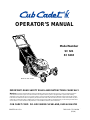
Model Number
SC 621
SC 621E
PRINTED IN U.S.A.
OPERATOR’S MANUAL
FORM NO.
770-10090A.fm
(12/99)
IMPORTANT: READ SAFETY RULES AND INSTRUCTIONS CAREFULLY
CUB CADET CORP. P.O. BOX 368023 CLEVELAND, OHIO 44136-9722
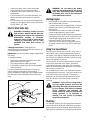
Warning: This unit is equipped with an internal combustion engine and should not be used on or near any unimproved forest-
covered, brush-covered or grass-covered land unless the engine’s exhaust system is equipped with a spark arrester meeting
applicable local or state laws (if any). If a spark arrester is used, it should be maintained in effective working order by the operator.
In the State of California the above is required by law (Section 4442 of the California Public Resources Code). Other states may have
similar laws. Federal laws apply on federal lands. A spark arrester for the muffler is available through your nearest engine authorized
service dealer or contact the service department, P.O. Box 368023 Cleveland, Ohio 44136-9722.
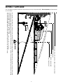
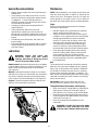
Model SC 621 Shown

2
TABLE OF CONTENTS
Content Page
Maintaining Safety.............................................................................................3
Slope Gauge......................................................................................................6
Assembling Your Lawn Mower...........................................................................7
Know Your Lawn Mower....................................................................................8
Operating Your Lawn Mower .............................................................................9
Making Adjustments ..........................................................................................11
Maintaining Your Lawn Mower...........................................................................13
Storing Your Lawn Mower..................................................................................16
Troubleshooting.................................................................................................17
Parts List............................................................................................................18
FINDING MODEL NUMBER
This Operator’s Manual is an important part of your new lawn mower. It will help you assemble, prepare and
maintain the unit for best performance. Please read and understand what it says.
Before you start assembling your new equipment, please locate the model plate on the
equipment and copy the information from it in the space provided below. The information on the
model plate is very important if you need help from our Customer Support Department or an
authorized dealer.
• You can locate the model number by looking down at the rear of the deck. A sample model plate is
explained below. For future reference, please copy the model number and the serial number of the
equipment in the space below.
CALLING CUSTOMER SUPPORT
If you have difficulty assembling this product or have any questions regarding the controls, operation or
maintenance of this unit, please call the Customer Dealer Referral Line.
Call 1- (800)-528-1009 to reach the Customer Dealer Referral Line. Please have your unit’s
model number and serial number ready when you call. See previous section to locate this
information. You will be asked to enter the serial number in order to process your call .
Copy the model number here:
Copy the serial number here:
(Model Number)
(Serial Number)
CUB CADET CORP.
CLEVELAND, OHIO 44136
P.O. BOX 368023

3
SECTION 1: MAINTAINING SAFETY
This Warning symbol points out important safety instructions which, if not followed, could endanger the
personal safety and/or property of yourself and others. Read and follow all instructions in this manual
before attempting to operate your lawn mower. Failure to comply with these instructions may result in
personal injury. When you see this symbol, heed its warning.
DANGER: Your lawn mower was built to be operated according to the rules for safe operation in
this manual. As with any type of power equipment, carelessness or error on the part of the operator can
result in serious injury. This lawn mower is capable of amputating hands and feet and throwing objects.
Failure to observe the following safety instructions could result in serious injury or death.
WARNING: The Engine Exhaust from this product contains chemicals known to the State of
California to cause cancer, birth defects or other reproductive harm.
GENERAL OPERATION
• Read this operator’s manual carefully in its entirety
before attempting to assemble this machine. Read,
understand, and follow all instructions on the machine
and in the manual(s) before operation. Be completely
familiar with the controls and the proper use of this
machine before operating it. Keep this manual in a
safe place for future and regular reference and for
ordering replacement parts.
• Your rotary mower is a precision piece of power
equipment, not a plaything. Therefore, exercise
extreme caution at all times. Your unit has been
designed to perform one job: to mow grass. Do not
use it for any other purpose.
• Never allow children under 14 years old to operate a
power mower. Children 14 years old and over should
only operate mower under close parental supervision.
Only responsible individuals who are familiar with
these rules of safe operation should be allowed to
use your mower.
• Keep the area of operation clear of all persons,
particularly small children and pets. Stop engine
when they are in the vicinity of your mower to help
prevent blade contact or thrown object injury.
Although the area of operation should be completely
cleared of foreign objects, an object may have been
overlooked and could be accidentally thrown by the
mower in any direction and cause serious personal
injury to the operator or any others allowed in the
area.
• Wear sturdy, rough-soled work shoes and close-fitting
slacks and shirts. Shirts and pants that cover the
arms and legs and steel-toed shoes are
recommended. Do not wear loose fitting clothes or
jewelry. They can be caught in moving parts. Never
operate a unit in bare feet, sandals, slippery or light
weight (e.g. canvas) shoes.
• Always wear safety glasses or safety goggles during
operation or while performing an adjustment or repair,
to protect eyes from foreign objects that may be
thrown from the machine in any direction.
• Thoroughly inspect the area where the equipment is
to be used. Remove all stones, sticks, wire, bones,
toys and other foreign objects which could be picked
up and thrown by the mower in any direction and
cause serious personal injury to the operator or any
others allowed in the area. Plan your mowing pattern
to avoid discharge of material toward roads,
sidewalks, bystanders and the like. To help avoid a
thrown objects injury, keep children, bystanders and
helpers at least 75 feet from the mower while it is in
operation.
• Do not put hands or feet near or under rotating parts.
Keep clear of discharge opening at all times as the
rotating blade can cause injury.
• Many injuries occur as a result of the mower being
pulled over the foot during a fall. Do not hang on to
the mower if you are falling; release the handle
immediately.
• Never pull the mower toward you while you are
walking. If you must back the mower away from a
wall or obstruction first look down and behind, and
then follow these steps:
• Step back from the mower to fully extend your
arms.
• Be sure you are well balanced with sure footing.
• Pull the mower back slowly, no more than half
way toward you.
• Repeat these steps as needed.
• Do not operate the mower while under the influence
of alcohol or drugs.
• Do not engage the self-propelled mechanism on units
so equipped while starting engine.
• The blade control handle is a safety device. Never
attempt to bypass its operation. Doing so makes the
safety device inoperative and may result in personal
injury through contact with the rotating blade. The
blade control handle must operate easily in both
directions and automatically return to the disengaged
position when released.

4
• Never operate the mower in wet grass. Always be
sure of your footing. A slip and fall can cause serious
personal injury. Keep a firm hold on the handle and
walk, never run. If you feel you are losing your
footing, RELEASE THE BLADE CONTROL HANDLE
IMMEDIATELY and the blade will stop rotating within
three seconds.
• Mow only in daylight or good artificial light.
• Stop the blade when crossing gravel drives, walks or
roads.
• If the equipment should start to vibrate abnormally,
stop the engine and check immediately for the cause.
Vibration is generally a warning of trouble.
• Shut the engine off and wait until the blade comes to
a complete stop before removing the grass catcher or
unclogging the chute. The cutting blade continues to
rotate for a few seconds after the engine is shut off.
Never place any part of the body in the blade area
until you are sure the blade has stopped rotating.
• Never operate mower without proper guards, grass
catcher, plates or other safety protective devices in
place.
• Muffler and engine become hot and can cause a
burn. Do not touch.
• Only use accessories approved for this machine by
the manufacturer. Read, understand, and follow all
instructions provided with the approved accessory.
• If situations occur which are not covered in this
manual, use care and good judgment. Contact your
dealer for assistance.
SLOPE OPERATION
For your safety, use the slope gauge included as part of this
manual to measure slopes before operating this unit on a
sloped or hilly area. If the slope is greater than 15 degrees
as shown on the slope gauge, do not operate this unit on
that area or serious injury could result.
DO:
• Mow across the face of slopes; never up and down.
Exercise extreme caution when changing direction on
slopes.
• Watch for holes, ruts, hidden objects, or bumps. Tall
grass can hide obstacles.
• Always be sure of your footing. A slip and fall can
cause serious personal injury. If you feel you are
losing your balance release the blade control handle
immediately and the blade will stop in less than 3
seconds.
DO NOT:
• Do not mow near drop-offs, ditches or embankments.
The operator could lose footing or balance.
• Do not mow slopes greater than 15 degrees as
shown on the slope gauge.
• Do not mow on wet grass. Reduced footing could
cause slipping.
CHILDREN
Tragic accidents can occur if the operator is not alert to the
presence of children. Children are often attracted to the
mower and the mowing activity. Never assume that children
will remain where you last saw them.
• Keep children out of the mowing area and under the
watchful care of a responsible adult other than the
operator.
• Be alert and turn mower off if a child enters the area.
• Before and while moving backwards, look behind and
down for small children or other objects.
• Never allow children under age 14 to operate the
mower. Children 14 years of age and above should
read and understand the operation instructions and
safety rules in this manual.
• Use extreme care when approaching blind corners,
shrubs, trees, or other objects that may obscure your
vision of a child or hazard.
SERVICE
• Use extreme care in handling gasoline and other
fuels. They are extremely flammable and the vapors
are explosive.
• Use only an approved gasoline container.
• Never remove gas cap or add fuel while the engine is
running. Allow engine to cool at least two minutes
before refueling.
• Replace gasoline cap securely and wipe off any
spilled gasoline before starting the engine as it may
cause a fire or explosion.
• Extinguish all cigarettes, cigars, pipes and other
sources of ignition.
• Never refuel machine indoors because flammable
vapors will accumulate in the area.
• Never store the machine or fuel container inside
where there is an open flame or spark such as a gas
water heater, space heater, or furnace.
• Never run an engine inside a closed area.
• To reduce fire hazard, keep mower free of grass,
leaves, or other debris build-up. Clean up oil or fuel
spillage. Allow mower to cool at least 5 minutes
before storing.
• Before cleaning, repairing, or inspecting, make
certain the blade and all moving parts have stopped.
Disconnect the spark plug wire, and keep the wire
away from the spark plug to prevent accidental
starting.
• Check the blade and engine mounting bolts at
frequent intervals for proper tightness. Also, visually
inspect blade for damage (e.g., bent, cracked or
worn). Replace with blade which meets original
equipment specifications listed in this manual.
• Keep all nuts, bolts, and screws tight to be sure the
equipment is in safe working condition.
• Never tamper with safety devices. Check their proper
operation regularly.

5
• After striking a foreign object, stop the engine,
remove the wire from the spark plug, and thoroughly
inspect the mower for any damage. Repair the
damage before starting and operating the mower.
• Never attempt to make a wheel or cutting height
adjustment while the engine is running.
• Grass catcher components are subject to wear,
damage and deterioration, which could expose
moving parts or allow objects to be thrown. For safety
protection, frequently check components and replace
with manufacturer’s recommended parts, when
necessary.
• Mower blades are sharp and can cut. Wrap the
blade(s) or wear gloves, and use extra caution when
servicing them.
• Do not change the engine governor setting or
overspeed the engine. Excessive engine speeds are
dangerous.
WARNING - YOUR RESPONSIBILITY: Restrict the use of this power machine to persons who read,
understand and follow the warnings and instructions in this manual and on the machine.
NOTE: Not all safety labels shown may apply to your lawn mower.

6
SECTION 2: SLOPE GAUGE
Use this page as a guide to determine slopes where you may not operate safely. Do not operate your lawn mower
on such slopes.
15°
SIGHT AND HOLD THIS LEVEL WITH A VERTICAL TREE
A POWER POLE
A CORNER OF A BUILDING
OR A FENCE POST
F
O
L
D
O
N
D
O
T
T
E
D
L
I
N
E
,
R
E
P
R
E
S
E
N
T
I
N
G
A
1
5
°
S
L
O
P
E
WARNING
Do not mow on inclines with a slope in excess of 15 degrees (a rise of approximately 2-1/2 feet every 10 feet). A riding mower could
overturn and cause serious injury. If operating a walk-behind mower on such a slope, it is extremely difficult to maintain your footing
and you could slip, resulting in serious injury.
Operate RIDING mowers up and down slopes, never across the face of slopes.
Operate WALK-BEHIND mowers across the face of slopes, never up and down slopes.

7
SECTION 3: ASSEMBLING YOUR LAWN MOWER
IMPORTANT:
This unit is shipped without gasoline or oil
in the engine. Be certain to service engine with gasoline
and oil as instructed in the separate engine manual
before operating your mower.
NOTE: Reference to right or left hand side of the mower
is observed from the operating position.
Removing Unit From Carton
• Remove staples, break glue on top flaps, or cut
tape at carton end and peel along top flap to open
carton.
• Remove loose parts if included with unit (i.e.,
operator’s manual, oil, etc.)
• Cut along corners, lay carton down flat, and remove
packing material.
• Roll or slide unit out of carton and check carton
thoroughly for loose parts.
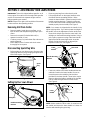
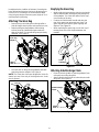
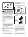
Disconnecting Spark Plug Wire
• Before setting up your lawn mower, disconnect the
spark plug wire from the spark plug and ground to a
bolt on the engine. See Figure 1.
Figure 1
Setting Up Your Lawn Mower
Figure 2
• Remove grass bag from unit and set it aside.
• Lift up and pull back on the upper handle to raise
the handle into the operating position. Make
certain the lower handle is seated securely into the
handle mounting brackets. Tighten the wing nuts
on each side of the handle (carriage bolts must be
seated properly into the handle) See Figure 2.
NOTE: Your mower is shipped with the handle in the
higher height position. If you wish to lower the height of
the handle, refer to the Adjustment Section at this time.
• Remove the hairpin clips from the outer hole in the
weld pins on the handle mounting brackets. Using a
pair of pliers, squeeze one leg of the lower handle
against the handle mounting bracket. Insert the
hairpin clip into the inner hole on the weld pin.
Repeat on other side. See Figure 3.
Figure 3
• Fasten the cables to the lower handle with the two
cable ties found on the lower handle. Be sure to
insert the post on the cable ties into the holes
provided on the lower handle. These holes may be
found on either the inside or outside of the handles.
Pull the cable ties tight and trim off the excess.
See Figure 4.
Figure 4
NOTE: Make certain the drive cable is routed around
the outside and above the lower handle so it does not
interfere with attaching the grass bag.
Spark
Plug
Spark Plug
Wire
Handle Assembly
Handle Mounting
Bracket
Wing Nut
Handle Mounting
Bracket
Lower
Handle
Hairpin
Clip
Inner Hole
Cable Tie
Lower
Handle

8
Figure 5
• The rope guide, which is connected to the support
rod, is located on the right side of lower handle.
See Figure 5.
• With the spark plug wire disconnected and
grounded, hold the blade control handle against the
upper handle, and pull the starter rope out of the
engine. Release the blade control handle. Slip the
starter rope into the rope guide.
SECTION 4: KNOW YOUR LAWN MOWER
Read this operator’s manual and safety rules before operating your lawn mower. Compare the illustrations in Figure
6 with your lawn mower to familiarize yourself with the location of various controls and adjustments. Save this
manual for future reference.
WARNING: The operation of any lawn mower can result in foreign objects being thrown into the
operator’s eyes and causing severe eye damage. Always wear safety glasses while operating the
mower, or while performing any adjustments or repairs on it.
Figure 6
Recoil Starter
The recoil starter is attached to the right lower handle.
Stand behind the unit and pull the recoil starter to start
the unit. See Figure 6.
Blade Control Handle
The blade control handle is located on the upper handle
of the mower. The blade control handle must be
depressed in order to operate the unit. Release blade
control handle to stop engine and blade. See Figure 6.
WARNING: This blade control mechanism
is a safety device. Never attempt to bypass
its operations.
Rear Cutting Height Adjustment Lever
The rear wheel cutting height adjustment lever is
located above the left rear wheel. The front wheel
cutting height is determine by the location of each
caster wheel. See Figure 6.
Drive Clutch Control
The drive clutch control is located on the upper handle.
Squeeze the drive control to engage the drive system.
Release the clutch control to disengage the drive
system. Release the clutch control to slow down when
approaching an obstacle, making a turn, or stopping.
See Figure 6.
Shift Lever
The shift lever is located on the drive clutch control
housing on the upper handle. This lever is used to
select the forward speed of the mower. When changing
speed selection, release the drive clutch control. See
Figure 6.
NOTE: Move the shift lever only when the engine is
running. Changing the shift lever setting with the engine
off can cause damage to the mower.
Starter
Rope
Rope
Guide
Lower
Handle
Support
Rod
Blade Control
Handle
Recoil
Starter
Rear Cutting Height
Adjustment Lever
Drive Clutch
Control
Shift
Lever
Front Wheel
Height Adjuster
Front Wheel
Caster Locks

9
Front Wheel Caster Locks
The caster locks are located on top of each caster
wheel. Refer to the Adjustment Section.
Engine Controls
See the separate engine manual for the location and
function of the controls on the engine.
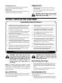
Stopping Engine
• Release blade control handle to stop the engine
and the blade.
• Disconnect spark plug wire and ground it to the
post on the engine.
WARNING: Before using your lawn mower,
again refer to the Safety Section in this
manual. Always be careful.
SECTION 5: OPERATING YOUR LAWN MOWER
WARNING: Keep hands and feet away
from chute area on the cutting deck. The
operation of any lawn mower can result in
foreign objects being thrown into the
eyes, which can result in severe eye
damage. Always wear safety glasses or
eye shields.
NOTE: For shipping purposes your mower is set with
the wheels in a low cutting height position. For best
results raise the cutting position until it is determine
which height is best for your lawn. See the adjustment
section for details.
Gas and Oil Fill-Up
Service the engine with gasoline and oil as instructed in
the separate engine manual packed with your mower.
Read instructions carefully.
WARNING: Never fill fuel tank indoors with
engine running or until the engine has
been allowed to cool for at least two
minutes after running.
Before Starting Your Mower
• Attach spark plug wire to spark plug. Make certain
the metal cap on the end of the spark plug wire is
fastened securely over the metal tip on the spark
plug.
• Check for proper drive clutch operation using the
NEUTRAL ADJUSTMENT TEST.
Neutral Adjustment Test
To perform the neutral adjustment test answer the
following questions.
• With the drive clutch control released, push mower
forward and pull it backward. Does it move freely?
Towards Better Mower Performance
1. Read this manual in its entirety before you start
the lawn mower. Instructions given here have
been designed for maintaining safety while
getting the best performance from your mower.
Follow the instructions closely.
2. Pour fresh, clean gasoline into the mower’s gas
tank until the tank is full. Do not use gasoline
that is more than 30 days old.
3. Always use a fuel stabilizer. It will double the life
of the gasoline used.
4. Make sure to connect the mower’s spark plug
wire before trying to start the engine.
5. Add engine oil to the oil fill on the mower engine.
Check the dipstick and add more if necessary.
Remember that the oil level has to touch the fill
line.
6. Locate the primer decal near the primer bulb on
the engine, and read its instruction. Using your
thumb, press the primer bulb slowly as many
times as the decal advises.
7. Hold control handle down and pull rope firmly to
start the engine.
8. Set cutting height adjustment lever to middle
setting and mow a single pass on your lawn;
then adjust to desired height for a closer cut.
9. When bagging the grass clippings, remove
mulch plug/cover and store.
10. When mulching, remove the grass bag and
store. Insert the mulch plug/cover on the mower.
11. In heavy growing season, it may be necessary
to mow lawn twice weekly. Clumps of grass
clippings left behind on the lawn usually means
that the grass is too high to mulch.
12. Before storing the lawn mower for the winter,
use stabilizer-treated fuel and run the tank dry.
13. Thirty days before start of the new season,
check the air filter, spark plug and blade on the
lawn mower, and replace if needed.
For more details about proper lawn care, visit our website at www.CubCadet.com

10
• Squeeze the drive clutch control and pull the
mower backward. Do the rear wheels lock?
• Is the drive clutch control cable free of kinks or
sharp bends?
• If you answered “yes” to all three questions, your
mower passed the test and you can start your
mower.
• If you answered “no” to any of the three questions,
you will have to adjust the drive clutch control in the
ADJUSTMENT SECTION.
Electric Start Units Only
WARNING: The battery contains corrosive
fluid and toxic material. Handle with care.
Keep away from children. Do not puncture
disassemble, mutilate or incinerate.
Explosive gasses could be vented during
charging or discharging. Use in a well-
ventilated area away from sources of
ignition.
Charging Instructions: Charge battery for
approximately 16 hours before initial use; however, do
not charge longer than 20 hours.
IMPORTANT:
Use only the battery charger supplied with
this mower.
To charge the battery:
• Remove the protective cap from the end of the
battery pack lead. See Figure 7.
• Plug charger lead into battery pack lead.
• Insert battery charger plug into 120 volt standard
household outlet.
It is very important to follow this order of action for
proper charging of the battery. After charging,
disconnect battery charger plug from household outlet
first, then disconnect charger lead from battery pack
lead.
Figure 7
WARNING: Do not remove the battery
pack from the handle panel for any reason
other than replacement. When replacing
the battery pack, refer to the instructions
in the maintenance section.
Starting Engine
• Prime engine as instructed in the separate engine
manual packed with your unit.
• Your lawn mower may be equipped with a constant
speed throttle, which is set at full throttle for best
performance.
• Stand behind the mower and squeeze the blade
control handle against the upper handle.
• Grasp recoil starter handle and pull rope out slowly
until engine reaches the start of compression cycle
(rope will pull slightly harder at this point). Let the
rope rewind slowly. Pull rope with a rapid,
continuous, full arm stroke. Keeping a firm grip on
the starter handle, let the rope return to the starter
slowly.
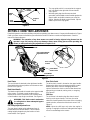
Using Your Lawn Mower
Be sure that the lawn is clear of stones, sticks, wire, or
other objects which could damage the lawn mower or
the engine. Such objects could be accidently thrown by
the mower in any direction and cause serious personal
injury to the operator and others.
For best results, do not cut wet grass because it tends
to stick to the underside of the mower, preventing
proper discharge of grass clippings, and could cause
you to slip and fall. New grass, thick grass, or wet grass
may require a narrower cut.
For a healthier lawn, never cut off more than one-third
of the total length of the grass. Your lawn should be cut
in the fall as long as there is growth. This mower is
designed to be operated at full throttle to give you the
best cut and do the most effective job of mowing or
mulching.
WARNING: If you strike a foreign object,
stop the engine. Remove wire from the
spark plug, thoroughly inspect the mower
for any damage, and repair the damage
before restarting and operating the
mower. Extensive vibration of the mower
during operation is an indication of
damage. The unit should be promptly
inspected and repaired.
Mulching
For effective mulching, do not cut wet grass because it
tends to stick to the underside of the deck, preventing
proper mulching of grass clippings. New or thick grass
may require a narrower cut. The ground speed should
Cap
Charger
Lead
Charger
Plug
Battery
Pack

11
be adjusted to the condition of the lawn. If mowing has
been delayed and the grass has been allowed to grow
in excess of 4”, mulching is not recommended. Mow
using the grass bag to reduce the grass height to 3 1/4”
maximum before mulching.
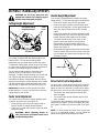
Attaching The Grass Bag
• Remove wing nuts holding the mulching baffle or
side discharge chute in place and remove from unit.
• Replace with grass bag adapter, while making
sure the inner lip of attachment goes under the
edge of the deck. Secure with wing nuts previously
removed. See Figure 8.
Figure 8
• Lift chute door on the grass bag adapter and slide
grass bag onto the adapter. See Figure 9.
NOTE: The chute door has been designed to move the
starter rope out of the way of the bag when the chute
door is opened.
Figure 9
Emptying the Grass Bag
• While holding the grass bag by both the rear handle
and the lower handle, lift the grass bag straight up
off the adapter. The chute door will move the rope
out of the way of the bag.
• Continue to hold the lower handle and raise the
rear of the grass bag up toward your chest. The
grass bag will open and the grass clippings will
disperse. See Figure 10.
• When replacing the grass bag, be sure the top of
the bag rests on the wire support between the
handles.
Figure 10
Attaching Side Discharge Chute
• Remove mulching baffle or grass bag adapter from
unit by disconnecting wing nuts.
• Attach side discharge chute to unit and secure with
wing nuts. See Figure 11.
Figure 11
Grass Bag
Adapter
Wing
Nuts
Grass
Bag
Chute
Door
Grass
Clippings
Side Discharge
Chute
Wing
Nuts

12
SECTION 6: MAKING ADJUSTMENTS
WARNING: Do not at any time make any
adjustments without first stopping engine
and disconnecting spark plug wire.
Cutting Height Adjustment
Figure 12
Your mower is shipped with the cutting height in the
lowest position. The rear wheel cutting height
adjustment lever is located above the left rear wheel.
To adjust the cutting height, pull the lever out and away
from the mower and then move it forward or backward
to select a new cutting height. See Figure 12.
The front wheel cutting height is determine by the
selection of one of six positions in each caster
assembly. To adjust, remove the wing nut from the axle
bolt. Slide the axle bolt and spring washer from the
assembly and select a cutting height. With the spring
washer on the axle bolt, reinsert hardware in the square
hole desired through the wheel assembly and secure
with the wing nut previously removed. See Figure 12.
IMPORTANT:
All wheels must be placed in the same
relative position. For rough or uneven lawns, raise the
cutting height of your mower.
Caster Lock Adjustment
The casters can be locked in a straight ahead position
or position to swivel freely. See Figure 12.
• Lift and place the lock pins in the larger holes to
lock the wheels for straight ahead operation.
• Place pins in smaller holes to allow casters to rotate
freely for turning.
WARNING: When operating mower on
hills, front wheels should be locked in the
straight ahead position.
Handle Height Adjustment
Your mower is shipped with the handle in the higher
height position. To lower the height proceed as follows:
• Remove the starter rope from the rope guide.
• Remove the upper handle by removing the hand
knobs and carriage bolts. Lay the upper handle out
of the way, being careful not to bend or kink the
cables.
• Remove the hairpin clips from the weld pins on the
handle brackets. Press out on the legs of the lower
handle. Remove lower handle from the mower.
• Turn lower handle around so the notch on the
bottom of the lower handle is facing forward.
Reassemble, placing the bottom holes in the
handle over the weld pins in the handle mounting
bracket.See Figure 13.
• Reassemble the upper handle to the lower handle.
• Place the hairpin clips in the inner holes in the weld
pins and attach the starter rope as instructed in the
Assembly Section.
Figure 13
Drive Clutch Control Adjustment
The drive clutch control adjustment wheel is located in
the drive clutch control handle housing and is used to
tighten or loosen the drive belt. You will have to adjust
the drive clutch control if any of the following happens:
• The mower does not propel itself with the drive
clutch engaged.
• The mower’s drive wheels hesitate with the drive
clutch engaged.
To resolve the above problems, rotate the adjustment
wheel with your fingers. Clockwise to tighten the cable
and counter-clockwise to loosen the cable. See Figure
14.
NOTE: For some people the drive clutch control may
not be in a comfortable position. You can adjust the
handle out by tightening the adjustment wheel.
Rear Wheel Cutting
Height Adjustment
Axle Bolt
Caster
Locks
Notch
Lower Handle

13
Figure 14
Shift Lever Cable Adjustment
Periodic adjustment of the six speed shift cable may be
required due to normal wear on the cable. Adjustment
is needed if all six speeds do not work.
The adjustable cable bracket is located on the left side
of the mower beside the engine.
• Start engine and place speed control lever in the
sixth speed position. See Figure 15.
• Stop engine and disconnect spark plug wire and
ground it against engine.
• Loosen hex nut which secures the adjustable cable
bracket. See Figure 15.
• Push back on the adjustable cable bracket and
tighten hex nut.
Figure 15
Engine Adjustments
See the separate engine manual packed with your unit
for adjustments to the engine.
SECTION 7: MAINTAINING YOUR LAWN MOWER
Adjustment
Bottom View
Wheel
Drive Clutch
Control
Upper
Handle
Bottom View
Speed Control
Lever
Upper
Handle
Hex Nut
Adjustable Cable
PUSH
Bracket
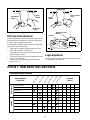
Customer Responsibilities
MAINTENANCE
SCHEDULE
P
R
O
D
U
C
T
E
N
G
I
N
E
SERVICE
DATES
A
fte
r
e
a
c
h
u
s
e
E
v
e
r
y
2
5
h
o
u
r
s
E
v
e
r
y
5
0
h
o
u
r
s
B
e
f
o
r
e
s
t
o
r
a
g
e
E
v
e
r
y
1
0
0
h
o
u
r
s
O
n
c
e
a
s
e
a
s
o
n
Lubricate wheels
Clean deck
Blade care
Change oil
Clean engine
Replace air filter
Check spark plug
Check spark arrester (if any)
Lubricate blade control

14
General Recommendations
• Always observe safety rules when performing any
maintenance.
• The warranty on this lawn mower does not cover
items that have been subjected to operator abuse
or negligence. To receive full value from the
warranty, operator must maintain the lawn mower
as instructed in this manual.
• Changing of engine governed speed will void
engine warranty.
• Some adjustments will have to be made
periodically to maintain your unit properly. All
adjustments in the Making Adjustments section of
this manual should be checked at least once each
season.
• Periodically check all fasteners and make sure
these are tight.
• Follow the maintenance schedule under Customer
Responsibilities to get quality performance from
your lawn mower.
Lubrication
WARNING: Always stop engine and
disconnect spark plug wire before
cleaning, lubricating or doing any kind of
service work on the lawn mower.
Blade Control: Lubricate the pivot points on the blade
control handle at least once a season with light oil. The
blade control must operate freely in both directions.
See Figure 16.
Wheels: Lubricate the wheels at least once a season
with light oil (or motor oil). If the wheels are removed for
any reason, lubricate the surface of the axle bolt and
inner surface of the wheel with light oil. See Figure 16.
Engine: Follow the separate engine manual packed
with you unit for lubrication instructions.
Figure 16
Maintenance
NOTE: When tipping the unit, empty the fuel tank and
keep the spark plug side of engine up. Never tip the
mower more than 90 degrees and do not leave the
mower tipped for any length of time. Oil can drain into
the upper part of the engine causing a starting problem.
Engine
Refer to the separate engine manual for all engine
maintenance instructions.
• Maintain engine oil as instructed in the separate
engine manual packed with your unit.
• Service air cleaner every 25 hours under normal
conditions. Poor engine performance and flooding
usually indicate that the air cleaner should be
serviced. To service the air cleaner, refer to the
separate engine manual packed with your unit.
• The spark plug should be cleaned and the gap
reset once a season. Spark plug replacement is
recommended at the start of each mowing season.
• Clean the engine regularly with a cloth or brush.
Keep the cooling system (blower housing area)
clean to permit proper air circulation which is
essential to engine performance and life. Be certain
to remove all grass, dirt, and combustible debris
from muffler area.
Deck
The underside of the mower deck should be cleaned
after each use to prevent a buildup of grass clippings,
leaves, dirt, or other matter. If this debris is allowed to
accumulate, it will invite rust and corrosion, and may
prevent proper mulching, discharge, or bagging. The
deck may be cleaned by tilting the mower and scraping
clean with a suitable tool (make certain the spark plug
wire is disconnected).
IMPORTANT:
We do not recommend the use of a
pressure washer or garden hose to clean your unit.
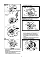
Cutting Blade Removal, Replacement, and Sharpening
• When removing the cutting blade for sharpening or
replacement, protect your hands with a pair of
heavy gloves or use a heavy rag to hold the blade.
• Remove the bolt and the blade bell support which
hold the blade and the blade adapter to the engine
crankshaft. See Figure 17.
• Remove the blade and the adapter from the
crankshaft.
WARNING: Periodically inspect the blade
adapter for cracks, especially if you strike
a foreign object. Replace when necessary.
Lubricate

15
Figure 17
WARNING: Periodically inspect the blade
adapter for cracks, especially if you strike
a foreign object. Replace when necessary.
When sharpening the blade, follow the original angle of
grind as a guide. It is extremely important that each
cutting edge receives an equal amount of grinding to
prevent an unbalanced blade. An unbalanced blade will
cause excessive vibration when rotating at high
speeds. It may cause damage to the mower, and could
break causing personal injury.
The blade can be tested by balancing it on a round
shaft screwdriver. Remove metal from the heavy side
until it balances evenly. It is recommended that the
blade always be removed from the adapter when
testing for balance. Before installing the blade and the
blade adapter to the unit, lubricate the engine
crankshaft and the inner surface of the blade adapter
with light oil.
• Be sure to install the blade with the side of the
blade marked “Bottom” (or with part number) facing
the ground when the mower is in the operating
position.
• Slide the blade adapter onto the engine crankshaft.
• Place the blade on the adapter. Be certain the
blade is aligned and seated on the blade adapter
flanges.
• Place blade bell support on blade. Make sure the
notches on the blade bell support are aligned with
small holes in the blade.
• Replace hex bolt and tighten hex bolt to torque: 450
in. lbs. min., 600 in. lbs. max.
NOTE: To ensure safe operation of your mower, the
blade bolt must be checked periodically for correct
torque.
Drive Belt Removal and Replacement
• Disconnect the spark plug wire and ground it
against the engine.
• Drain the fuel tank or place a piece of plastic
beneath the cap to prevent gasoline leakage.
• Place shift lever in the first position and tip the
mower on its side.
• Remove the center bolt which secures the blade to
the crankshaft followed by blade bell support,
blade, and blade adapter.
• Move the cutting height adjustment to the highest
position.
• Remove the three hex screws holding the baffle to
the deck and pivot baffle towards the rear of the
mower. See Figure 18.
Figure 18
• Remove the hex bolt from the rear of unit holding
the transmission to the mower housing.
See Figure 19.
Figure 19
• Tilt the transmission forward and loosen the idler
pulley bolt and lock nut half a turn. See Figure 20.
• Using a pair of pliers, pull back and rotate belt
keeper bracket from the slot on the idler pulley.
• Slide the belt out from between the belt keeper
bracket and the idler pulley.
• Squeeze the belt together and push it forward,
while pressing the control arm inward towards the
deck and remove the six speed cable from the slot.
See Figure 20.
• Pivot the control arm down away from the pulley
and belt.
• Lift off the lower pulley assembly and remove the
old belt from around the crankshaft. See Figure 20.
• Place the new belt over the transmission pulley.
Start the belt in the pulley groove and rotate the
pulley until the belt is seated in the transmission
pulley.
Blade
Hex Bolt
Blade Bell
Adapter
Support
Baffle
Cutting Height
Adjustment
Hex Bolt

16
Figure 20
• Place the belt between the idler pulley and the belt
keeper bracket.
• Using pliers, rotate the belt keeper bracket so that it
snaps into slot on the idler bracket.
• Tighten the idler pulley bolt and lock nut half a turn.
• Place the belt between the two pulley halves on the
crankshaft. Make sure to route the belt inside the
belt guard pin. See Figure 21.
Figure 21
IMPORTANT:
When replacing the belt, do not disas-
semble the lower pulley assembly.
Figure 22
• Pinch both sides of the belt together so that the belt
is not in the pulley groove, and the lower pulley can
be pushed towards the engine. See Figure 22.
• Pivot the control arm back to its original position
and reinstall the six-speed cable into the slot. See
Figure 23.
• Check and make sure the belt is routed inside the
pulley halves and the belt guard pin.
Figure 23
• Reinstall the bolt securing transmission to rear
mower housing.
Transmission
Belt Keeper
Bracket
Idler Pulley
Belt
Idler Pulley
Bracket
Transmission
Pulley
Bolt and
Locknut
Belt
Six-Speed
Control
Cable Slot
Arm
Belt
Lower
Crankshaft
Pulley Half
Belt
Lower
Pulley
Half
Upper
Pulley
Half
Belt
Tab
Guard Pin
Belt
Lower Pulley
Belt
Guard Pin
Half
Six-Speed
Cable Slot
Control
Arm

17
• Pivot the baffle back to its original position and
secure with three hex screws earlier removed.
• Lightly lubricate the inside of the blade adapter and
reinstall the spacer, wave washer, blade adapter
assembly, and blade in the correct order.
• Tighten the hex bolt to secure the blade to torque:
450-600 in. lbs.
SECTION 8: STORING YOUR LAWN MOWER
The following steps should be taken to prepare your
lawn mower for storage.
• Clean and lubricate mower thoroughly as described
in the lubrication instructions.
IMPORTANT:
We do not recommend the use of a
pressure washer or garden hose to clean your unit.
• Refer to engine manual for correct engine storage
instructions.
• Coat mower’s cutting blade with chassis grease to
prevent rusting.
• Store mower in a dry, clean area. Do not store next
to corrosive materials, such as fertilizer.
NOTE: When storing any type of power equipment in a
poorly ventilated or metal storage shed, care should be
taken to rust-proof the equipment. Using a light oil or
silicone, coat the equipment, especially cables and all
moving parts.
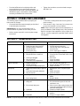
SECTION 9: TROUBLESHOOTING
NOTE: For repairs beyond the minor adjustments listed above, contact your nearest authorized service dealer.
Problem Cause Remedy
Engine fails to start 1. Blade control handle disengaged.
2. Spark plug wire disconnected.
3. Fuel tank empty or stale fuel.
4. Blocked fuel line.
5. Faulty spark plug.
1. Engage blade control handle.
2. Connect wire to spark plug.
3. Fill tank with clean, fresh gasoline.
4. Clean fuel line.
5. Clean, adjust gap, or replace.
Engine runs erratic 1. Spark plug wire loose.
2. Blocked fuel line or stale fuel.
3. Vent in gas plugged.
4. Dirty air cleaner.
5. Carburetor out of adjustment.
1. Connect and tighten spark plug wire.
2. Clean fuel line; fill tank with clean, fresh
gasoline
3. Clear vent.
4. Clean air cleaner.
5. Adjust carburetor.
Engine overheats 1. Engine oil level low.
2. Air flow restricted.
3. Carburetor not adjusted properly.
1. Fill crankcase with proper oil.
2. Remove blower housing and clean.
3. Adjust carburetor.
Idles poorly 1. Spark plug fouled, faulty or gap too
wide.
2. Carburetor improperly adjusted.
3. Dirty air cleaner.
1. Reset gap to .030” or replace spark
plug.
2. Adjust carburetor.
3. Clean air cleaner.
Excessive vibration 1. Cutting blade loose or unbalanced.
2. Bent cutting blade.
1. Tighten blade and adapter. Balance
blade.
2. Replace blade.
Mower will not mulch grass 1. Engine speed too low.
2. Wet grass.
3. Excessively high grass.
4. Dull blade.
1. Set throttle at full throttle.
2. Do not mow when grass is wet; wait
until later to cut.
3. Mow once at a high cutting height, then
mow again at desired height or make a
narrower cutting path.
4. Sharpen or replace blade.
Uneven cut 1. Wheels not positioned correctly.
2. Dull blade.
1. Place all four wheels in same height
position.
2. Sharpen or replace blade.

18
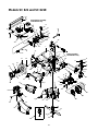
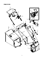
Models SC 621 and SC 621E
Transmission Assembly
for Reference only
Pulley Assembly
for Reference only
41
40
65
36
24
17
21
19
34
18
13
28
26
32
29
11
20
26
28
35
12
14
15
30
33
26
31
25
16
27
23
22
64
38
7
66
2
2
37
39
60
51
58
55
59
61
56
16
25
31
4
5
73
4
5
74
87
85
86
84
83
82
9
9
8
10
8
68
68
67
69
70
48
49
48
81
78
79
76
54
53
46
47
50
44
45
52
77
80
43
80
77
75
6
1
3
6
2
88

19
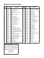
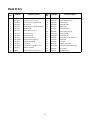
Models SC 621 and SC 621E
Ref.
No.
Part No. Description
Ref.
No.
Part No. Description
1. 710-0134 Carriage Screw 1/4-20 x .62 44. 682-9024 Caster Bracket Assembly: RH
2. 710-0654A Screw TT:3/8-18:1.00 45. 682-9026 Caster Bracket Assembly: LH
3. 710-0703 Carriage Screw 1/4-20 x .750 46. 711-1146 Caster Axle .374 Dia x 2.50”
4. 712-0397 Wing Nut 1/4-20 47. 736-0232 Wave Washer
5. 723-0233 Push Nut .25 I.D. x .50 O.D. 48. 731-1888 Hub Cap w/ hole
6. 736-0204 Flat Washer .334 I.D.x .62 x.03 49. 734-1857 Wheel 7 x 2 Link
7. 782-0046A Deck - 21” 50. 712-0397 Wing Nut 1/4-20
8. 710-0653 Screw TT. 1/4-20 x .375 51. 734-1981 Wheel 9 x 2 Link
9. 710-1220 Screw HL. 1/2-14 x .750 52. 712-3004A Lock Nut 5/15-18
10. 731-1828 Baffle 53. 714-0104 Cotter Pin .072 x .12 Lg.
11. 638-0012 Rear Axle Assembly 54. 736-0264 Flat Washer .330 x .830 x .060
12. 782-0566A Pivot Arm Assembly 55. 10622B Plastic Spring Ratchet
13. 682-7526 Transmission Axle Assembly 56. 748-0381 Pawl - R.H.
14. 682-7528 Chain Cover Assembly 57. 748-0188B Pawl - L.H. (Not Shown)
15. 710-0653 Screw TT 1/4-20 x .375 58. 16855 Ratchet Pawl Plate
16. 710-0751 Cap Screw HH 1/4-20 x .620 59. 738-0137A Screw Shoulder .340 x .285
17. 710-1652 Screw AB 1/4--20x.625 60. 712-0414 Top Lock Tab Weld Nut 1/4-20
18. 710-1315 Screw 3/8 116 x .25 61. 731-0982A Hubcap, w/o hole
19. 711-0835 Clevis Pin .50 Dia. x 4.82 Lg. 63. 751B213146 Throttle Casing Clamp
20. 713-0453 Chain #48 .500P x 24L 64. 725-0157 Cable Tie
21. 714-0474 Cotter Pin .125O.D. x .75 65. 710-0604 Hex Screw 5/16-18
22. 720-0223 Grip 66. 754-0460 Belt, 3/8”x 39.24”
23. 732-0803A Spring Lever 67. 742-0741 21” Mulching Blade
24. 732-0832 Torsion Spring 68. 748-0377C Blade Adapter
25. 736-0270 Bell Washer .285 x .75 x .082 69. 736-0524A Blade Bell Support
26. 736-0369 Flat Washer .508 I.D. 1.000 x.020 70. 710-1257 Hex Bolt 3/8-24x2.5”Lg.
27. 738-0529 Shoulder Nut .825 Dia. x .165 Lg. 73. 731-1832 Side Discharge Chute
28. 741-0324 Hex Flange Bearing .506 I.D. x .590 L. 74. 731-1833 Mulch Cover
29. 741-0522 Hex Flange Bearing .506 I.D. x.715 L. 75. 726-0214 Push Cap
30. 741-0978 Hex. Sleeve Bearing .504 I.D. x .830 L. 76. 732-0306 Compression Spring
31. 748-0318 Wheel Rachet 77. 736-0366 Flat Washer .5/8 I.D. x 1” O.D.
32. 750-0151 Spacer .550 I.D. x /750 O.D. 78. 736-0931 Flat Washer .203 x .403 x .040
33. 750-0515 Spacer .51 .D. x .70 O.D. x 38 L. 79. 737-3000 Fitting - Grease
34. 750-0807 Spacer .385 x .624 x .700 80. 741-0685 Flange Bearing
35. 750-1056 Shoulder Spacer .385 I.D. x .715 Lg. 81. 747-0924 Locking Pin
36. 782-0568 Height Adjuster Spring Bracket 82. 631-0066 Chute Ass’y
37. 682-3052 Handle Bracket Ass’y. R.H. 83. 731-1713A Discharge Chute
38. 682-3053 Handle Bracket Ass’y. L.H. 84. 747-0965 Pivot Rod
39. 710-1348 Screw AB 1/4-14 x .500 85. 732-0819 Torsion Spring
40. 731-1901 Trail Shield 86. 726-0111 Push Cap
41. 732-0842 Trail Shield Wire 87. 731-1874 Chute Door
43. 682-9021A Caster Assembly L.H. 88. 710-0260 Carriage Bolt 5/16-18 x.62
682-9020A Caster Assembly R.H. (Not Shown)
NOTE: For painted parts, please refer to
the list of color codes below. Please add the
applicable color code, wherever needed, to
the part number to order a replacement part.
For instance, if a part, numbered 700-xxxx,
is painted Cub Yellow, the part number to
order would be 700-xxxx-0498.
Cub Yellow: 0498
Cub Beige: 0499
Powder Black: 0637

20
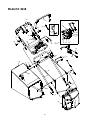
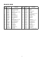
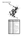
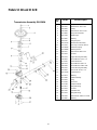
Model SC 621E
16
21
18
20
23
22
17
19
24
A
26
25
A
28
27
29
14
30
2
2
4
36
3
5
1
5
3
7
6
34
33
31
32
35
39
40
56
12
11
42
41
46
38
50
54
47
44
45
51
37
53
49
52
55
Page is loading ...
Page is loading ...
Page is loading ...
Page is loading ...
Page is loading ...
Page is loading ...
Page is loading ...
Page is loading ...
-
 1
1
-
 2
2
-
 3
3
-
 4
4
-
 5
5
-
 6
6
-
 7
7
-
 8
8
-
 9
9
-
 10
10
-
 11
11
-
 12
12
-
 13
13
-
 14
14
-
 15
15
-
 16
16
-
 17
17
-
 18
18
-
 19
19
-
 20
20
-
 21
21
-
 22
22
-
 23
23
-
 24
24
-
 25
25
-
 26
26
-
 27
27
-
 28
28


Ask a question and I''ll find the answer in the document
Finding information in a document is now easier with AI
Related papers
-
Cub Cadet P418 User manual
-
-
-
-
-
-
-
-
Cub Cadet 247.379790 Owner's manual
-
Other documents
-
Troy-Bilt Series 959 Owner's manual
-
Yard Machines 370 Series User manual
-
Yard-Man 247.379790 Owner's manual
-
Yard-Man 970 Series Owner's manual
-
-
-
Yard Machines 500 Series User manual
-
White Outdoor HW-615 User manual
-
MTD Yard Machines 389 Series Owner's manual
-