Page is loading ...

D50 and D60 Harvest Heade
r
FD70 FlexDraper Combine Heade
r
OPERATOR’S MANUAL
Part #169006 Rev. D
$15

This Manual contains instructions for “SAFETY”, “OPERATION”, and “MAINTENANCE/SERVICE” information for your
new MacDon Models D50 and D60 Harvest Header
®
and FD70 FlexDraper
®
for combines.
FD70 FLEXDRAPER
®
D60 HARVEST HEADER
®
D50 HARVEST HEADER
®

Form 169006 1 Revision D
1 INTRODUCTION
This instructional manual contains information on the D50/D60 Harvest Headers, FD70 FlexDraper, and the CA20
Combine Adapter. It must be used in conjunction with your Combine Operator's Manual.
The FD70 FlexDraper header is specially designed as a “straight cut” header, and is equipped to work well in all
straight cut conditions, whether cutting on or above the ground, utilizing a three piece flexible frame to closely follow
ground contours.
The CA20 Combine Adapter allows any of the D and FD Series headers to be easily attached to your specific
combine.
CAREFULLY READ ALL THE MATERIAL PROVIDED BEFORE ATTEMPTING TO UNLOAD, ASSEMBLE, OR
USE THE MACHINE.
Use this manual as your first source of information about the machine. If you follow the instructions given here, your
Header will work well for many years. If you require more detailed service information, a Service Manual is available
from your MacDon Dealer.
Use the Table of Contents and the Index to guide you to specific areas. Study the Table of Contents to familiarize
yourself with how the material is organized.
Keep this manual handy for frequent reference and to pass
on to new Operators or Owners.
A storage case for this manual is located inside the header
left endshield.
Call your MacDon Dealer if you need assistance,
information, or additional copies of this manual.
Published August, 2011

Form 169006 2 Revision D
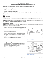
2 MODEL AND SERIAL NUMBER
NOTE: Right hand (RH) and Left-hand (LH) designations are determined from the Operator’s position, facing
forward.
Record the Model Number, Serial Number, and Model Year of the Header, Slow Speed Transport/Stabilizer Wheel
Option (if installed), and the Combine Adapter on the lines below:
HEADER MODEL______________SERIAL NO._________________YEAR_____
Serial Number Plate is located on the left hand endsheet, near the knife
drive motor.
ADAPTER MODEL________SERIAL NO.______________YEAR_____
Serial Number Plate is located on the frame above the main
drive gearbox.
SLOW SPEED TRANSPORT/STABILIZER WHEEL OPTION
SERIAL NO.__________________YEAR_____
Serial Number Plate is located on the left hand wheel pivot tube.

TABLE OF CONTENTS
Form 169006 3 Revision D
Section/Title Page
1
INTRODUCTION ............................................................................................................................................. 1
2 MODEL AND SERIAL NUMBER .................................................................................................................... 2
3 SAFETY ........................................................................................................................................................... 7
3.1 SAFETY ALERT SYMBOL .................................................................................................................... 7
3.2 SIGNAL WORDS................................................................................................................................... 7
3.3 SAFETY DECALS ................................................................................................................................. 7
3.3.1 Safety Decal Installation ............................................................................................................... 7
3.3.2 Safety Decal Locations ................................................................................................................. 8
3.4 GENERAL SAFETY ............................................................................................................................ 20
4 DEFINITIONS ................................................................................................................................................ 22
5 COMPONENT IDENTIFICATION .................................................................................................................. 23
5.1 COMBINE HEADER ............................................................................................................................ 23
5.2 COMBINE ADAPTER .......................................................................................................................... 24
6 SPECIFICATIONS ......................................................................................................................................... 25
7 HEADER ATTACHMENT / DETACHMENT ................................................................................................. 27
7.1 ADAPTER SET-UP ............................................................................................................................. 27
7.1.1 Center-Link Kit ............................................................................................................................ 27
7.1.2 Flighting Extensions .................................................................................................................... 28
7.1.3 Stripper Bars ............................................................................................................................... 28
7.1.4 CR Feeder Deflectors ................................................................................................................. 29
7.1.5 Auger Drive ................................................................................................................................. 29
7.2 CASE IH 7010, 8010, 7120, 8120, 5088, 6088, 7088 .......................................................................... 30
7.2.1 Attachment .................................................................................................................................. 30
7.2.2 Detachment ................................................................................................................................. 32
7.3 CASE IH 2300, 2500 SERIES ............................................................................................................. 34
7.3.1 Attachment .................................................................................................................................. 34
7.3.2 Detachment ................................................................................................................................. 37
7.4 JOHN DEERE 60, 70 SERIES ............................................................................................................. 40
7.4.1 Attachment .................................................................................................................................. 40
7.4.2 Detachment ................................................................................................................................. 42
7.5 JOHN DEERE 50 SERIES .................................................................................................................. 44
7.5.1 Attachment .................................................................................................................................. 44
7.5.2 Detachment ................................................................................................................................. 46
7.6 CAT LEXION 400, 500 SERIES .......................................................................................................... 48
7.6.1 Attachment .................................................................................................................................. 48
7.6.2 Detachment ................................................................................................................................. 51
7.7 NEW HOLLAND CR, CX ..................................................................................................................... 54
7.7.1 Attachment .................................................................................................................................. 54
7.7.2 Detachment ................................................................................................................................. 56
7.8 AGCO .................................................................................................................................................. 58
7.8.1 Attachment .................................................................................................................................. 58
7.8.2 Detachment ................................................................................................................................. 61
8 HEADER/ADAPTER DISASSEMBLY AND ASSEMBLY ............................................................................ 63
8.1 D50 AND D60 HARVEST HEADER/ADAPTER .................................................................................. 63
8.1.1 Disassembly ................................................................................................................................ 63
8.1.2 Assembly ..................................................................................................................................... 66
8.2 FD70 FLEXDRAPER/ADAPTER ......................................................................................................... 71
8.2.1 Disassembly ................................................................................................................................ 71

TABLE OF CONTENTS
Form 169006 4 Revision D
8.2.2 Assembly ..................................................................................................................................... 75
9 OPERATION .................................................................................................................................................. 79
9.1 OWNER/OPERATOR RESPONSIBILITIES ........................................................................................ 79
9.2 OPERATIONAL SAFETY .................................................................................................................... 79
9.3 BREAK-IN PERIOD ............................................................................................................................. 80
9.4 PRE-SEASON CHECK ........................................................................................................................ 80
9.5 DAILY START-UP CHECK .................................................................................................................. 81
9.6 SHUTDOWN PROCEDURE ................................................................................................................ 81
9.7 HEADER CONTROLS ......................................................................................................................... 82
9.8 HEADER LIFT CYLINDER LOCK-OUTS............................................................................................. 82
9.9 REEL PROPS ...................................................................................................................................... 82
9.10 STORAGE ........................................................................................................................................... 84
9.11 HEADER SET-UP ................................................................................................................................ 85
9.11.1 Header Operating Variables ........................................................................................................ 89
9.11.2 Cutting Height .............................................................................................................................. 89
9.11.3 Header Float ................................................................................................................................ 92
9.11.4 Header Angle ............................................................................................................................... 96
9.11.5 Reel Speed .................................................................................................................................. 97
9.11.6 Ground Speed ............................................................................................................................. 98
9.11.7 Draper Speed .............................................................................................................................. 99
9.11.8 Knife Speed ............................................................................................................................... 100
9.11.9 Reel Height ................................................................................................................................ 100
9.11.10 Reel Fore-Aft Position ............................................................................................................... 101
9.11.11 Reel Tine Pitch .......................................................................................................................... 105
9.11.12 Crop Dividers and Rods ............................................................................................................ 107
9.12 DRAPER DEFLECTORS ................................................................................................................... 110
9.12.1 Deflector Replacement .............................................................................................................. 110
9.12.2 Deflector Rework ....................................................................................................................... 110
9.13 KNIFE HEAD SHIELD ....................................................................................................................... 111
9.14 HEADER LEVELLING ....................................................................................................................... 112
9.15 UNPLUGGING CUTTERBAR ............................................................................................................ 113
9.16 UNPLUGGING ADAPTER ................................................................................................................. 113
9.17 UPPER CROSS AUGER ................................................................................................................... 114
9.18 TRANSPORTING HEADER .............................................................................................................. 115
9.18.1 On the Combine ........................................................................................................................ 115
9.18.2 Towing ....................................................................................................................................... 115
9.18.3 Converting from Transport to Field Position .............................................................................. 116
9.18.4 Converting from Field to Transport Position .............................................................................. 121
9.19 WINDROWING .................................................................................................................................. 124
9.19.1 Adapter Modification .................................................................................................................. 124
10 MAINTENANCE AND SERVICING ......................................................................................................... 128
10.1 PREPARATION FOR SERVICING .................................................................................................... 128
10.2 RECOMMENDED SAFETY PROCEDURES .................................................................................... 128
10.3 MAINTENANCE SPECIFICATIONS .................................................................................................. 129
10.3.1 Recommended Torques ............................................................................................................ 129
10.3.2 Roller Chain Installation............................................................................................................. 132
10.3.3 Sealed Bearing Installation ........................................................................................................ 132
10.3.4 Recommended Fluids and Lubricants ....................................................................................... 133
10.3.5 Conversion Chart ....................................................................................................................... 134
10.4 ENDSHIELDS AND COVERS ........................................................................................................... 135
10.4.1 Endshields ................................................................................................................................. 135
10.4.2 Linkage Cover (FD70 FLEXDRAPER ONLY) ........................................................................... 138

TABLE OF CONTENTS
Form 169006 5 Revision D
10.5
LUBRICATION .................................................................................................................................. 139
10.5.1 Greasing Procedure .................................................................................................................. 139
10.5.2 Lubrication Points ...................................................................................................................... 139
10.5.3 Oiling Requirements.................................................................................................................. 147
10.5.4 Auger Drive Chain Lubrication .................................................................................................. 148
10.5.5 Main Drive Gearbox Lubrication ............................................................................................... 148
10.6 HYDRAULICS ................................................................................................................................... 150
10.6.1 Reservoir ................................................................................................................................... 150
10.6.2 Hydraulic Oil Filter ..................................................................................................................... 152
10.6.3 Hoses and Lines ....................................................................................................................... 152
10.6.4 Hydraulic Schematics................................................................................................................ 153
10.7 ELECTRICAL .................................................................................................................................... 156
10.8 MAIN DRIVE ...................................................................................................................................... 156
10.8.1 Driveline Removal ..................................................................................................................... 156
10.8.2 Driveline Installation .................................................................................................................. 157
10.8.3 Guard Removal ......................................................................................................................... 157
10.8.4 Guard Installation ...................................................................................................................... 158
10.8.5 Drive Chain Adjustment ............................................................................................................ 159
10.9 AUGER .............................................................................................................................................. 160
10.9.1 Auger Pan Clearance ................................................................................................................ 160
10.9.2 Auger Drive Chain Adjustment .................................................................................................. 161
10.9.3 Auger Drive Chain Replacement .............................................................................................. 162
10.9.4 Auger Tine Replacement .......................................................................................................... 163
10.10 VIBRATION DAMPERS .................................................................................................................... 165
10.10.1 Rubber Pad Replacement ......................................................................................................... 165
10.11 SICKLE AND SICKLE DRIVE ............................................................................................................ 166
10.11.1 Sickle Sections .......................................................................................................................... 166
10.11.2 Sickle Removal ......................................................................................................................... 167
10.11.3 Sickle Head Bearing Replacement ........................................................................................... 167
10.11.4 Sickle Installation ...................................................................................................................... 168
10.11.5 Spare Sickle (Single Knife Headers) ......................................................................................... 168
10.11.6 Sickle Guards ............................................................................................................................ 169
10.11.7 Sickle Hold-Downs .................................................................................................................... 172
10.11.8 Sickle Drive Belts: Non-Timed Drive ......................................................................................... 173
10.11.9 Double Knife Drive Belts: Timed Drive ...................................................................................... 174
10.11.10 Wobble Box ............................................................................................................................... 179
10.12 ADAPTER FEED DRAPER ............................................................................................................... 182
10.12.1 Draper Tension Adjustment ...................................................................................................... 182
10.12.2 Replacing Draper ...................................................................................................................... 182
10.13 HEADER DRAPERS ......................................................................................................................... 184
10.13.1 Header Draper Tension Adjustment ......................................................................................... 184
10.13.2 Replacing Split Draper .............................................................................................................. 184
10.13.3 Header Draper Alignment ......................................................................................................... 186
10.13.4 Draper Roller Maintenance ....................................................................................................... 187
10.13.5 Deck Height ............................................................................................................................... 190
10.14 REEL AND REEL DRIVE .................................................................................................................. 191
10.14.1 Reel Clearance to Cutterbar: D50, D60 .................................................................................... 191
10.14.2 Reel Clearance to Cutterbar: FD70 .......................................................................................... 192
10.14.3 Reel Frown Adjustment ............................................................................................................. 194
10.14.4 Reel Centering .......................................................................................................................... 194
10.14.5 Reel Drive Chain: D60, FD70 ................................................................................................... 195
10.14.6 Reel Drive Chain: D50 .............................................................................................................. 199
10.14.7 Reel Drive Sprocket: D60, FD70 ............................................................................................... 200
10.14.8 Reel Drive Sprocket: D50 ......................................................................................................... 201
10.14.9 Reel Drive U-Joint: D60, FD70 ONLY ....................................................................................... 202

TABLE OF CONTENTS
Form 169006 6 Revision D
10.14.10 Reel Drive Motor: D60, FD70 .................................................................................................... 203
10.14.11 Reel Drive Motor: D50 ............................................................................................................... 204
10.14.12 Reel Speed Sensor ................................................................................................................... 205
10.14.13 Reel Tines ................................................................................................................................. 208
10.14.14 Tine Tube Bushings ................................................................................................................... 210
10.15 HEADER WING FLOAT ..................................................................................................................... 214
10.15.1 Wing Float Lock Adjustment ...................................................................................................... 214
10.15.2 Wing Balance ............................................................................................................................ 214
10.15.3 Wing Linkage Adjustment .......................................................................................................... 216
10.16 TRANSPORT SYSTEM ..................................................................................................................... 217
10.16.1 Wheel Bolt Torque ..................................................................................................................... 217
10.16.2 Axle Bolts ................................................................................................................................... 217
10.16.3 Tire Inflation ............................................................................................................................... 217
10.17 MAINTENANCE SCHEDULE ............................................................................................................ 218
10.17.1 Break-In Inspections .................................................................................................................. 218
10.17.2 Interval Maintenance ................................................................................................................. 219
10.17.3 Maintenance Record ................................................................................................................. 220
11 TROUBLESHOOTING ............................................................................................................................. 222
11.1 CROP LOSS AT CUTTERBAR .......................................................................................................... 222
11.2 CUTTING ACTION AND SICKLE COMPONENTS ........................................................................... 223
11.3 REEL DELIVERY ............................................................................................................................... 225
11.4 HEADER AND DRAPERS ................................................................................................................. 227
11.5 FD70 FLEXDRAPER ......................................................................................................................... 229
11.6 CUTTING EDIBLE BEANS ................................................................................................................ 230
12 OPTIONS AND ATTACHMENTS ............................................................................................................ 234
12.1 AUTO HEADER HEIGHT CONTROLLER ......................................................................................... 234
12.2 KNIFE REVERSING KIT .................................................................................................................... 234
12.3 FLOAT/ANGLE INDICATOR ............................................................................................................. 234
12.4 HYDRAULIC HEADER TILT .............................................................................................................. 234
12.5 CUTTERBAR POLY .......................................................................................................................... 235
12.6 ADJUSTABLE SKID SHOES WITH POLY COVER ........................................................................... 235
12.7 STUB GUARD CONVERSION KIT .................................................................................................... 235
12.8 STABILIZER WHEELS ...................................................................................................................... 235
12.9 STABILIZER/TRANSPORT WHEELS ............................................................................................... 235
12.10 LODGED CROP REEL FINGER KIT ................................................................................................. 236
12.11 VERTICAL KNIFE MOUNTS ............................................................................................................. 236
12.12 UPPER CROSS AUGER ................................................................................................................... 236
12.13 REEL ENDSHIELD KIT ..................................................................................................................... 236
12.14 ROCK RETARDER KIT ..................................................................................................................... 237
12.15 RICE DIVIDER KIT ............................................................................................................................ 237
12.16 HYDRAULIC REEL FORE-AFT POSITIONER .................................................................................. 237
12.17 CA20 DELICATE SEED SAVER KIT ................................................................................................. 237
12.18 KNIFE HEAD SHIELD ....................................................................................................................... 237
13 UNLOADING AND ASSEMBLY .............................................................................................................. 238
INDEX …………………………………………………………………………………….……………....………………...239

SECTION 3. SAFETY
Form 169006 7 Revision D
3 SAFETY
3.1 SAFETY ALERT SYMBOL
This safety alert symbol indicates important safety
messages in this manual and on safety decals on the
machine.
This symbol means:
ATTENTION!
BECOME ALERT!
YOUR SAFETY IS INVOLVED!
Carefully read and follow the safety message
accompanying this symbol.
WHY IS SAFETY IMPORTANT TO YOU?
ACCIDENTS DISABLE AND KILL.
ACCIDENTS COST.
ACCIDENTS CAN BE AVOIDED.
3.2 SIGNAL WORDS
Note the use of the signal words DANGER,
WARNING, and CAUTION with safety messages.
The appropriate signal word for each message has
been selected using the following guidelines:
DANGER
Indicates an imminently hazardous situation
that, if not avoided, will result in death or
serious injury.
WARNING
Indicates a potentially hazardous situation
that, if not avoided, could result in death or
serious injury. It is also used to alert against
unsafe practices.
CAUTION
Indicates a potentially hazardous situation
that, if not avoided, may result in minor or
moderate injury. It is also used as a reminder
of good safety practices.
3.3 SAFETY DECALS
The safety decals appear on the header at
the locations shown on pages 8 to 19.
Keep safety decals clean and legible at all
times.
Replace safety decals that are missing or
become illegible.
If original parts on which a safety decal was
installed are replaced, be sure the repair part
also bears the current safety decal.
Safety decals are available from your
MacDon Dealer Parts Department.
3.3.1 Safety Decal Installation
a. Be sure the installation area is clean and dry.
b. Decide on the exact location before you remove
the decal backing paper.
c. Remove the smaller portion of the split backing
paper.
d. Place the decal in position and slowly peel back
the remaining paper, smoothing the decal as it is
applied.
e. Small air pockets can be smoothed out or pricked
with a pin.

SECTION 3. SAFETY
Form 169006 8 Revision D
3.3.2 Safety Decal Locations
3.3.2.1 3-Panel Safety Decals: North America
BACK TUBE - BOTH ENDS
#172147
BACK TUBE #134070
BACK TUBE #134070
D60 45 FT
FD70
BACK TUBE #42122

SECTION 3. SAFETY
Form 169006 9 Revision D
3-Panel Safety Decals: North America (Cont’d)
A
LL
D60 20 FT
BACK TUBE #109843
BACK TUBE #134070
BACK TUBE & DECKS #172147

SECTION 3. SAFETY
Form 169006 10 Revision D
3-Panel Safety Decals: North America (Cont’d)
D50, D60: 30, 35, 40 FT D60 25 FT
BACK TUBE BOTH ENDS
#172147
BACK TUBE #134070
BACK TUBE - DOUBLE REEL ONLY
#42122

SECTION 3. SAFETY
Form 169006 11 Revision D
3-Panel Safety Decals: North America (Cont’d)
ALL
D60, FD70
BOTH ENDS - DOUBLE KNIFE
LEFT END - SINGLE KNIFE
#142909
D50
D50
REEL ARMS
#174633
LH & RH REEL ARMS
#174633
LH & RH REEL ARMS
#42122

SECTION 3. SAFETY
Form 169006 12 Revision D
3-Panel Safety Decals: North America (Cont’d)
DRIVELINE
#30316
INSIDE DRIVELINE GUARD
#36651

SECTION 3. SAFETY
Form 169006 13 Revision D
3.3.2.2 2-Panel Safety Decals: North America
and Export
ALL
FRONT TRANSPORT LEG
#193147
TOW-BAR
#129261
TOW-BAR
#193113

SECTION 3. SAFETY
Form 169006 14 Revision D
2-Panel Safety Decals: North America and Export
(Cont’d)
UPPER CROSS AUGER
#174682
LH AND RH
VERTICAL KNIFE
#174684

SECTION 3. SAFETY
Form 169006 15 Revision D
3.3.2.3 2-Panel Safety Decals: Export
BOTH ENDS #113482
BOTH ENDS - DOUBLE KNIFE
LEFT END - SINGLE KNIFE
#184371
BOTH ENDS #174436
DRIVELINE
#194521
ALL

SECTION 3. SAFETY
Form 169006 16 Revision D
2-Panel Safety Decals: Export (Cont’d)
BACKTUBE #174474
BACKTUBE - BOTH ENDS #174434
BACKTUBE #174474
D6045FT
FD70
BACKTUBE #174432

SECTION 3. SAFETY
Form 169006 17 Revision D
2-Panel Safety Decals: Export (Cont’d)
D60 20 FT
BACKTUBE #174474
BOTH ENDS #113482
ALL
BACKTUBE AND DECKS #174434

SECTION 3. SAFETY
Form 169006 18 Revision D
2-Panel Safety Decals: Export (Cont’d)
D50, D60: 30, 35, 40 FT D60 25 FT
BACK TUBE - BOTH ENDS
#174434
BACK TUBE - DOUBLE REEL ONLY
#174432
BACK TUBE - BOTH ENDS
#174474
/