Page is loading ...

293 Wright Street, Delavan, WI 53115
Phone: 1-800-365-6832
Fax: 1-800-526-3757
Web Site: flotecwater.com
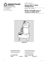
OWNER’S MANUAL
Submersible Sump Pumps
NOTICE D’UTILISATION
Pompes submersibles
pour puisard
MANUAL DEL USUARIO
Bombas sumergibles
para sumideros y efluentes
Installation/Operation/Parts
For further operating,
installation, or maintenance
assistance:
Call 1-800-365-6832
English ...................... Pages 2-7
Installation/Fonctionnement/Pièces
Pour plus de renseignements
concernant l’utilisation,
l’installation ou l’entretien,
Composer le
1 (800) 365-6832
Français ................ Pages 8-12
Instalación/Operación/Piezas
Para mayor información sobre
el funcionamiento, instalación o
mantenimiento de la bomba:
Llame al 1-800-365-6832
Español ............... Paginas 13-19
©2010 FP916 (11/18/10)
FPSC3350A

DESCRIPTION
This Submersible Sump Pump is designed for
home sumps. The unit is equipped with a 3-prong
grounding-type power cord. The shaded-pole motor
is oil filled and sealed for cooler running. The upper
sleeve/lower ball bearings on the motor shaft never
need lubrication. Automatic reset thermal protection
is provided.
NOTICE This unit is not designed as a waterfall
or fountain pump, or for applications involving salt
water or brine! Use with waterfalls, fountains, salt
water or brine will void warranty.
Do not use where water recirculates or as a
swimming pool drainer.
NOTICE Read this Owner’s Manual for installation,
operation, and safety information. Keep for future use.
SPECIFICATIONS
Power supply required ...........................115V, 60 HZ.
Liquid Temp. Range .............32°F to 130°F (0°-54°C)
Individual Branch Circuit Required (min.) .... 15 Amps
Discharge: .................................................1-1/2” NPT
NOTICE Do not reduce size of discharge pipe or
hose below 1-1/4” diameter. If discharge is too
small, pump will overheat and fail prematurely.
This pump is designed for use in a residential sump
only. Pump water only with this pump.
PERFORMANCE
MOTOR & CORD SPECIFICATIONS
GENERAL SAFETY INFORMATION
Electrically powered sump pumps normally give
many years of trouble-free service when correctly
installed, maintained, and used. However, unusual
circumstances (interruption of power to the pump,
dirt/debris in the sump, flooding that exceeds the
pump’s capacity, electrical or mechanical failure
in the pump, etc.) may prevent your pump from
functioning normally.
To prevent possible water damage due to flooding,
consult your retailer about a secondary AC sump
pump, a DC backup sump pump, and/or a high
water alarm. See the “Troubleshooting Chart” in
this manual for information about common sump
pump problems and remedies. For more information,
see your retailer, call Flotec customer service at
1-800-365-6832 or visit flotecwater.com.
1. Know the pump application, limitations, and
potential hazards.
2. Do not use in water with fish present. If any oil
leaks out of the motor it can kill fish.
3. Disconnect power before servicing.
4. Release all pressure within system before
servicing any component.
5. Drain all water from system before servicing.
6. Secure discharge line before starting pump. An
unsecured discharge line will whip, possibly
causing personal injury and/or property damage.
7. Check hoses for weak or worn condition before
each use, making certain that all connections are
secure.
8. Periodically inspect sump, pump and system
components. Keep free of debris and foreign
objects. Perform routine maintenance as
required.
9. Provide means of pressure relief for pumps whose
discharge line can be shut-off or obstructed.
10. Personal Safety:
a. Wear safety glasses at all times when working
with pumps.
b. Keep work area clean, uncluttered and
properly lighted – replace all unused tools
and equipment.
c. Keep visitors at a safe distance from work area.
d. Make workshop child-proof – with padlocks,
master switches, and by removing starter keys.
11. When wiring an electrically driven pump, follow
all electrical and safety codes that apply.
For parts or assistance, call Flotec Customer Service at 1-800-365-6832
Specifications and Safety 2
Motor
HP
Full
Load
Amps
Individual Branch Circuit
Required (Amps)
Cord
Length
1/3 9.8 15 10’ (3 m)
GPH (LPH) At Total Feet (m) of Lift
5
(1.5 m)
10
(3 m)
15
(4.6 m)
20
(6.1 m)
No flow
at height
shown
below
Capacity–Gallons(L)/Hour
2,880
(10,902)
2,400
(9,085)
1,740
(6,587)
900
(3,407)
24 Ft.
(7.3 m)

For parts or assistance, call Flotec Customer Service at 1-800-365-6832
Installation 3
12. This equipment is only for use on 115 volt
(single phase) and is equipped with an
approved 3-conductor cord and 3-prong,
grounding-type plug.
Electrical Shock Hazard. Can burn
or kill. To reduce risk of electric shock, pull plug
before servicing. This pump has not been
investigated for use in swimming pool areas.
Pump is supplied with a grounding conductor
and grounding-type attachment plug. Be sure it is
connected only to a properly grounded
grounding-type receptacle.
Where a 2-prong wall receptacle is encountered,
it must be replaced with properly grounded
3-prong receptacle installed in accordance with
codes and ordinances that apply.
13. All wiring should be performed by a qualified
electrician.
14. Make certain power source conforms to
requirements of your equipment.
15. Protect electrical cord from sharp objects, hot
surfaces, oil, and chemicals. Avoid kinking
cord. Replace or repair damaged or worn cords
immediately.
16. Do not touch an operating motor. Motors can
operate at high temperatures.
17. Do not handle pump or pump motor with wet
hands or when standing on wet or damp surface,
or in water.
Hazardous voltage can shock, burn
or kill. If your basement has water or moisture
on floor, do not walk on wet area until all power
has been turned off. If shut-off box is in
basement, call electric company or hydro
authority to shut-off service to house, or call
your local fire department for instructions.
Remove pump and repair or re place. Failure to
follow this warning can result in fatal electrical
shock.
Do not lift pump by power cord.
INSTALLATION
1. Install pump in sump pit with minimum diameter
of 11” (28 cm). Sump depth should be 15”
(39 cm). Construct sump pit of tile, concrete,
steel or plastic. Check local codes for approved
materials and for proper installation.
2. Install pump in pit so that switch operating
mechanism has maximum possible clearance.
Adjust the float stop on the rod to adjust the
pump “ON” point. “OFF” point is factory preset.
3. Pump should not be installed on clay, earth or
sand surfaces. Clean sump pit of small stones
and gravel which could clog pump. Keep pump
inlet screen clear.
NOTICE Do not use ordinary pipe joint
compound on plastic pipe. Pipe joint compound
can attack plastics.
4. Install discharge plumbing. Use rigid plastic pipe
and wrap threads with
1
Teflon
™
tape. Screw pipe
into pump hand tight plus 1-1/2 turns.
Risk of flooding. If a flexible
discharge hose is used, make sure pump is
secured in sump to prevent movement. Failure to
secure pump may allow pump movement, switch
interference and prevent pump from starting or
stopping.
5. To reduce motor noise and vibrations, a short
length of rubber hose (1-7/8” (47.6mm) I. D.,
e.g. radiator hose) can be connected into
discharge line near pump using suitable clamps.
6. Install an in-line check valve (part number
FP0026-10-P2) to prevent flow backwards
through pump when pump shuts off. If using the
pump in anything other than a sump application,
ensure in-line check valve is installed horizontally.
1
E.I. DuPont De Nemours and Company Corporation, Delaware.

For parts or assistance, call Flotec Customer Service at 1-800-365-6832
7. Power Supply: The pump is designed for 115 V.,
60 Hz., operation and requires a minimum
15 amp individual branch circuit. The pump is
supplied with a 3-wire cord set with grounding-
type plug. Be sure it is connected only to a
properly grounded grounding-type receptacle.
Hazardous voltage. Can shock,
burn or kill. The pump should always be
electrically grounded to a suitable electrical
ground such as a grounded water pipe or a
properly grounded metallic raceway, or ground
wire system. Do not modify the cord or plug or
cut off the round ground pin.
8. If pump discharge line is exposed to outside
sub-freezing atmosphere, portion of line exposed
must be installed so any water remaining in pipe
will drain to the outfall by gravity. Failure to do
this can cause water trapped in discharge to
freeze which could result in damage to pump.
9. After piping, check valve and float switch have
been installed, the unit is ready for operation.
10. Check the pump operation by filling sump with
water and observing pump operation through
one complete cycle.
Risk of Flooding. Failure to make
this operational check may lead to improper
operation, premature failure, and flooding.
OPERATION
Risk of electrical shock. Can burn or
cause death. Do not handle a pump or pump motor
with wet hands or when standing on wet or damp
surface, or in water. Before attempting to check why
unit has stopped operating, disconnect power from
unit.
1. Shaft seal depends on water for lubrication.
Do not operate pump unless it is submerged
in water as seal may be damaged if allowed to
run dry.
2. Motor is equipped with automatic reset thermal
protector. If temperature in motor should rise
unduly, switch will cut off all power before
damage can be done to motor. When motor has
cooled sufficiently, switch will reset automatically
and restart motor. If protector trips repeatedly,
pump should be removed and checked as to
cause of difficulty. Low voltage, long extension
cords, clogged impeller, very low head or lift, or
a plugged or frozen discharge pipe, etc., could
cause cycling.
3. Pump will not remove all water. If operating a
pump manually, and suddenly no water comes
out of the discharge hose, shut off the unit
immediately. The water level is probably very low
and the unit has broken prime.
Risk of electric shock. Before
attempting to check why unit has stopped
operating, disconnect power from unit.
Airlock
When a pump airlocks, it runs but does not move
any water. An airlock will cause the pump to overheat
and fail. This pump has a built in anti-airlock hole
(see Repair Parts diagram). Water leakage from the
anti-airlock hole is normal.
If you suspect an airlock, unplug the pump, clean out
the anti-airlock hole with a paper clip or a piece of
wire, and restart the pump.
Installation and Operation 4

For parts or assistance, call Flotec Customer Service at 1-800-365-6832
Repair Parts 5
anti-airlock hole
2A
2B
3
4
6
2C
9
5868 0910
**If motor fails, replace entire pump.
Key No. Description Qty.
2 Gasket Kit (Includes O-Rings and Gaskets, Key Nos. 2A,2B, 2C) 1 U9-471REP
3 Power Cord 10’ 1 PW117-237-TSU
4 Motor 1 *
6 Impeller 1 PS5-26P
9 Switch Float Kit (Includes Float, Switch Rod, Rod Stops and
Tether Strap)
1 PS28-37REP

For parts or assistance, call Flotec Customer Service at 1-800-365-6832
Troubleshooting 6
TROUBLESHOOTING CHART
SYMPTOM PROBABLE CAUSE(S) CORRECTIVE ACTION
Pump won’t start or run. Pump is not plugged in. Check and see if pump is plugged in to a proper outlet.
Blown fuse. If blown, replace with fuse of proper size.
Low line voltage. If voltage under recommended minimum, check size of wiring
from main switch on property. If OK, contact power company
or hydro authority.
Defective motor. Replace pump.
Defective float switch. Replace float switch.
Impeller. If impeller won’t turn, remove lower pump body and locate
source of binding.
Float obstructed. Remove obstruction.
Pump starts and stops Backflow of water from piping. Install or replace check-valve.
too often.
Faulty float switch. Replace float switch.
Pump won’t shut off. Defective float switch. Replace float switch.
Restricted discharge Remove pump and clean pump and piping.
(obstacle or ice in piping).
Float obstructed. Remove obstruction.
Restricted intake screen. Remove the pump and clean the intake screen and the
impeller.
Pump operates but Low line voltage. If voltage under recommended minimum, check size of wiring
delivers little or no water. from main switch on property. If OK, contact power company
or hydro authority.
Something caught in impeller. Remove the pump and clean out the impeller.
Worn or defective parts or Clean impeller if plugged; otherwise replace pump.
plugged impeller.
Check valve installed without Drill a 1/16” - 1/8” (1.6mm - 3.2mm) dia. hole between pump
vent hole. discharge & check valve (1-2” above where the discharge
pipe screws into the pump discharge and below the
waterline).
Restricted intake screen. Remove the pump and clean out the intake screen.
Check valve is installed either Be sure check valve is installed correctly.
backward or upside down.

Warranty 7
RETAIN ORIGINAL RECEIPT FOR YOUR RECORDS.
LIMITED WARRANTY
FLOTEC warrants to the original consumer purchaser (“Purchaser” or “You”) of its products that they are free from
defects in material and workmanship for a period of twelve (12) months from the date of the original consumer purchase.
If, within twelve (12) months from the original consumer purchase, any such product shall prove to be defective, it
shall be repaired or replaced at FLOTEC’s option, subject to the terms and conditions set forth below. The original
purchase receipt and product warranty information label are required to determine warranty eligibility. Eligibility is
based on purchase date of original product – not the date of replacement under warranty. The warranty is limited to
repair or replacement of product only – Purchaser pays all removal, installation, labor, shipping, and incidental charges.
For parts or troubleshooting assistance, DO NOT return product to your retail store. Contact FLOTEC Customer Service
at 1-800-365-6832.
Claims made under this warranty shall be made by returning the product (except sewage pumps, see below) to the
retail outlet where it was purchased immediately after the discovery of any alleged defect. FLOTEC will subsequently
take corrective action as promptly as reasonably possible. No requests for service will be accepted if received more
than 30 days after the warranty expires.
Warranty does not apply to products used in commercial/rental applications.
SEWAGE PUMPS
DO NOT return a sewage pump (that has been installed) to your retail store. Contact FLOTEC Customer Service. Sewage
pumps that have seen service and been removed carry a contamination hazard with them.
If your sewage pump has failed:
• Wearrubbergloveswhenhandlingthepump;
• Forwarrantypurposes,returnthepump’scordtagandoriginalreceiptofpurchasetotheretailstore;
• Disposeofthepumpaccordingtolocaldisposalordinances.
Exceptions to the Twelve (12) Month Limited Warranty
Product Warranty Period
Drill Pump, Pitcher Pump, In-line Water Filter Cartridge,
90 days
Utility Pump (Models FP0F360AC, FP0FDC)
1/3 HP Submersible Sump Pumps,
Pool Cover Pump (Model FP0S1790PCA), Utility Pump (Model FP0S4100X),
2 Years
Condensate Pump (Model FPCP-20ULST),
IntellIPumP (Model FP0S1775A),
Back-up Sump Pump System (Model FP2800DCC)
4” Submersible Well Pumps, 1/2 HP Submersible Sump Pumps,
3 Years
1/3 HP Sump Pump (Models FPSC2200A-10, FPSC2250A-10)
Pre-Charge Water System Tank (FP7100 Series),
1/2 HP Sump Pump (Models FPSC3200A-10, FPSC3250A-10),
5 Years
Submersible Solids Handling Pumps (Models FPSE9000, E75STVT),
Submersible Sump Pumps (Models E50TLT, E50VLT, E75VLT, E100ELT, FPSC5000A)
Floodmate
®
7000 (Model FP0S6000A), Pedestal Sump Pump (Model FPPSS5000),
Sewage Ejector (Model FPSE3601A), Submersible Sewage Pump (Model FPSES2700A), Lifetime
Utility Pump (Model FPSC1725X), Submersible Sump Pump (Model FPSC4550A-10)
General Terms and Conditions
You must pay all labor and shipping charges necessary to replace product covered by this warranty. This warranty
doesnotapplytothefollowing:(1)actsofGod;(2)productswhich,inFLOTEC’ssolejudgement,havebeensubjectto
negligence,abuse,accident,misapplication,tampering,oralteration;(3)failuresduetoimproperinstallation,operation,
maintenanceorstorage;(4)atypicalorunapprovedapplication,useorservice;(5)failurescausedbycorrosion,rust
or other foreign materials in the system, or operation at pressures in excess of recommended maximums.
This warranty sets forth FLOTEC’s sole obligation and purchaser’s exclusive remedy for defective products.
FLOTEC SHALL NOT BE LIABLE FOR ANY CONSEQUENTIAL, INCIDENTAL, OR CONTINGENT DAMAGES WHATSOEVER.
THE FOREGOING WARRANTIES ARE EXCLUSIVE AND IN LIEU OF ALL OTHER EXPRESS AND IMPLIED WARRANTIES,
INCLUDING BUT NOT LIMITED TO THE IMPLIED WARRANTIES OF MERCHANTABILITY AND FITNESS FOR A PARTICULAR
PURPOSE. THE FOREGOING WARRANTIES SHALL NOT EXTEND BEYOND THE DURATION PROVIDED HEREIN.
Some states do not allow the exclusion or limitation of incidental or consequential damages or limitations on how long
an implied warranty lasts, so the above limitations or exclusions may not apply to You. This warranty gives You specific
legal rights and You may also have other rights which vary from state to state.
FLOTEC • 293 Wright Street • Delavan, WI U.S.A. 53115
Phone: 1-800-365-6832 • Fax: 1-800-526-3757
Web Site: flotecwater.com
/