Hitachi DH 40FA Instruction And Safety Manual
- Category
- Power tools
- Type
- Instruction And Safety Manual

DH 40FA
MODEL ROTARY HAMMER
MODÈLE MARTEAU ROTATIF
MODELO MARTILLO GIRATORIO
DOUBLE INSULATION
DOUBLE ISOLATION
AISLAMIENTO DOBLE
MODE D’EMPLOI ET INSTRUCTIONS DE SECURITE
AVERTISSEMENT
Une utilisation incorrecte et dangereuse de cet outil motorisé peut entraîner la
mort ou de sérieuses blessures corporelles!
Ce mode d’emploi contient d’importantes informations à propos de la sécurité de
ce produit. Prière de lire et de comprendre ce mode d’emploi avant d’utiliser l’outil
motorisé. Garder ce mode d’emploi à la disponibilité des autres utilisateurs avant
qu’ils utilisent l’outil motorisé.
INSTRUCTION MANUAL AND SAFETY INSTRUCTIONS
WARNING
Improper and unsafe use of this power tool can result in death or serious bodily
injury!
This manual contains important information about product safety. Please read
and understand this manual before operating the power tool. Please keep this
manual available for others before they use the power tool.
MANUAL DE INSTRUCCIONES E INSTRUCCIONES DE SEGURIDAD
ADVERTENCIA
¡La utilización inapropiada e insegura de esta herramienta eléctrica puede resultar
en lesiones serias o en la muerte!
Este manual contiene información importante sobre la seguridad del producto.
Lea y comprenda este manual antes de utilizar la herramienta eléctrica. Guarde
este manual para que puedan leerlo otras personas antes de que utilicen la
herramienta eléctrica.

CONTENTS
Page
IMPORTANT INFORMATION ............ 3
MEANINGS OF SIGNAL WORDS ..... 3
SAFETY ...................................................... 4
GENERAL SAFETY RULES.................... 4
SPECIFIC SAFETY RULES AND
SYMBOLS........................................... 7
DOUBLE INSULATION FOR SAFER
OPERATION ....................................... 8
FUNCTIONAL DESCRIPTION.................... 9
MANE OF PARTS................................... 9
SPECIFICATIONS ................................... 9
Page
ASSEMBLY AND OPERATION ............... 10
APPLICATIONS .................................... 10
PRIOR TO OPERATION ....................... 10
HOW TO USE ....................................... 11
HOW TO USE THE CORE BIT ............. 13
MAINTENANCE AND INSPECTION ....... 15
ACCESSORIES ......................................... 17
STANDARD ACCESSORIES ................ 17
OPTIONAL ACCESSORIES.................. 17
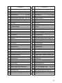
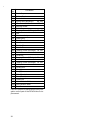
PARTS LIST.............................................. 52
TABLE DES MATIERES
Page
INFORMATIONS IMPORTANTES ....... 19
SIGNIFICATION DES MOTS
D’AVERTISSEMENT ........................ 19
SECURITE ................................................ 20
REGLES GENERALES DE SECURITE
... 20
REGLES DE SECURITE SPECIFIQUES
ET SYMBOLES ................................. 23
DOUBLE ISOLATION POUR UN
FONCTIONNEMENT PLUS SUR ..... 24
DESCRIPTION FONCTIONNELLE ........... 25
NOM DES PARTIES ............................. 25
SPECIFICATIONS ................................. 25
Page
ASSEMBLAGE ET FONCTIONNEMENT ....
26
APPLICATIONS .................................... 26
AVANT L’UTILISATION ....................... 26
UTILISATION ....................................... 27
COMMENT UTILISER LA
COURONNE ..................................... 29
ENTRETIEN ET INSPECTION .................. 31
ACCESOIRES ........................................... 33
ACCESSOIRES STANDARD ................ 33
ACCESSOIRES SUR OPTION.............. 33
LISTA DES PIÈCES .................................. 52
ÍNDICE
Página
INFORMACIÓN IMPORTANTE ........... 35
SIGNIFICADO DE LAS PALABRAS DE
SEÑALIZACIÓN................................ 35
SEGURIDAD............................................. 36
NORMAS GENERALES DE SEGURIDAD
.. 36
NORMAS Y SÍMBOLOS
ESPECÍFICOS DE SEGURIDAD ....... 39
AISLAMIENTO DOBLE PARA OFRECER
UNA OPERACIÓN MÁS SEGURA
.... 40
DESCRIPCIÓN FUNCIONAL.................... 41
NOMENCLATURA ............................... 41
ESPECIFICACIONES ............................ 41
Página
MONTAJE Y OPERACIÓN ...................... 42
APLICACIONES .................................... 42
ANTES DE LA OPERACIÓN ................ 42
MODE DE UTILIZACIÓN...................... 43
MODO DE USAR LA BARRENA
TUBULAR ......................................... 46
MANTENIMIENTO E INSPECCIÓN ........ 48
ACCESORIOS........................................... 50
ACCESORIOS ESTÁNDAR .................. 50
ACCESORIOS OPCIONALES............... 50
LISTA DE PIEZAS .................................... 52
English
Français
Español

3
English
IMPORTANT INFORMATION
Read and understand all of the operating instructions, safety precautions and
warnings in the Instruction Manual before operating or maintaining this power tool.
Most accidents that result from power tool operation and maintenance are caused
by the failure to observe basic safety rules or precautions. An accident can often be
avoided by recognizing a potentially hazardous situation before it occurs, and by
observing appropriate safety procedures.
Basic safety precautions are outlined in the “SAFETY” section of this Instruction
Manual and in the sections which contain the operation and maintenance
instructions.
Hazards that must be avoided to prevent bodily injury or machine damage are
identified by WARNINGS on the power tool and in this Instruction Manual.
Never use this power tool in a manner that has not been specifically recommended
by HITACHI, unless you first confirm that the planned use will be safe for you and
others.
MEANINGS OF SIGNAL WORDS
WARNING indicates a potentially hazardous situations which, if ignored, could result
in serious personal injury.
CAUTION indicates a hazardous situations which, if ignored, could result in moderate
personal injury, or could cause machine damage.
NOTE emphasizes essential information.

4
English
SAFETY
GENERAL SAFETY RULES
WARNING: Read and understand all instructions.
Failure to follow all instructions listed below, may result in electric
shock, fire and/or serious personal injury.
SAVE THESE INSTRUCTIONS
1. Work Area
(1) Keep your work area clean and well lit. Cluttered benches and dark areas
invite accidents.
(2) Do not operate power tools in explosive atmospheres, such as in the presence
of flammable liquids, gases, or dust. Power tools create sparks which may
ignite the dust or fumes.
(3) Keep bystanders, children, and visitors away while operating a power tool.
Distractions can cause you to lose control.
2. Electrical Safety
(1) Double Insulated tools are equipped with a polarized plug (one blade is wider
than the other.) This plug will fit in a polarized outlet only one way. If the
plug does not fit fully in the outlet, reverse the plug. If it still does not fit,
contact a qualified electrician to install a polarized outlet. Do not change the
plug in any way. Double Insulation eliminates the need for the three wire
grounded power cord and grounded power supply system.
(2) Avoid body contact with grounded surfaces such as pipes, radiators, ranges
and refrigerators. There is an increased risk of electric shock if your body is
grounded.
(3) Don’t expose power tools to rain or wet conditions. Water entering a power
tool will increase the risk of electric shock.
(4) Do not abuse the cord. Never use the cord to carry the tools or pull the plug
from a receptacle. Keep cord away from heat, oil, sharp edges or moving
parts. Replace damaged cords immediately. Damaged cords increase the
risk of electric shock.
(5) When operating a power tool outside, use an outdoor extension cord marked
“W-A” or “W”. These cords are rated for outdoor use and reduce the risk of
electric shock.
3. Personal Safety
(1) Stay alert, watch what you are doing and use common sense when operating
a power tool. Do not use tool while tired or under the influence of drugs,
alcohol, or medication. A moment of inattention while operating power tools
may result in serious personal injury.
(2) Dress properly. Do not wear loose clothing or jewelry. Contain long hair.
Keep your hair, clothing, and gloves away from moving parts. Loose clothes,
jewelry, or long hair can be caught in moving parts.

5
English
(3) Avoid accidental starting. Be sure switch is off before plugging in. Carrying
tools with your finger on the switch or plugging in tools that have the switch
on invites accidents.
(4) Remove adjusting keys or wrenches before turning the tool on. A wrench or
a key that is left attached to a rotating part of the tool may result in personal
injury.
(5) Do not overreach. Keep proper footing and balance at all times. Proper footing
and balance enables better control of the tool in unexpected situations.
(6) Use safety equipment. Always wear protective glasses. Dust mask, non-skid
safety shoes, hard hat, or ear plugs must be used for appropriate conditions.
4. Tool Use and Care
(1) Use clamps or other practical way to secure and support the workpiece to a
stable platform. Holding the work by hand or against your body is unstable
and may lead to loss of control.
(2) Do not force tool. Use the correct tool for your application. The correct tool
will do the job better and safer at the rate for which it is designed.
(3) Do not use tool if switch does not turn it on or off. Any tool that cannot be
controlled with the switch is dangerous and must be repaired.
(4) Disconnect the plug form the power source before making any adjustments,
changing accessories, or storing the tool. Such preventive safety measures
reduce the risk of starting the tool accidentally.
(5) Store idle tools out of reach of children and other untrained persons. Tools
are dangerous in the hands of untrained users.
(6) Maintain tools with care. Keep cutting tools sharp and clean. Properly
maintained tools, with sharp cutting edges are less likely to bind and are
easier to control.
(7) Check for misalignment or binding of moving parts, breakage of parts, and
any other condition that may affect the tools operation. If damaged, have
the tool serviced before using. Many accidents are caused by poorly
maintained tools.
(8) Use only accessories that are recommended by the manufacturer for your
model. Accessories that may be suitable for one tool, may become hazardous
when used on another tool.
5. Service
(1) Tool service must be performed only by qualified repair personnel. Service
or maintenance performed by unqualified personnel could result in a risk of
injury.
(2) When servicing a tool, use only identical replacement parts. Follow
instructions in the Maintenance section of this manual. Use of unauthorized
parts or failure to follow Maintenance Instruction may create a risk of electric
shock or injury.
6. Never touch moving parts.
Never place your hands, fingers or other body parts near the tool’s moving parts.
7. Never operate without all guards in place.
Never operate this tool without all guards or safety features in place and in proper
working order. If maintenance or servicing requires the removal of a guard or
safety feature, be sure to replace the guard or safety feature before resuming
operation of the tool.

6
English
8. Use right tool.
Don’t force small tool or attachment to do the job of a heavy-duty tool.
Don’t use tool for purpose not intended — for example — don’t use circular saw
for cutting tree limbs or logs.
9. Never use a power tool for applications other than those specified.
Never use a power tool for applications other than those specified in the
Instruction Manual.
10.Handle tool correctly.
Operate the tool according to the instructions provided herein. Do not drop or
throw the tool. Never allow the tool to be operated by children, individuals
unfamiliar with its operation or unauthorized personnel.
11.Keep all screws, bolts and covers tightly in place.
Keep all screws, bolts, and plates tightly mounted. Check their condition
periodically.
12.Do not use power tools if the plastic housing or handle is cracked.
Cracks in the tool’s housing or handle can lead to electric shock. Such tools
should not be used until repaired.
13.Blades and accessories must be securely mounted to the tool.
Prevent potential injuries to yourself or others. Blades, cutting implements and
accessories which have been mounted to the tool should be secure and tight.
14.Keep motor air vent clean.
The tool’s motor air vent must be kept clean so that air can freely flow at all
times. Check for dust build-up frequently.
15.Operate power tools at the rated voltage.
Operate the power tool at voltages specified on its nameplate.
If using the power tool at a higher voltage than the rated voltage, it will result in
abnormally fast motor revolution and may damage the unit and the motor may
burn out.
16.Never use a tool which is defective or operating abnormally.
If the tool appears to be operating unusually, making strange noises, or otherwise
appears defective, stop using it immediately and arrange for repairs by a Hitachi
authorized service center.
17.Never leave tool running unattended. Turn power off.
Don’t leave tool until it comes to a complete stop.
18.Carefully handle power tools.
Should a power tool be dropped or struck against hard materials inadvertently,
it may be deformed, cracked, or damaged.
19.Do not wipe plastic parts with solvent.
Solvents such as gasolie, thinner, benzine, carbon tetrachloride, and alcohol may
damage and crack plastic parts. Do not wipe them with such solvents.
Wipe plastic parts with a soft cloth lightly dampened with soapy water and dry
thoroughly.

7
English
SPECIFIC SAFETY RULES AND SYMBOLS
1. Hold tools by insulated gripping surfaces when performing an operation where
the cutting tool may contact hidden wiring or its own cord. Contact with a “live”
wire will make exposed metal parts of the tool “live” and shock the operator.
2. Wear ear plugs when using the tool for extended periods. Prolonged exposure
to high intensity noise can cause hearing loss.
3. NEVER touch the tool bit with bare hands after operation.
4. NEVER wear gloves made of stuff liable to roll up such as cotton, wool, cloth or
string, etc.
5. ALWAYS attach the side handle and securely grip the Rotary Hammer.
6. ALWAYS be careful with buried object such as an underground wiring.
Touching these active wiring or electric cable with this tool, you may receive an
electric shock.
Comfirm if there are any buried object such as electric cable within the wall,
floor or ceiling where you are going to operate here after.
7. Definitions for symbols used on this tool
V .............volts
Hz ...........hertz
A .............amperes
no ..........no load speed
W ............watt
............Class II Construction
---/min ....revolutions per minute

8
English
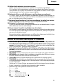
DOUBLE INSULATION FOR SAFER OPERATION
To ensure safer operation of this power tool, HITACHI has adopted a double insulation
design. “Double insulation” means that two physically separated insulation systems
have been used to insulate the electrically conductive materials connected to the
power supply from the outer frame handled by the operator. Therefore, either the
symbol “ ” or the words and “Double insulation” appear on the power tool or on
the nameplate.
Although this system has no external grounding, you must still follow the normal
electrical safety precautions given in this Instruction Manual, including not using
the power tool in wet environments.
To keep the double insulation system effective, follow these precautions:
䡬 Only HITACHI AUTHORIZED SERVICE CENTER should disassemble or assemble
this power tool, and only genuine HITACHI replacement parts should be installed.
䡬 Clean the exterior of the power tool only with a soft cloth moistened with soapy
water, and dry thoroughly.
Never use solvents, gasoline or thinners on plastic components; otherwise the
plastic may dissolve.
SAVE THESE INSTRUCTIONS
AND
MAKE THEM AVAILABLE TO
OTHER USERS OF THIS TOOL!

9
English
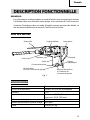
FUNCTIONAL DESCRIPTION
NOTE:
The information contained in this Instruction Manual is designed to assist you in
the safe operation and maintenance of the power tool.
Some illustrations in this Instruction Manual may show details or attachments
that differ from those on your own power tool.
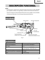
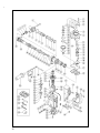
NAME OF PARTS
Fig. 1
Housing
Stopper
Switch Trigger
Side Handle
Handle
Nameplate
Tail Cover
Set Screw
(Under the Tail Cover)
Selector Lever
Brush Cap
(Inside the Tail Cover)
SPECIFICATIONS
Motor Single-Phase, Series Commutator Motor.
Power Source Single-Phase, 115 V 60 Hz
Current 8.7 A
Capacity Drill Bit: 1-9/16" (40 mm)
Core Bit: 4-1/8" (105 mm)
No-Load Speed 400/min
Full-load Blow 2800 bpm
Weight 14.8 lbs (6.7 kg)
Tool Holder

10
English
ASSEMBLY AND OPERATION
APPLICATIONS
Rotation and hammering function
䡬 Drilling anchor holes
䡬 Drilling holes in concrete
Hammering function only
䡬 Crushing concrete, chipping, digging, and squaring
(by applying optional accessories)
PRIOR TO OPERATION
1. Power source
Ensure that the power source to be utilized conforms to the power source
requirements specified on the product nameplate.
2. Power switch
Ensure that the switch is in the OFF position. If the plug is connected to a
receptacle while the switch is in the ON position, the power tool will start operating
immediately and can cause serious injury.
3. Extension cord
When the work area is far away from the power source, use an extension cord of
sufficient thickness and rated capacity (refer to page 9). The extension cord should
be kept as short as practicable.
WARNING: Damaged cord must be replaced or repaired.
4. Check the receptacle
If the receptacle only loosely accepts the plug, the receptacle must be repaired.
Contact a licensed electrician to make appropriate repairs.
If such a fautly receptacle is used, it may cause overheating, resulting in a serious
hazard.
5. Confirming condition of the environment:
Confirm that the work site is placed under appropriate conditions conforming to
prescribed precautions.
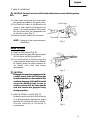
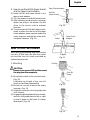
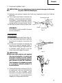
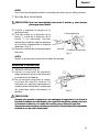
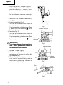
6. How to install dust cover (Fig. 2)
Always install the dust cover on the drill
bit or the taper shank adaptor. Insert the
dust cover until it lies flush in the
groove.
NOTE: For a thick drill bit, insert the
dust cover from drill rear.
Dust cover
Fig. 2
Insert up to the groove

11
English
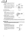
7. How to install tool
CAUTION: For tools such as a drill bit and a bull point, use only Hitachi genuine
parts.
(1) Clean, then smear the tool shank with
the grease provided in the green tube.
(2) Pull the tool holder in the direction of
arrow 1 and rotate it in the direction of
arrow 2 (counterclockwise). Fully insert
the tool shank into the hexagonal hole
of the front cover. (Fig. 3)
(3) Return the tool holder to fix the tool.
NOTE: Remove in the reverse order to
installation.
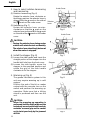
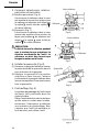
HOW TO USE
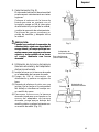
1. How to drill holes (Fig. 4)
(1) Pull the switch trigger after applying the
drill bit tip to the drilling position.
(2) It is unnecessary to forcibly press the
rotary hammer main body. It is sufficient
to slightly press the rotary hammer to
an extent that clips are freely
discharged.
CAUTION:
Although this machine is equipped with
a safety clutch, if the drill bit becomes
bound in concrete or other material, the
resultant stoppage of the drill bit could
cause the machine body to turn in
reaction. Ensure that the main handle
and side handle are gripped firmly
during operation.
2. How to chisel or crush (Fig. 5)
By applying the tool tip to the chiseling
or crushing position, operate the rotary
hammer by utilizing its empty weight.
Forcible pressing or thrusting is
unnecessary.
Front Cover
Tool Shank
Fig. 3
Tool Holder
Fig. 4
1
2
Fig. 5

12
English
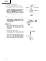
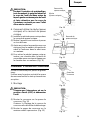
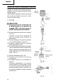
3. How to select rotation-hammering
and hammering.
(1) Rotation-hammering (Fig. 6)
Rotate the selector lever clockwise so
that the ▲ mark on the selector lever is
aligned with the ▲ mark on the side of
the mark on the under cover.
(2) Hammering (Fig. 7)
Rotate the selector lever counter-
clockwise so that the ▲ mark on the
selector lever is aligned with the ▲ mark
on the side of the mark on the under
cover.
CAUTION:
䡬 Turning the selector lever during motor
rotation will rotate the tool accidentally.
The selector lever should only be turned
when the motor is stopped.
4. Install the stopper (Fig. 8)
(1) Loosen the side handle and insert the
straight portion of the stopper into the
handle bolt hole from the front cover.
(2) Loosen the side handle, move the
stopper to the specified position and
rotate the grip of the side handle
clockwise to fix the stopper.
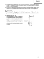
5. Warming up (Fig. 9)
The grease lubrication system in this
unit may require warming up in cold
regions.
Position the end of the bit so makes
contact with the concrete, turn on the
switch and perform the warming up
operation. Make sure that a hitting
sound is produced and then use the
unit.
CAUTION:
When the warming up operation is
performed, hold the side handle and the
main body securely with both hands to
maintain a secure grip and be careful
not to twist your body by the jammed
drill bit.
Fig. 6
Selector
Lever
Under Cover
▲
▲
Fig. 7
Selector
Lever
Under Cover
▲
▲
Fig. 8
Stopper
Side Handle
Fig. 9

13
English
6. How to use the drill bit (taper shank)
and the taper shank adaptor.
(1) Install drill bit with taper shank in the
taper shank adaptor.
(2) Turn the power on and drill a base hole.
(3) After cleaning out dust with a syringe,
attach the plug to the anchor tip and
drive in the anchor with a manual
hammer.
(4) To remove the drill bit with taper shank,
insert a cotter into the slot of the taper
shank adaptor, place supports under the
rotary hammer and tap the cotter with
a manual hammer. (Fig. 11)
HOW TO USE THE CORE BIT
When boring penetrating large hole use the
core bit. At that time use with the center
pin and the core bit shank provided as
optional accessories.
1. Mounting
CAUTION:
Be sure to turn power OFF and disconnect
the plug from the receptacle.
(1) Mount the core bit to the core bit shank.
(Fig. 12)
Lubricate the thread of the core bit
shank to facilitate disassembly.
(2) Mount the core bit shank to the rotary
hammer. (Fig. 13)
(3) Insert the center pin into the guide plate
until it stops.
(4) Engage the guide plate with the core bit,
and turn the guide plate to left or right
so that it does not fall even if it faces
downward. (Fig. 14)
Fig. 10
Drill Bit
(Taper shank)
Taper Shank Adaptor
Taper Shank
Adaptor
Cotter
Support
Fig. 11
Fig. 12
Core Bit
Core Bit
Shank
Fig. 13

14
English
2. How to bore (Fig. 15)
(1) Connect the plug to the receptacle.
(2) A spring is installed in the center pin.
Push it lightly to the wall or the floor
straight. Connect all over the surface of
the core bit tip and start operating.
(3) When boring about 3/16" (5 mm) in
depth the position of the hole will
establish. Bore after that removing the
center pin and the guide plate from core
bit.
(4) Application of excessive force will not
only expedite the work, but will
deteriorate the tip edge of the drill bit,
resulting in reduced service life of the
rotary hammer.
CAUTION:
When removing the center pin and the
guide plate, turn OFF the switch and
disconnect the plug from the
receptacle.
3. Dismounting (Fig. 16)
Remove the core bit shank from the
rotary hammer and strike the head of
the core bit shank strongly two or three
times with a manual hammer holding
the core bit, then the thread becomes
loose and the core bit can be removed.
Fig. 14
Center Pin
Core Bit
Core Bit Tip
Guide Plate
Fig. 15
Core Bit
Shank
Fig. 16

15
English
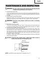
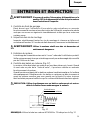
MAINTENANCE AND INSPECTION
WARNING: Be sure to switch power OFF and disconnect the plug from the
receptacle during maintenance and inspection.
1. Inspecting the drill bits
Since use of a dull tool will cause motor malfunctioning and degraded efficiency,
replace the drill bit with a new one or resharpening without delay when abrasion
is noted.
2. Inspecting the mounting screws
Regularly inspect all mounting screws and ensure that they are properly
tightened. Should any of the screws be loose, retighten them immediately.
WARNING: Using this rotary hammer with loosen screws is extremely
dangerous.
3. Maintenance of the motor
The motor unit winding is the very “heart” of the power tool. Exercise due care
to ensure the winding does not become damaged and/or wet with oil or water.
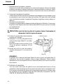
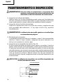
4. Inspecting the carbon brushes: (Fig. 17)
The motor employs carbon brushes which are consumable parts. When they
become worn to or near “wear limit”, it could result in motor trouble. When an
auto-stop carbon brush is equipped, the motor will stop automatically. At that
time, replace both carbon brushes with new ones which have the same carbon
brush Nos. shown in the figure.
In addition, always keep carbon brushes clean and ensure that they slide freely
within the brush holders.
CAUTION: Using this rotary hammer with a carbon brush which is worn in
excess of the wear limit will damage the motor.
NOTE: Use HITACHI carbon brush No.73 indicated in Fig. 17
Wear limit
No. of carbon brush
0.28" (7 mm)
0.67" (17 mm)
73
Fig. 17

16
English
䡬 Replacing carbon brushes:
(For parts name, refer to Fig. 1)
Loosen the two set screws and remove the tail cover. Remove the brush caps
and carbon brushes. After replacing the carbon brushes, tighten the brush caps
securely and to install the tail cover with securely tightening two set screws.
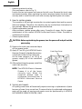
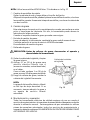
5. How to replase grease
This machine is full air-tight construction to protect against dust and to prevent
lubricant leakage. Therefore, the machine can be used without lubrication for
long periods. Replace the grease as described below.
䡬 Grease replacement period
After purchase, replace grease after every 6 months of usage. Ask for grease
replacement at the nearest HITACHI Authorized Service Center. Proceed for
replacement of grease.
䡬 Grease replenishment
CAUTION: Before replenishing the grease, turn the power off and pull out the
power plug.
(1) Remove the crank case cover and wipe
off the grease inside.
(2) Apply 0.7 oz (20 g) of HITACHI Electric
Hammer Grease A (standard accessory,
contained in tube) to the crank case.
As the tube contains 1 oz (30 g) of
grease, supply 2/3 of the contained
grease.
(3) After replenishing the grease, install the
crank case securely.
NOTE: The HITACHI Electric Hammer
Grease A is of the lower
viscosity type. When the
supplied grease tube is
consumed, purchase from a
HITACHI Autorized Service
Center.
6. Service and repairs
All quality power tools will eventually require servicing or replacement of parts
because of wear from normal use. To assure that only authorized replacement
parts will be used, all service and repairs must be performed by a HITACHI
AUTHORIZED SERVICE CENTER, ONLY.
Crank Case Cover
Fig. 18

17
English
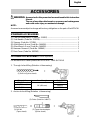
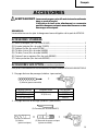
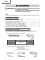
ACCESSORIES
WARNING: Accessories for this power tool are mentioned in this Instruction
Manual.
The use of any other attachment or accessory can be dangerous
and could cause injury or mechanical damage.
NOTE:
Accessories are subject to change without any obligation on the part of the HITACHI.
STANDARD ACCESSORIES
(1) Case (Molded plastic) (Code No. 313097)............................................................. 1
(2) Side Handle (Code No. 313078)............................................................................. 1
(3) Stopper (Code No. 971786).................................................................................... 1
(4) Allen Wrench 4 mm (Code No. 944458)................................................................1
(5) Allen Wrench 5 mm (Code No. 944459)................................................................1
(6) Hammer Grease A (Code No. 981840) .................................................................. 1
(7) Dust Cover (Code No. 993245) .............................................................................. 1
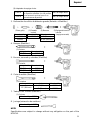
OPTIONAL ACCESSORIES.....sold separately
For accessories in detail please call HITACHI AT 1-800-59-TOOLS
1. Through-hole drilling (Rotation + Hammering)
2. Anchor hole drilling (Rotation + Hammering)
Overall length
16" (400 mm)
Code No.
985374
985375
985376
External dia.
1/2" (12.7 mm)
1" (25.4 mm)
1-1/2" (38.1 mm)
(1) Drill bit
(Taper shank)
(3) Cotter (Code No. 944477)
(2) Taper shank adaptor
(Spline shank)
(1) Drill bit (Spline shank)

18
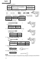
English
(2) Taper shank adaptor
3. Large-dia. hole boring (Rotation + Hammering)
4. Crushing (Hammering)
5. Groove digging and edging (Hammering)
6. Asphalt cutting (Hammering)
7. Digging
8. Syringe (for chip removal)
NOTE:
Specifications are subject to change without any obligation on the part of the HITACHI.
(Guide plate)
Code No.
985388
955169
(2) Core bit
External dia.
2" (50 mm)
4-1/8" (105 mm)
(1) Center pin
Code No.
955165
(3) Core bit shank
(Spline shank)
Taper shank adaptor formed
A-taper or B-taper is provided as
optional accessory, but drill bit for
it is not provided
Code No. 985377
Code No. 985378
A-taper
B-taper
(1) Bull point
Overall length Code No.
12" (300 mm) 985383
(1) Cold chisel
Overall length Code No.
12" (300 mm) 985381
18" (460 mm) 985382
(1) Cutter
Overall length Width Code No.
12" (300 mm)
1-1/2" (38 mm) 985384
2" (50 mm) 985385
(1) Scoop
Code No. 985386
Code No. 944575

19
Français
INFORMATIONS IMPORTANTES
Lire et comprendre toutes les instructions de fonctionnement, les précautions de
sécurité et les avertissements dans ce mode d’emploi avant d’utiliser ou d’entretenir
cet outil motorisé.
La plupart des accidents causés lors de l’utilisation ou de l’entretien de l’outil motorisé
proviennent d’un non respect des règles ou précautions de base de sécurité. Un
accident peut la plupart du temps être évité si l’on reconnaît une situation de danger
potentiel avant qu’elle ne se produise, et en observant les procédures de sécurité
appropriées.
Les précautions de base de sécurité sont mises en évidence dans la section
“SECURITE” de ce mode d’emploi et dans les sections qui contiennent les
instructions de fonctionnement et d’entretien.
Les dangers qui doivent être évités pour prévenir des blessures corporelles ou un
endommagement de la machine sont identifiés par AVERTISSEMENTS sur l’outil
motorisé et dans ce mode d’emploi.
Ne jamais utiliser cet outil motorisé d’une manière qui n’est pas spécifiquement
recommandée par HITACHI sans avoir d’abord vérifié que l’utilisation prévue est
sans danger pour vous et les autres.
SIGNIFICATION DES MOTS D’AVERTISSEMENT
AVERTISSEMENT indique des situations potentiellement dangereuses qui, si elles
sont ignorées, pourraient entraîner de sérieuses blessures personnelles.
PRECAUTION indique des situations dangereuses qui, si elles sont ignorées, pourrait
entraîner de légères blessures personnelles ou endommager la machine.
REMARQUE met en relief des informations essentielles.

20
Français
SECURITE
REGLES GENERALE DE SECURITE
AVERTISSEMENT: Lire et coxmprendre toutes les instructions.
Un non respect de toutes les instructions ci-dessous peut
entraîner une électrocution, un incendie et/ou de
sérieuses blessures personnelles.
CONSERVER CES INSTRUCTIONS
1. Zone de travail
(1) Garder la zone de travail propre et bien éclairée. Les établis mal rangés et les
zones sombres invitent aux accidents.
(2) Ne pas utiliser les outils motorisés dans une atmosphère explosive, telle
qu’en présence de liquides inflammables, de gaz ou de poussières. Les outils
motorisés créent des étincelles qui risquent d’enflammer la poussière ou les
vapeurs.
(3) Tenir les spectateurs, les enfants et les visiteurs éloignés, lors de l’utilisation
de l’outil motorisé. Une distraction peut faire perdre le contrôle de la machine.
2. Sécurité électrique
(1) Les outils à double isolation sont équipés d’une fiche polarisée (une lame
est plus large que l’autre). Cette fiche ne pénétrera dans une prise secteur
polarisée que dans un sens. Si la fiche ne rentre pas complètement dans la
prise, la retourner. Si elle ne rentre toujours pas, contacter un électricien
qualifié pour installer une prise polarisée. Ne pas modifier la fiche d’aucune
façon. La double isolation élimine le besoin d’un cordon d’alimentation à
trois fils et d’un système d’alimentation avec mises à la terre.
(2) Eviter tout contact corporel avec les surfaces mises à la terre telles que les
canalisations, les radiateurs, les réchauds et les réfrigérateurs. Il y a un risque
accru d’électrocution si son corps est mis à la terre.
(3) Ne pas exposer les outils motorisés à la pluie ou à l’humidité. De l’eau
pénétrant à l’intérieur de l’outil motorisé augmente le risque d’électrocution.
(4) Ne pas maltraiter le cordon d’alimentation. Ne jamais utiliser le cordon pour
porter les outils ou tirer sur la fiche du réceptacle. Garder le cordon à l’écart
de la chaleur, de l’huile, des arêtes coupantes ou des pièces en mouvement.
Remplacer les cordons endommagés immédiatement. Des cordons
endommagés augmentent le risque d’électrocution.
(5) Lors de l’utilisation d’un outil motorisé, utiliser un cordon de rallonge
extérieur marqué “W-A” ou “W”. Ces cordons sont prévus pour une utilisation
extérieure et réduisent les risques d’électrocution.
3. Sécurité personnelle
(1) Rester sur ses gardes, regarder ce que l’on fait et utiliser son sens commun
lors de l’utilisation d’un outil motorisé. Ne pas utiliser un outil en état de
fatigue ou sous l’influence de drogues, d’alcool ou de médicaments. Un
moment d’inattention lors de l’utilisation de l’outil motorisé peut entraîner
de sérieuses blessures personnelles.
Page is loading ...
Page is loading ...
Page is loading ...
Page is loading ...
Page is loading ...
Page is loading ...
Page is loading ...
Page is loading ...
Page is loading ...
Page is loading ...
Page is loading ...
Page is loading ...
Page is loading ...
Page is loading ...
Page is loading ...
Page is loading ...
Page is loading ...
Page is loading ...
Page is loading ...
Page is loading ...
Page is loading ...
Page is loading ...
Page is loading ...
Page is loading ...
Page is loading ...
Page is loading ...
Page is loading ...
Page is loading ...
Page is loading ...
Page is loading ...
Page is loading ...
Page is loading ...
Page is loading ...
Page is loading ...
Page is loading ...
Page is loading ...
-
 1
1
-
 2
2
-
 3
3
-
 4
4
-
 5
5
-
 6
6
-
 7
7
-
 8
8
-
 9
9
-
 10
10
-
 11
11
-
 12
12
-
 13
13
-
 14
14
-
 15
15
-
 16
16
-
 17
17
-
 18
18
-
 19
19
-
 20
20
-
 21
21
-
 22
22
-
 23
23
-
 24
24
-
 25
25
-
 26
26
-
 27
27
-
 28
28
-
 29
29
-
 30
30
-
 31
31
-
 32
32
-
 33
33
-
 34
34
-
 35
35
-
 36
36
-
 37
37
-
 38
38
-
 39
39
-
 40
40
-
 41
41
-
 42
42
-
 43
43
-
 44
44
-
 45
45
-
 46
46
-
 47
47
-
 48
48
-
 49
49
-
 50
50
-
 51
51
-
 52
52
-
 53
53
-
 54
54
-
 55
55
-
 56
56


Hitachi DH 40FA Instruction And Safety Manual
- Category
- Power tools
- Type
- Instruction And Safety Manual
Ask a question and I''ll find the answer in the document
Finding information in a document is now easier with AI
in other languages
- français: Hitachi DH 40FA
- español: Hitachi DH 40FA
Related papers
-
Hitachi DH40FB User manual
-
Hitachi DH 38YE2 User manual
-
-
-
-
-
-
-
-