Magnum Cenik 6.6 Use And Installation Manual

Category
Pellet stove
Type
Use And Installation Manual
MAGNUM Original Sauna Stove
6.6 kW 9.0 kW 10.5 kW
MAGNUM Cenik and Lite
Sauna Stove
6.6 kW 9.0 kW 10.5 kW
Magnum Ruutu L and C
6.6kW - 9.0kW 10.5kW
Use and Installation
With Finlandia and Magnum RC
Control Centers
Use and installation manual for a MAGNUM sauna stove 16.06.2015 2
Starsauna Oy Technical support:
Pistotie 4 info@magnumkiuas.fi
15860 Hollola, Finland
Table of contents:
Safety instructions: 3
1 Using the device - Finlandia Control Center ...................................................... 4
1.1 Control functions - Finlandia Control Center ..................................................... 4
1.2 Control functions - Magnum RC Control Center ............................................... 5
1.3 Menu structure - Finlandia Control Center......................................................... 6
1.4 Menu structure - Magnum RC Control Center ................................................... 6
2 Using the sauna stove........................................................................................... 7
2.1 Adjustable settings ............................................................................................... 7
2.2 Target temperature ............................................................................................... 7
2.3 Heating time ......................................................................................................... 7
2.4 Timer ..................................................................................................................... 8
2.5 Turning the sauna on ............................................................................................ 8
2.6 Directions for using the sauna ............................................................................. 9
3 Installation of the sauna stove ........................................................................... 10
3.1 Installation: ......................................................................................................... 11
3.2 Installing the thermostat sensor ......................................................................... 13
3.3 Control panel installation ................................................................................... 14
3.4 Installing the control centers in the sauna room ............................................... 15
4 Installation images ............................................................................................. 16
4.1 Thermostat and Controller ................................................................................. 16
4.2 Ventilation in the sauna room............................................................................ 17
4.3 Piling the stones in the sauna stove ................................................................... 18
4.4 Images showing the sauna stove ....................................................................... 19
4.5 The sauna stove's wall condector ...................................................................... 20
5 Technical information and safety distances of the sauna stoves ..................... 21
5.1 Technical information ........................................................................................ 21
5.2 Safety distances .................................................................................................. 22
6 Warranty ............................................................................................................. 23
7 Connection diagram ........................................................................................... 24
8 Problems / troubleshooting ................................................................................ 25
Use and installation manual for a MAGNUM sauna stove 16.06.2015 3
Starsauna Oy Technical support:
Pistotie 4 info@magnumkiuas.fi
15860 Hollola, Finland
Safety instructions:
Read these instructions carefully before
installing and using the sauna stove.
These instructions are intended for the use of
the owner of the sauna and the electrician who
installs the sauna stove. The owner of the sauna
receives the instructions for setting up and
using the sauna stove after the stove has been
installed.
Malfunctions caused by errors in installation or
use are not covered by the warranty. THIS
INCLUDES ERRORS IN THE PILING OF
ROCKS!
Do not open the cover of the sauna stove’s
junction box while the stove is on.
Before beginning the installation process, verify
that the device is de-energized (has been
disconnected from the power supply).
Furthermore, ensure that the device has been
grounded properly.
Do not touch the components or microcircuits
inside the device, as the electrostatic discharge
could damage the device.
Use and installation manual for a MAGNUM sauna stove 16.06.2015 4
Starsauna Oy Technical support:
Pistotie 4 info@magnumkiuas.fi
15860 Hollola, Finland
I.Using the device - Finlandia Control Center
Section I.1 Control functions - Finlandia
Control Center
Sauna stove On/Off
Menu
Decrease
Increase
Lights button
The heating/timing indicator light
Sauna stove light’s indicator light
Menu settings indicator light
Number display
Legend for the parts of the control panel:
1.
On/off button. Pressing this button turns the sauna stove on and off. If the timer has been
set, pressing this button starts the timer for heating the sauna.
Tip: Pressing this button for a longer duration overrides the timer and starts the heating
of the sauna immediately.
2.
Menu button. By pressing this you can move through the menus of the device as follows:
(Default mode > Target temperature > Heating time > Timer > Default mode)
3.
(˅) button. This button is used to decrease the default values.
4.
(˄) button. This button is used to increase the default values.
5.
Lights button. By pressing this, you can turn on the sauna stove’s light. Pressing it again
turns the light off. (Only used in models with lights or a separate fiber kit)
6.
"Device on" light. This light is constantly on while the sauna stove is on.
The light "glows" when the timer is in use. The light is turned off when the sauna stove is not
on.
7.
Sauna stove light’s indicator light. This light is on as an indicator of the fiber light kit of the
sauna stove / sauna being on.
8.
Menu settings indicator light. This light comes on when a menu setting is adjusted (timer,
time the device is on, target temperature of the sauna stove)
9.
Three-digit display
Use and installation manual for a MAGNUM sauna stove 16.06.2015 5
Starsauna Oy Technical support:
Pistotie 4 info@magnumkiuas.fi
15860 Hollola, Finland
1.2 Control functions - Magnum RC Control Center
Sauna stove On/Off
Menu
Decrease
Increase
Lights button
The signal light of heating/timing
Signal light of the stove light
Signal light of the menu settings
Number display
Legend for the parts of the control panel:
1.
On/off button. Pressing this button turns the sauna stove on and off. If the timer has been
set, pressing this button starts the timer for heating the sauna. Tip: Pressing this button for a
longer duration overrides the timer and starts the heating of the sauna immediately.
2.
Menu button. By pressing this you can move through the menus of the device as follows:
(Default mode > Target temperature > Heating time > Timer > Default mode)
3.
() button. This button is used to decrease the default values.
4.
(+) button. This button is used to increase the default values.
5.
Lights button. By pressing this, you can turn on the sauna stove’s light. Pressing it again turns
the light off. (Used only in models with lights)
6.
Timer light. Light is on: heating time setting / timer setting mode (or the default mode, if the
display shows the remaining time).
7.
Target temperature setting indicator light. When this light is on, it is possible to change the
target temperature.
8.
"Device on" light. This light is constantly on when the sauna stove is on.
The light "glows" when the timer is in use. The light is turned off when the sauna stove is not
on.
9.
Three-digit display
Use and installation manual for a MAGNUM sauna stove 16.06.2015 6
Starsauna Oy Technical support:
Pistotie 4 info@magnumkiuas.fi
15860 Hollola, Finland
1.3 Menu structure - Finlandia Control Center
Default status Target temperature Heating time Timer
The adjustment menus of the device are shown in the image above. The user can
move from one menu to another using the Menu button. When the sauna stove is
on, the (˄) and (˅) buttons may be used to move to the mode where you can adjust
the settings in the order shown in the image above.
1.4 Menu structure - Magnum RC Control Center
Default status Target temperature Heating time Timer
The adjustment menus of the device are shown in the above image. The user can
move from one menu to another using the Menu button. When the sauna stove is
on, the (+) and () buttons may be used to move to the mode where you can adjust
the settings in the order shown in the image above.
Use and installation manual for a MAGNUM sauna stove 16.06.2015 7
Starsauna Oy Technical support:
Pistotie 4 info@magnumkiuas.fi
15860 Hollola, Finland
II.Using the sauna stove
Section II.1 Adjustable settings
Section II.2 Target temperature
The sauna's target temperature may be adjusted in steps of one Celsius. The
minimum temperature is 40 degrees and the maximum temperature is 110 degrees.
This setting is saved.
The target temperature may be adjusted in two different ways.
1. The Menu button shows the target temperature on the screen.
You may use the +/˄ and /˅ buttons to change the value. If you do
not press any buttons, the controller will stop displaying the target
temperature menu automatically in approximately 10 seconds. You
may also leave the menu by pressing the Menu button repeatedly.
2. When the sauna temperature is on the display, pressing the (+/˄) or
(/˅) button causes the controller to move directly to setting the
target temperature. Leaving this menu is done as in section 1.
Section II.3 Heating time
You may set the sauna stove's heating time to be between 1 h and 6 h. The
adjustment takes place in steps of 0.5 h.
This value needs to be set when the device is turned off.
You may move to this setting from the default mode by pressing the Menu button
twice.
It is possible to reduce the time the stove is on when the sauna is heating.
You may increase or decrease the time of the sauna session by pressing the (+/˄) or
(/˅) button when the remaining time is on the display. In this case, the adjustment
step is 15 minutes. This setting is not saved to the memory. You can go back to the
default mode by pressing the Menu button twice.
Parameter
Adjustment
step
Default
value
Note!
Target
temperature
1 °C
60 °C
Heating time
30 min
1 h
see section 2.3
Timer time
30 min
0 h
(not in use)
Use and installation manual for a MAGNUM sauna stove 16.06.2015 8
Starsauna Oy Technical support:
Pistotie 4 info@magnumkiuas.fi
15860 Hollola, Finland
Section II.4 Timer
You can move from the default mode to the timer by pressing the Menu button
three times in a row. The (+/˄) and (/˅) buttons are used to change the timer’s
setting. The adjustment range is 0.5 h 24 h and the adjustment step is 0.5 h. When
this value is zero, the timer is not in use.
This setting may only be changed when the device is off.
Section II.5 Turning the sauna on
Turn the sauna stove’s power on using the control switch at the lower part of the
sauna stove. Pressing the controller's On/Off button makes the sauna stove start
heating the sauna until the target temperature has been reached. The stove’s
indicator light in the controller will be turned on. The decimal mark lights up on the
lower right side of the screen as a signal of the resistors being on.
(If the timer has been set, the On/Off button turns the timer on and the sauna stove
begins heating only after the timer has run out). The On/Off button turns the sauna
stove off.
Control switch
Tip: If the timer has been set but the sauna stove is not on, you may override the
timer by pressing the On/Off button and keeping it pressed for a couple of seconds.
This causes the stove to start heating the sauna immediately. The timer’s setting
remains in the memory.
Magnum RC Finlandia
Basic setting Time left Default setting Time left
When the machine is on, the default mode and the remaining time alternate on the
screen with an interval of approximately 10 seconds.
Use and installation manual for a MAGNUM sauna stove 16.06.2015 9
Starsauna Oy Technical support:
Pistotie 4 info@magnumkiuas.fi
15860 Hollola, Finland
Section II.6 Directions for using the sauna
Heat the sauna stove once before taking it into use, as the protective
substances in the new stones may give off odors while the sauna stove is
heating. Ensure sufficient ventilation.
The recommended temperature is 55-70 degrees.
The sauna stove heats to a proper sauna temperature in approximately 25
50 minutes, depending on the size of the sauna stove, the size of the sauna
and the ventilation.
Use water that is suitable for domestic use when throwing water on the
stove for heating the sauna.
Do not throw water on the stove if there are people next to it, as the water
splashing from the sauna stove and the steam it creates are burning hot.
Move carefully in the sauna, as the floors may be slippery.
Quality requirements for the heating water
Water condition:
Effect:
Recommendation:
Water containing humus
Color, taste, deposits
<12 mg/l
Water containing iron
Color, odor, taste, deposits
<0.2 mg/l
Hardness: the most important
substances are manganese
(Mn) and chalk or calcium
(Ca)
Deposits
Mn: <0.05 mg/l
Ca: <100 mg/l
Water containing chloride
Health risk
Use is banned
Seawater
Fast corrosion
Use is banned
RC Installation Template, cut out from here.
-----------------------------------------------------------------------------------------------------------------------
Use and installation manual for a MAGNUM sauna stove 16.06.2015 10
Starsauna Oy Technical support:
Pistotie 4 info@magnumkiuas.fi
15860 Hollola, Finland
III.Installation of the sauna stove
The electrical installation may only be performed by a qualified
electrician.
Instructions for electrical installation are provided in the circuit
diagram in these installation directions and on a sticker in the
sauna stove.
The electrical installation work may only be performed by an
electrician qualified for the job in accordance with applicable
regulations.
The sauna stove is connected to the power grid semi-permanently with
H07RN-F or similar rubber cable.
Check the required cable dimensions in the table below.
Note: the use of a PVC cable as a connection cable is not allowed.
The power switch in the device is a so-called control switch and does not
fully de-energize the sauna stove.
Table
Sauna stove
POWER
FUSE
FEED CABLE
SIZE OF THE
SAUNA
Magnum 6.6
6.6 KW
3x10 A
5x1.5 mm2
5-9 m3
Magnum 9
9 KW
3x16 A
5x2.5 mm2
8-15 m3
Magnum 10.5
10.5 KW
3x16 A
5x2.5 mm2
10-20 m3
Use and installation manual for a MAGNUM sauna stove 16.06.2015 11
Starsauna Oy Technical support:
Pistotie 4 info@magnumkiuas.fi
15860 Hollola, Finland
Section III.1 Installation:
1. Remove the stainless steel frame from the upper part of the sauna stove.
2. Remove the protective plastics.
3. Set the sauna stove's lower part in the location you have chosen for the stove in a
way that ensures that the maintenance/installation hatch at the foot of the sauna
stove faces an open space. In the Lite / Cenik model, turn the sauna stove on its
side, against a clean platform. Make sure the sauna stove is not scratched.
4. Open the hatch at the base of the sauna stove and connect the feeder line to the
sections of the bayonet joint. L1, L2, L3, N, Ground, Ground (see image)
5. Temperature reduction (Connector J5) (If this feature is in use, it is possible to
connect a relay or contactor coil to the output, which control the heating of the
building) Detach the connector from the circuit card and screw the cables to the
connector. Then, press the connector back onto the circuit card. The screws will
point right when pressing the connector.
N - 230VAC OUT - Blue above
P - External - Brown below.
Use and installation manual for a MAGNUM sauna stove 16.06.2015 12
Starsauna Oy Technical support:
Pistotie 4 info@magnumkiuas.fi
15860 Hollola, Finland
6. Connect the thermostat sensor according to Section 3.2.
7. Connect the control panel according to Section 3.3.
8. Close the hatch at the lower part of the sauna stove.
9. Connect the other end of the feed cable to the outlet. (Note: the upper edge of the
outlet should be at most 400 cm from the floor)
10. Test the functioning of the resistors by turning the sauna stove on. If all the
resistors do not heat or there is some other problem, contact the retailer or the
manufacturer.
11. Install the lower part of the sauna stove vertically using the adjustment feet.
12. Pile the stones in the lower part of the sauna stove. (Leave 4-5 cm of free space for
the upper edge in order to install the upper part of the sauna stove.) Do not wedge
the resistors. Ensure that the resistors travel vertically where they have been
attached to the bottom plate throughout the entire section where the stones have
been installed.
13. Install the stainless steel frame of the upper part of the sauna stove. Chapter 4.3,
image 3
14. Pile the stones in the upper part of the sauna stove in a way that ensures that no
resistors are visible. Cover the resistors entirely with stones. Place stones that
cannot fall to the benches or to the floor from between the vertical profiles in the
outer edge. (NOTE: a freely glowing resistor may cause an combustion hazard
even outside the protective distance.) Chapter 4.3 Piling the stones on the sauna
stove
15. Use stones with a diameter of 5-10 cm, such as olivine diabase, olivine or
peridotite, for the sauna stove.
16. The use of ceramic stones other than (KERKES) is forbidden. Other ceramic
stones may cause the resistors to break down prematurely.
17. The stones of the sauna stove need to be installed again, the stone area of the sauna
stove cleaned and the broken stones replaced with new ones once a year. We
recommend that you change the stones every 2 years, depending on use.
18. The sauna stove’s stones decrease in size due to the stainless steel frame's thermal
expansion and the weathering of stones while in use, so ensure that no resistors
become visible. Add stones when necessary.
Use and installation manual for a MAGNUM sauna stove 16.06.2015 13
Starsauna Oy Technical support:
Pistotie 4 info@magnumkiuas.fi
15860 Hollola, Finland
Section III.2 Installing the thermostat sensor
Heat sensor Connection of the LIYY wire
Connecting the sensor wire from the left LIYY CABLE (gray):
To
connector
Brown
White
Green
Yellow
To circuit
card
1
2
3
4
Connection of the sensor wire, from the left SILICONE
CABLE (light brown, right on the picture):
To
connector
Blue
White
Red
Yellow
To circuit
card
1
2
3
4
All Magnum sauna stoves bought from 1 October 2015 onwards have been equipped
with the new silicone cable.
Connect the connector to the circuit card’s connector and press it carefully all the
way down.
When installing the thermostat sensor on the wall, the distance from the roof to the
upper edge of the sensor should be 100 mm. The sensor must be located 500-1000
mm from the upper edge of the sauna stove.
Furthermore, the sensor must be located at least 1000 mm from a non-directed incoming
air valve or 500 mm from an incoming air valve which is located away from the device.
See the image at page 16.
Install the thermostat cable behind the panel in the air
vent. If this is not possible, use an installation baseboard.
Make sure that the incoming air does not disturb the heat
sensor.
Do NOT cut the wire from the thermostat’s side. The
thermostat sensor does not function if the wires are
continued/reconnected. If the wire needs to be shortened,
shorten it from the connector's side. In other cases,
contact the technical support.
Use and installation manual for a MAGNUM sauna stove 16.06.2015 14
Starsauna Oy Technical support:
Pistotie 4 info@magnumkiuas.fi
15860 Hollola, Finland
Section III.3 Control panel installation
Controller's connector Counterpart to the controller's connector
on the circuit card on the right
Connect the control panel's connector as shown in the attached diagram. Attach the
connector in the wire to the circuit card and press it carefully all the way down. The
process of connecting the connector card to the sauna stove is the same for the Finlandia
and Magnum RC models.
Connecting the Finlandia controller card
Connecting from the left
The Control panel can be installed inside the sauna. Inside the sauna, the control
panel should be installed in a way that ensures that the distance from the sauna
stove is at least 500 mm and the distance to the upper edge of the panel is at least
1000 mm. This is shown in the image on page 16.
Connector
Color
On circuit card
number:
1.
Brown
NTC
2.
Gray
GND
3.
Pink
+5V
4.
White
RELAY
5.
Green
TR1
6.
Yellow
EXT
7.
Blue
TR2
8.
Red
LIGHT
approx.
Legend
Color
8
+5V
Pink
7
GND
Gray
6
LIGHT
Red
5
TR2
Blue
4
TR1
Green
3
RELAY
White
2
TEMP
Brown
1
EXT
Yellow
Use and installation manual for a MAGNUM sauna stove 16.06.2015 15
Starsauna Oy Technical support:
Pistotie 4 info@magnumkiuas.fi
15860 Hollola, Finland
3.4 Installing the control centers in the Sauna room
Finlandia
1. Check the central unit’s height and distance in the installation manual. Chapter 4.1
2. Use a box drill to drill a 70 mm hole in the panel for the box. Be careful not to drill all the
way to the insulation! If you penetrate the insulation plate/foil, repair it with aluminum tape.
3. Install the bottom of the box to the hole. Fasten it with fasteners that come with the bottom.
4. Draw the wires from the sauna stove to the hole along the lower edge of the panel, for
example, and pull them out of the box.
5. Install the central unit's bracket in the box.
6. Connect the wires. See Chapter 3.3
7. Press the central unit into the bracket and attach it with two plastic tacks.
8. Install the controller to the sauna stove as set in Chapter 3.3.
NOTE! The electric grid connection process may only be performed by a licensed electrician.
The bottom of the box is not delivered with the sauna stove. One suitable
box is the ABB mounting box for board walls AUS-15.2p. These boxes are
sold in all well-equipped hardware stores.
Magnum RC
1. Install the screws in the panel using the template supplied with the
panel. Leave the screws approximately 2 mm out of the wooden
surface. Cut the template from the side 9.
2. If you want the wire to go through the panel, drill a hole in the
template part. Diameter of the hole must be at least 8 mm.
3. After screwing in the screws and drilling the hole, take the wire of
the controller through the hole and install the controller on the
screws. Finally, remove the protective liner from the controller.
4. Connect the controller to the sauna stove as provided in Chapter
3.3.
Do NOT cut the wire from the side of the controller. The controller does
not function if the wires are extended/reconnected. If the wire needs to be
shortened, shorten it from the connector's side. In other cases, contact the
technical support.
Use and installation manual for a MAGNUM sauna stove 16.06.2015 16
Starsauna Oy Technical support:
Pistotie 4 info@magnumkiuas.fi
15860 Hollola, Finland
4 Installation images
4.1 Thermostat and Controller
A. The minimum distance of the thermostat from the upper edge of the sauna stove is 500-1000
mm. PAY ATTENTION TO THE INCOMING AIR VALVE. If incoming air cannot be
directed away from the thermostat, the valve may not be installed less than 1000 mm from
the incoming air valve. If it can, the installation distance may be between 500 mm - 1000
mm.
B. The distance of the thermostat from the roof is 100 mm.
C. The minimum distance of the control panel from the sauna stove is 500 mm.
D. The maximum height of the control panel from the floor is 1000 mm.
Use and installation manual for a MAGNUM sauna stove 16.06.2015 17
Starsauna Oy Technical support:
Pistotie 4 info@magnumkiuas.fi
15860 Hollola, Finland
4.2 Ventilation in the sauna room
Power ventilation for the sauna and the electric stove
1. Incoming air
2. Outgoing air
Use and installation manual for a MAGNUM sauna stove 16.06.2015 18
Starsauna Oy Technical support:
Pistotie 4 info@magnumkiuas.fi
15860 Hollola, Finland
4.3 Piling stones in the sauna stove
Preparations
1. Ensure that the control panel, the temperature sensor, any floor heating reduction and the sauna
stove have been correctly connected to the power supply
by an electrician.
2. The benches should be installed before the stones are
piled in the sauna stove, IF the sauna stove is integrated
through the benches. It will be difficult to move the sauna
stove after the stones have been piled it. Place the sauna
stove in its intended location, considering the safety
distances.
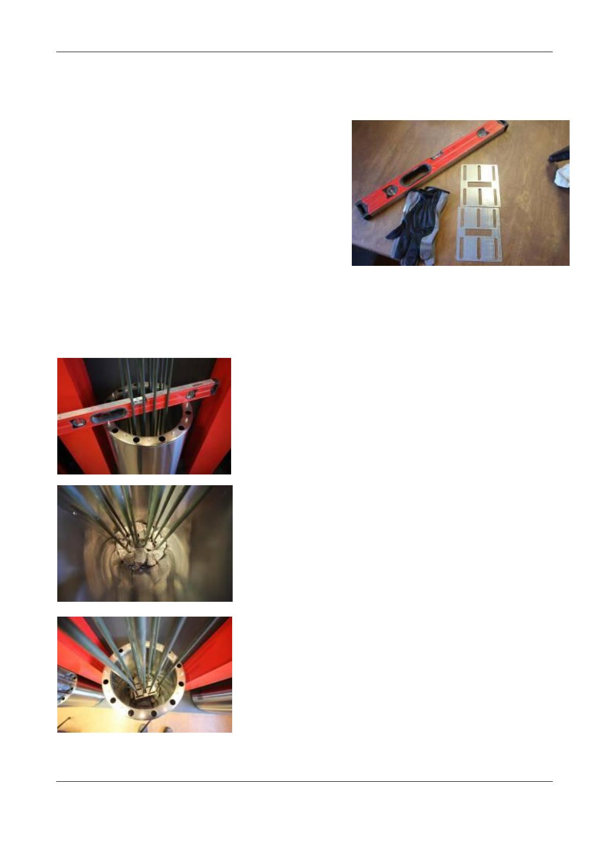
3. For piling stones in the sauna stove, you will need a
spirit level, protective gloves, 80 110 kg of washed rocks with a diameter of 5 10 cm, depending
on the sauna stove model (check the correct amount from the manual), and the resistors that were
included in the sauna stove delivery.
Piling stones
1. Straighten the sauna stove with the help of a spirit level. The
spirit level can be lowered between the resistors to the lower
level of the sauna stove, where you can check the straightness.
Check the straightness in both directions, adjust with the
adjustment feet. If no stones have been piled into the sauna
stove yet, the adjustment feet can be rotated by hand, but they
can also be adjusted with a 17 mm ring spanner.
2. Pile the stones into the lower part of the sauna stoves. Do
not wedge the resistors. Ensure that the resistors travel
vertically where they have been attached to the bottom plate,
throughout the entire section where the stones have been
installed. Stop piling stones when you reach the end of the
middle part of the resistor, and move to Section 3.
ENSURE throughout the entire stone piling process that
there are stones between the resistors, and that the
resistors cannot come in contact with each other! If the
stones have been piled incorrectly, the resistors can melt
into each other, which is not covered by the warranty!
3. Lower the resistor plate onto the stones as shown on the
images, and continue piling the stones. It is very important to
pile stones properly between the resistors, and for the resistors
to be aligned straight. This ensures that the resistors cannot
bend against each other, which might otherwise cause the
resistors to break. However, do not put too many stones
between the resistors.
Use and installation manual for a MAGNUM sauna stove 16.06.2015 19
Starsauna Oy Technical support:
Pistotie 4 info@magnumkiuas.fi
15860 Hollola, Finland
4. Stop piling the stones when you have reached a level of approx. 5 10 cm from the upper section of the
lower part. The upper part is installed inside the lower section.
5. Lift the upper part in its place. Position the upper part so that the spaces between the profiles of the upper
part would be aligned with the big holes in the lower part (the middle image). The other resistor plate can be
used as a gauge throughout the entire piling process to ensure that the resistors are aligned straight. For the
outer edge of the upper part, you must select stones that cannot fall through the vertical profiles. Choose
smooth stones for this to ensure a visually pleasing outcome. Also pile stones between the resistors, so that
the resistors cannot become in contact with each other.
6. Pile the upper part with stones until you have reached approx. 5 10 cm from the top of the resistors.
Lower the upper resistor plate in its place, and finish piling stones in the sauna stove. Ensure that there are
enough stones on top. It is recommended to choose big stones for the top of the sauna stove, so that they
cannot fall through the vertical profiles.
7. The sauna stove has now been piled with stones. The sauna stove must be heated once before people use it
for the first time, and the sauna must be thoroughly ventilated. There may be impurities in the stones, and
there may be some residue of storage/machining lubricants which will disappear during the first heating.
When you are using the sauna, monitor the settling of the stones, and add more stones on top, if necessary.
Other remarks:
If necessary, attach the sauna stove to walls using the mounting brackets included in the delivery.
A sauna stove with too few stones is a fire hazard!
Covering the sauna stove is a fire hazard!
The uppermost layer of the stones must be as tight as possible, the resistors must not be visible.
It is recommended that the sauna stove stones are piled again on a yearly basis! Always replace
burned and cracked stones with new ones. If you use the sauna every day, it is recommended that the
stones are piled again every 3 mths.
The use of ceramic stones other than (KERKES) is forbidden. Other ceramic stones may cause the
resistors to break down prematurely.
Use and installation manual for a MAGNUM sauna stove 16.06.2015 20
Starsauna Oy Technical support:
Pistotie 4 info@magnumkiuas.fi
15860 Hollola, Finland
4.5 Sauna stove wall bracket
1. Fit the brackets to the sauna stove/wall before attaching to the wall. In Lite/Original/Cenik
sauna stoves, the bracket can be installed to the outer edge or between the vertical profile;
in Ruutu sauna stoves, anywhere between the squares.
2. Bend the brackets, if necessary. PLEASE NOTE: if you are bending the brackets by hand,
use protective gloves.
3. When the bracket seems to be positioned well, mark the attachment points on the wall.
4. Drill a small starting hole at the mark, so that the panel would not crack during the screwing
process.
5. Place the brackets to the hollows of the upper part of the sauna stove, according to the
image, and screw the brackets to the wall.
6. Finish piling the sauna stove with stones. The brackets will be covered by the stones.
  • Page 1 1
  • Page 2 2
  • Page 3 3
  • Page 4 4
  • Page 5 5
  • Page 6 6
  • Page 7 7
  • Page 8 8
  • Page 9 9
  • Page 10 10
  • Page 11 11
  • Page 12 12
  • Page 13 13
  • Page 14 14
  • Page 15 15
  • Page 16 16
  • Page 17 17
  • Page 18 18
  • Page 19 19
  • Page 20 20
  • Page 21 21
  • Page 22 22
  • Page 23 23
  • Page 24 24
  • Page 25 25
  • Page 26 26
  • Page 27 27

Magnum Cenik 6.6 Use And Installation Manual

Category
Pellet stove
Type
Use And Installation Manual

Ask a question and I''ll find the answer in the document

Finding information in a document is now easier with AI