Chroma 63800 Series Operation & Programming Manual
- Category
- Measuring, testing & control
- Type
- Operation & Programming Manual


Programmable AC/DC Electronic Load
63800 Series
Operation & Programming Manual
Version 2.0
July 2017

ii
Legal Notices
The information in this document is subject to change without notice.
Chroma ATE INC. makes no warranty of any kind with regard to this manual, including, but
not limited to, the implied warranties of merchantability and fitness for a particular purpose.
Chroma ATE INC. shall not be held liable for errors contained herein or direct, indirect, special,
incidental or consequential damages in connection with the furnishing, performance, or use of
this material.
CHROMA ATE INC.
66 Huaya 1st Road, Guishan, Taoyuan 33383, Taiwan
Copyright Notices. Copyright 2009 - 2017 Chroma ATE INC., all rights reserved.
Reproduction, adaptation, or translation of this document without prior written permission is
prohibited, except as allowed under the copyright laws.

iii
Warranty
All of Chroma’s instruments are warranted against defects in material and workmanship for a
period of one year from date of shipment. Chroma agrees to repair or replace any assembly
or component found to be defective, under normal use during this period. Chroma’s obligation
under this warranty is limited solely to repairing any such instrument, which in Chroma’s sole
opinion proves to be defective within the scope of the warranty when returned to the factory or
to an authorized service center. Purchaser is responsible for the shipping and cost of the
service item to Chroma factory or service center. Shipment should not be made without prior
authorization by Chroma.
This warranty does not apply to any products repaired or altered by persons not authorized by
Chroma, or not in accordance with instructions furnished by Chroma. If the instrument is
defective as a result of misuse, improper repair, or abnormal conditions or operations, repairs
will be billed at cost.
Chroma assumes no responsibility for its product being used in a hazardous or dangerous
manner either alone or in conjunction with other equipment. High voltage used in some
instruments may be dangerous if misused. Special disclaimers apply to these instruments.
Chroma assumes no liability for secondary charges or consequential damages and in any
event, Chroma’s liability for breach of warranty under any contract or otherwise, shall not
exceed the purchase price of the specific instrument shipped and against which a claim is
made.
Any recommendations made by Chroma for use of its products are based upon tests believed
to be reliable, but Chroma makes no warranty of the results to be obtained. This warranty is in
lieu of all other warranties, expressed or implied, and no representative or person is
authorized to represent or assume for Chroma any liability in connection with the sale of our
products other than set forth herein.
CHROMA ATE INC.
66 Huaya 1st Road, Guishan,
Taoyuan 33383, Taiwan
Tel: 886-3-327-9999
Fax: 886-3-327-2886
e-mail: [email protected]
http://www.chromaate.com

iv
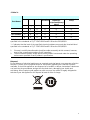
Material Contents Declaration
The recycling label shown on the product indicates the Hazardous Substances contained in
the product as the table listed below.
: See <Table 1>.
: See <Table 2>.
<Table 1>
Part Name
Hazardous Substances
Lead
Mercury
Cadmium
Hexavalent
Chromium
Polybrominated
Biphenyls/
Polybromodiphenyl
Ethers
Selected Phthalates
Group
Pb
Hg
Cd
Cr
6+
PBB/PBDE
DEHP/BBP/DBP/DIBP
PCBA
O O O O O O
CHASSIS
O O O O O O
ACCESSORY
O O O O O O
PACKAGE
O O O O O O
“O” indicates that the level of the specified chemical substance is less than the threshold level
specified in the standards of SJ/T
-11363-2006 and EU Directive 2011/65/EU.
“
” indicates that the level of the specified chemical substance exceeds the threshold level
specified in the standards of SJ/T
-11363-2006 and EU Directive 2011/65/EU.
Remarks:
The CE marking on product is a declaration of product compliance with EU
Directive 2011/65/EU.
Disposal
Do not dispose of electrical appliances as unsorted municipal waste, use separate collection
facilities. Contact your local government for information regarding the collection systems
available. If electrical appliances are disposed of in landfills or dumps, hazardous substances
can leak into the groundwater and get into the food chain, damaging your health and
well-being. When replacing old appliances with new one, the retailer is legally obligated to
take back your old appliances for disposal at least for free of charge.

v
<Table 2>
Part Name
Hazardous Substances
Lead
Mercury
Cadmium
Hexavalent
Chromium
Polybrominated
Biphenyls/
Polybromodiphenyl
Ethers
Selected Phthalates
Group
Pb
Hg
Cd
Cr
6+
PBB/PBDE
DEHP/BBP/DBP/DIBP
PCBA
O O O O O
CHASSIS
O O O O O
ACCESSORY
O O O O O
PACKAGE
O O O O O O
“O” indicates that the level of the specified chemical substance is less than the threshold level
specified in the standards of
SJ/T-11363-2006 and EU Directive 2011/65/EU.
“
” indicates that the level of the specified chemical substance exceeds the threshold level
specified in the standards of SJ/T
-11363-2006 and EU Directive 2011/65/EU.
1.
Chroma is not fully transitioned to lead-free solder assembly at this moment; however,
most of the components used are RoHS compliant.
2.
The environment-friendly usage period of the product is assumed under the operating
environment specified in each product’s specification.
Disposal
Do not dispose of electrical appliances as unsorted municipal waste, use separate collection
facilities. Contact your local government for information regarding the collection systems
available. If electrical appliances are disposed of in landfills or dumps, hazardous substances
can leak into the groundwater and get into the food chain, damaging your health and
well-being. When replacing old appliances with new one, the retailer is legally obligated to
take back your old appliances for disposal at least for free of charge.

vi

vii
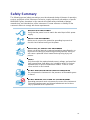
Safety Summary
The following general safety precautions must be observed during all phases of operation,
service, and repair of this instrument. Failure to comply with these precautions or specific
WARNINGS given elsewhere in this manual will violate safety standards of design,
manufacture, and intended use of the instrument. Chroma assumes no liability for the
customer’s failure to comply with these requirements.
BEFORE APPLYING POWER
Verify that the power is set to match the rated input of this power
supply.
PROTECTIVE GROUNDING
Make sure to connect the protective grounding to prevent an
electric shock before turning on the power.
NECESSITY OF PROTECTIVE GROUNDING
Never cut off the internal or external protective grounding wire, or
disconnect the wiring of protective grounding terminal. Doing so
will cause a potential shock hazard that may bring injury to a
person.
FUSES
Only fuses with the required rated current, voltage, and specified
type (normal blow, time delay, etc.) should be used. Do not use
repaired fuses or short-circuited fuse holders. To do so could
cause a shock or fire hazard.
DO NOT OPERATE IN AN EXPLOSIVE ATMOSPHERE
Do not operate the instrument in the presence of flammable gases
or fumes.
DO NOT REMOVE THE COVER OF THE INSTRUMENT
Operating personnel must not remove the cover of the instrument.
Component replacement and internal adjustment can be done
only by qualified service personnel.

viii
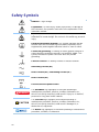
Safety Symbols
DANGER – High voltage.
Explanation: To avoid injury, death of personnel, or damage to
the instrument, the operator must refer to the explanation in the
instruction manual.
High temperature: This symbol indicates the temperature is
hazardous to human beings. Do not touch it
to avoid any personal
injury.
Protective grounding terminal: This symbol indicates that the
terminal must be connected to ground before operation of the
equipment to protect against electrical shock in case of a fault.
Functional grounding: To identify an earth (ground) terminal in
cases where the protective ground is not explicitly stated. This
symbol indicates the power connector does not provide
grounding.
Frame or chassis: To identify a frame or chassis terminal.
Alternating Current (AC)
Direct Current (DC) / Alternating Current (AC)
Direct Current (DC)
Push-on/Push-off power switch
The WARNING sign highlights an essential operating or
maintenance procedure, practice, condition, statement, etc.,
which if not strictly observed, could result in injury to, or death of,
personnel or long term health hazards.
The CAUTION sign highlights an essential operating or
maintenance procedure, practice, condition, statement, etc.,
which if not strictly observed, could result in damage to, or
destruction of, equipment.
The Notice sign highlights an essential operating or maintenance
procedure, condition, or statement.
WARNING
CAUTION

ix
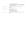
Revision History
The following lists the additions, deletions and modifications in this manual at each revision.
Date
Version
Revised Sections
Feb. 2009
1.0
Complete this manual
Apr. 2009
1.1
Modify the fuse spec. of AC Input in the section of “Specifications”.
Oct. 2009
1.2
Add the following sections:
- the section of “Three Phases Parallel Setting”
- the section of “Parallel Subsystem”
- the section of “PHASE Subsystem”
Modify the following sections:
- “Constant Power Mode” and “DAM Accuracy (>70Hz)” in the
section of “Specifications”
- the displayed menus in the section of “Local Operation”
- the displayed menus in the section of “BOTH”
- the displayed menus in the section of “CC Mode”
- the displayed menu in the section of “
Setting Timing Mode Values
for Transfer Time”
- the displayed menu in the section of “DC Load Simulation”
- the displayed menu in the section of “Short Circuit On/Off”
- the descriptions in the section of “Parallel Setting”
- the descriptions in the section of “Current Subsystem”
- the descriptions in the section of “Power Subsystem”
- the descriptions in the section of “Resistance Subsystem”
Mar. 2011
1.3
Add the chapter of “Verification”.
Dec. 2011
1.4
Add the description in the following sections:
- Note in the section of “The Front Panel”.
- Notices in the sections of “AC Load Simulation”, “DC Load
Simulation” and “DC Load Simulation -- Constant Voltage Mode”.
- Using limit of DC constant voltage mode.
- the section of “Transient Over Pressure Protection”.
Modify the following sections:
- the descriptions in the sections of “Inspection”, “Ip(max) Setting
and Automatic Bandwidth Adjustment (ABA) Mode” and “Parallel
Setting”.
Jul. 2012
1.5
Modify “CE Declaration”.
Nov. 2012
1.6
Add the section of “Power Fail (PWRFAIL)”.
Modify the following sections:
- the descriptions in the section of “Specifications”.
- the Notice content in the section of “Ip(max) Setting and
Automatic Bandwidth Adjustment (ABA) Mode”.
- Figure 3-18 in the section of “Parallel Setting”.
- Figure 3-19 and 3-20 in the section of “Three Phases Parallel
Setting”.
- the description of table in the section of “LOAD Subsystem”.
- command description of “[LOAD:]RESistance:LIMit?” in the

x
section of “Resistance Subsystem”.
- the description of Table 9-1 in the section of “Status Registers”.
- the description of Table 10-7 in the section of “
V monitor, Voltage
Measurement Verification”.
Mar. 2013
1.7
Modify the fuse specification to 3A, 250V in the section of
“Specifications”.
Oct. 2016
1.8
Modify “Declaration of Conformity”.
Mar. 2017
1.9
Modify the following:
- “Material Contents Declaration”。
- “CE Declaration of Conformity”.
Add “User Manual Customer Feedback”.
Jul. 2017
2.0
Delete the power cable of standard accessory table in the section of
“Inspection”.

Programmable AC/DC Electronic Load 63800 Series Operation & Programming Manual
xi
Table of Contents
1. General Information .................................................................................................. 1-1
1.1 Introduction ......................................................................................................... 1-1
1.2 Overview of Key Features ................................................................................... 1-1
1.3 Description .......................................................................................................... 1-1
1.4 Specifications ...................................................................................................... 1-2
1.5 Names of Parts ................................................................................................... 1-5
1.5.1 The Front Panel ....................................................................................... 1-5
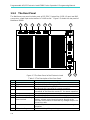
1.5.2 The Rear Panel ....................................................................................... 1-8
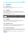
2. Installation ................................................................................................................. 2-1
2.1 Introduction ......................................................................................................... 2-1
2.2 Inspection ........................................................................................................... 2-1
2.3 Installing ............................................................................................................. 2-1
2.3.1 Preparation for Use ................................................................................. 2-1
2.3.2 Changing Line Voltage ............................................................................ 2-1
2.3.3 Turn-On Self-Test .................................................................................... 2-2
2.4 Application Connection ....................................................................................... 2-3
2.4.1 Load Connections ................................................................................... 2-3
3. Local Operation ......................................................................................................... 3-1
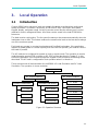
3.1 Introduction ......................................................................................................... 3-1
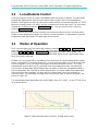
3.2 Local/Remote Control ......................................................................................... 3-2
3.3 Modes of Operation ............................................................................................ 3-2
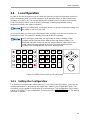
3.4 Local Operation................................................................................................... 3-3
3.4.1 Setting the Configuration ......................................................................... 3-3
3.4.2 External ON/OFF ..................................................................................... 3-6
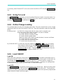
3.4.3 Going To Local ........................................................................................ 3-7
3.4.4 Online Change Loading ........................................................................... 3-7
3.4.5 Load ON/OFF .......................................................................................... 3-7
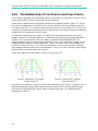
3.4.6 The Relationship of Crest Factor and Power Factor ................................ 3-8
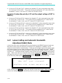
3.4.7 I
p
(max) Setting and Automatic Bandwidth Adjustment (ABA) Mode ....... 3-10
3.4.8 Lock Mode ............................................................................................. 3-11
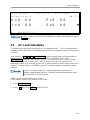
3.5 AC Load Simulation .......................................................................................... 3-13
3.6 AC Load Simulation -- Constant Current Mode ................................................. 3-15
3.6.1 BOTH .................................................................................................... 3-16
3.6.2 CF Only ................................................................................................. 3-18
3.6.3 PF Only ................................................................................................. 3-20
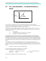
3.7 AC Load Simulation -- Constant Resistance Mode ............................................ 3-22
3.8 AC Load Simulation -- Constant Power Mode ................................................... 3-24
3.8.1 BOTH .................................................................................................... 3-24
3.8.2 CF Only ................................................................................................. 3-27
3.8.3 PF Only ................................................................................................. 3-28
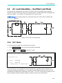
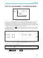
3.9 AC Load Simulation -- Rectified Load Mode ...................................................... 3-29
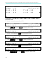
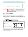
3.9.1 RLC Mode ............................................................................................. 3-29
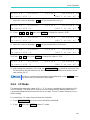
3.9.2 CP Mode ............................................................................................... 3-31
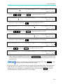
3.9.3 Inrush Current Mode.............................................................................. 3-34
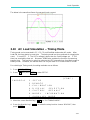
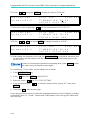
3.10 AC Load Simulation -- Timing Mode .............................................................. 3-37
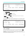
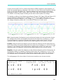
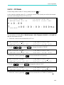
3.10.1 CC Mode ............................................................................................... 3-38
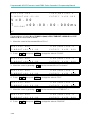
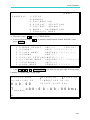
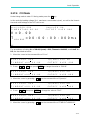
3.10.2 CR Mode ............................................................................................... 3-43
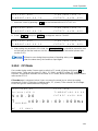
3.10.3 CP Mode ............................................................................................... 3-45
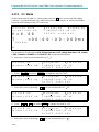
3.10.4 Rectified Load Mode.............................................................................. 3-46
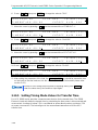
3.10.5 Setting Timing Mode Values for Transfer Time ...................................... 3-48

Programmable AC/DC Electronic Load 63800 Series Operation & Programming Manual
xii
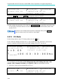
3.11 DC Load Simulation ...................................................................................... 3-51
3.12 DC Load Simulation -- Constant Current Mode ............................................. 3-53
3.13 DC Load Simulation -- Constant Resistance Mode ........................................ 3-55
3.14 DC Load Simulation -- Constant Voltage Mode ............................................. 3-57
3.15 DC Load Simulation -- Constant Power Mode ............................................... 3-59
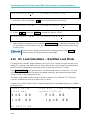
3.16 DC Load Simulation -- Rectified Load Mode.................................................. 3-60
3.16.1 Crest Factor in Rectified Mode Explanation ........................................... 3-62
3.17 DC Load Simulation -- Timing Mode.............................................................. 3-62
3.17.1 CC Mode ............................................................................................... 3-64
3.17.2 CR Mode ............................................................................................... 3-66
3.17.3 CP Mode ............................................................................................... 3-69
3.17.4 CV Mode ............................................................................................... 3-71
3.17.5 Rectified Mode ...................................................................................... 3-72
3.18 Voltage and Current Monitor ......................................................................... 3-75
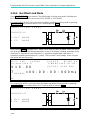
3.19 Short Circuit On/Off ....................................................................................... 3-75
3.20 Save/Recall Setting ....................................................................................... 3-76
3.21 Parallel Setting .............................................................................................. 3-78
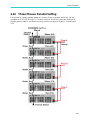
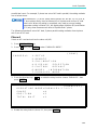
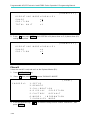
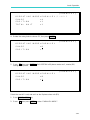
3.22 Three Phases Parallel Setting ....................................................................... 3-87
4. Measurements ........................................................................................................... 4-1
4.1 AC Load Simulation ............................................................................................ 4-2
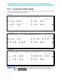
4.1.1 Constant Current Mode ........................................................................... 4-3
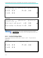
4.1.2 Constant Resistance Mode...................................................................... 4-4
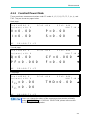
4.1.3 Constant Power Mode ............................................................................. 4-5
4.1.4 Rectified Load Mode................................................................................ 4-6
4.1.4.1 RLC Mode .......................................................................................................... 4-6
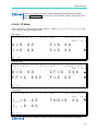
4.1.4.2 CP Mode ............................................................................................................ 4-7
4.1.4.3 Inrush Current Mode .......................................................................................... 4-8
4.2 DC Load Simulation ............................................................................................ 4-8
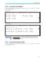
4.2.1 Constant Current Mode ........................................................................... 4-9
4.2.2 Constant Resistance Mode...................................................................... 4-9
4.2.3 Constant Voltage Mode ......................................................................... 4-10
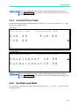
4.2.4 Constant Power Mode ........................................................................... 4-11
4.2.5 Rectified Load Mode.............................................................................. 4-11
5. Protection Features .................................................................................................. 5-1
5.1 Over Voltage Protection (OVP) ........................................................................... 5-1
5.2 Over Current Protection (OCP) ........................................................................... 5-1
5.3 Over Power Protection (OPP) ............................................................................. 5-1
5.4 Over Temperature Protection (OTP) ................................................................... 5-1
5.5 Fan Fail ............................................................................................................... 5-1
5.6 Out of Frequency Range (FREQ ERR) ............................................................... 5-2
5.7 Under Operating Voltage Protection (UVP) ......................................................... 5-2
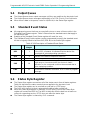
5.8 Load Fail (LDF) ................................................................................................... 5-2
5.9 Transient Over Pressure Protection(OVPP) ........................................................ 5-2
5.10 Power Fail (PWRFAIL) ........................................................................................ 5-2
6. Theory of Operation .................................................................................................. 6-1
6.1 General ............................................................................................................... 6-1
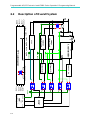
6.2 Description of Overall System ............................................................................. 6-2
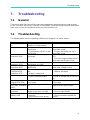
7. Troubleshooting ........................................................................................................ 7-1
7.1 General ............................................................................................................... 7-1
7.2 Troubleshooting .................................................................................................. 7-1
8. Remote Operation ..................................................................................................... 8-1
8.1 General Information ............................................................................................ 8-1

Programmable AC Electronic Load 63800 Series Operation & Programming Manual
xiii
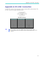
8.1.1 Setting the GPIB Address and RS-232C Parameters .............................. 8-1
8.1.2 Wire Connection of RS-232C .................................................................. 8-1
8.2 The GPIB Capability of the AC Load ................................................................... 8-1
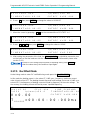
8.3 Introduction to Programming ............................................................................... 8-2
8.3.1 Conventions ............................................................................................ 8-2
8.3.2 Numerical Data Formats .......................................................................... 8-2
8.3.3 Boolean Data Format .............................................................................. 8-2
8.3.4 Character Data Format ............................................................................ 8-2
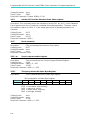
8.3.5 Basic Definition ........................................................................................ 8-3
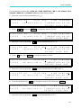
8.4 Traversal of the Command Tree ......................................................................... 8-4
8.5 Execution Order .................................................................................................. 8-4
8.6 SCPI Command Reference ................................................................................. 8-5
8.6.1 Common Command Dictionary ................................................................ 8-5
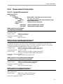
8.6.2 Measurement Subsystem ........................................................................ 8-7
8.6.2.1 Current Measurement ........................................................................................ 8-7
8.6.2.2 Frequency Measurement ................................................................................... 8-8
8.6.2.3 Power Measurement ......................................................................................... 8-8
8.6.2.4 Resistance Measurement .................................................................................. 8-9
8.6.2.5 Voltage Measurement ..................................................................................... 8-10
8.6.2.6 Time Measurement .......................................................................................... 8-11
8.6.2.7 RLC Measurement........................................................................................... 8-11
8.6.3 LOAD Subsystem .................................................................................. 8-12
8.6.3.1 Current Subsystem .......................................................................................... 8-14
8.6.3.2 Power Subsystem ............................................................................................ 8-16
8.6.3.3 Resistance Subsystem .................................................................................... 8-17
8.6.3.4 Voltage Subsystem .......................................................................................... 8-18
8.6.3.5 Crest Factor Subsystem .................................................................................. 8-18
8.6.3.6 Power Factor Subsystem ................................................................................ 8-19
8.6.3.7 RLC Subsystem ............................................................................................... 8-19
8.6.3.8 Inrush Current Subsystem ............................................................................... 8-20
8.6.3.9 DC Rectified Subsystem .................................................................................. 8-21
8.6.3.10 Time Subsystem ............................................................................................ 8-22
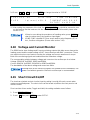
8.6.4 System Subsystem ................................................................................ 8-23
8.6.4.1 Recall Default Subsystem ............................................................................... 8-23
8.6.4.2 Remote Subsystem ......................................................................................... 8-23
8.6.4.3 Setup Subsystem............................................................................................. 8-24
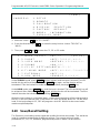
8.6.5 Parallel Subsystem ................................................................................ 8-25
8.6.6 PHASE Subsystem ............................................................................... 8-25
9. Status Reporting ....................................................................................................... 9-1
9.1 Introduction ......................................................................................................... 9-1
9.2 Register Information in Common ......................................................................... 9-1
9.3 Status Registers.................................................................................................. 9-2
9.3.1 Status Subsystem Commands ................................................................ 9-2
9.4 Output Queue ..................................................................................................... 9-4
9.5 Standard Event Status ........................................................................................ 9-4
9.6 Status Byte Register ........................................................................................... 9-4
9.7 Service Request Enable Register ....................................................................... 9-5
10. Verification ...................................................................................................... 10-1
10.1 Introduction ................................................................................................... 10-1
10.2 Equipment Requirement................................................................................ 10-1
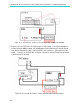
10.3 Test Environment Setup ................................................................................ 10-1
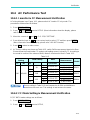
10.4 AC Performance Test .................................................................................... 10-3
10.4.1 I monitor & CF Measurement Verification .............................................. 10-3
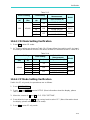
10.4.2 CC Mode Setting & Measurement Verification ....................................... 10-3
10.4.3 CR Mode Setting Verification ................................................................. 10-5

Programmable AC/DC Electronic Load 63800 Series Operation & Programming Manual
xiv
10.4.4 CP Mode Setting Verification ................................................................. 10-5
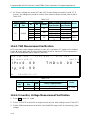
10.4.5 THD Measurement Verification .............................................................. 10-6
10.4.6 V monitor, Voltage Measurement Verification ........................................ 10-6
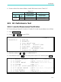
10.5 DC Performance Test ................................................................................... 10-7
10.5.1 I monitor Measurement Verification ....................................................... 10-7
10.5.2 CC Mode Operation & Measurement Verification .................................. 10-8
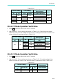
10.5.3 CR Mode Operation Verification ............................................................ 10-8
10.5.4 CP Mode Operation Verification ............................................................ 10-9
10.5.5 CV Mode Operation Verification ............................................................ 10-9
10.5.6 V_Monitor, Voltage Measurement Verification ..................................... 10-10
Appendix A: RS-232C Connection .................................................................................. A-1
Appendix B: Pin Assignment of TTL I/O Signals ........................................................... B-1
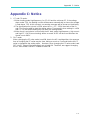
Appendix C: Notice .......................................................................................................... C-1

General Information
1-1
1. General Information
1.1 Introduction
This manual contains specifications, installation, operation, and programming instructions of
63800 series high power electronic loads. All the machines are tested according to safety
standard EN61010-1: TYPE POLLUTION II and INSTALLTION CATEGORY II.
1.2 Overview of Key Features
Local operation on front panel keypad.
Remote control via GPIB, RS-232C interfaces.
Photo-couple isolation supplies true floating Load.
Automatic fan speed control to reduce audio noise.
Operation modes: CC, CR, CP @ constant load modes; RLC, CP, Inrush Current @
rectified load modes; CC, CR, CP, CV, DC Rectified @ DC load simulation.
Programmable load value, power factor (PF) and crest factor (CF).
Minimum input resistance allows load to sink high current even with low input voltage.
10 sets of memories to save/recall user-definable setups.
16-bit A/D converter with precision measurement.
Short circuit simulation.
Isolated voltage and current monitoring waveforms output.
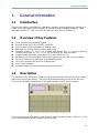
1.3 Description
The functions of the 63800 series loads are the same except the variations on input voltage,
load current, and power ratings. They provide simulated loading current for the test unit.
They can be operated independently in AC load simulation and DC load simulation.
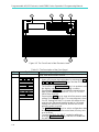
Figure 1-1 The Front Panel of the Electronic Load
There are two groups of keypads on the electronic load front panel shown in Figure 1-1. They
are Function keypad and Entry keypad from left to right.

Programmable AC/DC Electronic Load 63800 Series Operation & Programming Manual
1-2
1.4 Specifications
* The specifications of Load are listed from the next page on.
1. The equipment is for indoor use only.
2. The altitude up to 2000 meters is allowed to use the equipment.
3. All specifications are tested under 20°C ∼ 30°C except otherwise stated.
4. The range for operation temperature is 0°C ∼ 40°C.
5. The relative humidity is from 10% to 90%.
6. The specifications of current accuracy are tested after the input is applied
for 30 seconds.
7. The typical temperature coefficient is 100ppm.
This equipment is not intended for performing measurements on CAT III
or IV.
CAUTION

General Information
1-3
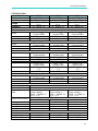
SPECIFICATION
Model
63802
63803
63804
Power
1,800W
3,600W
4,500W
Current
0 ∼ 18A
rms
(54 A
peak
)
0 ∼ 36A
rms
(108 A
peak
)
0 ∼ 45A
rms
(135 A
peak
)
Voltage
50 ∼ 350V
rms
(500
V
peak
)
50 ∼ 350V
rms
(500
V
peak
)
50 ∼ 350V
rms
(500
V
peak
)
Frequency
45 ∼ 440Hz, DC
45 ∼ 440Hz, DC
45 ∼ 440Hz, DC
AC Section
Constant Current Mode
Range
0 ∼ 18A
rms
,
Programmable
0 ∼ 36A
rms
,
Programmable
0 ∼ 45A
rms
,
Programmable
Accuracy
*1
0.1% + 0.2%F.S.
0.1% + 0.2%F.S.
0.1% + 0.2%F.S.
Resolution
2mA
5mA
5mA
Constant Resistance Mode
Range
2.77Ω ~ 2.5kΩ,
Programmable
1.39Ω ~ 2.5kΩ,
Programmable
1.11Ω ~ 2.5kΩ,
Programmable
Accuracy
0.5% + 0.5%F.S.
0.5% + 0.5%F.S.
0.5% + 0.5%F.S.
Resolution
*4
20µS
50µS
50µS
Constant Power Mode
Range
1,800W,
Programmable
3,600W,
Programmable
4,500W,
Programmable
Accuracy
0.2% + 0.3%F.S.
0.2% + 0.3%F.S.
0.2% + 0.3%F.S.
Resolution
0.375W
1.125W
1.125W
Crest Factor (under CC, CP modes)
Range*
2
1.414 ∼ 5.0,
Programmable
1.414 ∼ 5.0,
Programmable
1.414 ∼ 5.0,
Programmable
Accuracy
(0.5% / I
rms
) + 1%
F.S.
(0.5% / I
rms
) + 1%
F.S.
(0.5% / I
rms
) + 1%
F.S.
Resolution
0.005
0.005
0.005
Power Factor
Range
0 ∼ 1 lead or lag,
Programmable
0 ∼ 1 lead or lag,
Programmable
0 ∼ 1 lead or lag,
Programmable
Accuracy
1%F.S.
1%F.S.
1%F.S.
Resolution
0.001
0.001
0.001
Rectified Load Mode
Operating Frequency
45Hz ~ 70Hz
RLC mode
Parameter: I
p
(max), R
s
, L
s
, C, R
L
Constant Power
Mode
Parameter: I
p
(max),
Power setting =
200W ∼ 1,800W, PF
= 0.4 ∼ 0.75
Parameter: I
p
(max),
Power setting =
200W ∼ 3,600W, PF
= 0.4 ∼ 0.75
Parameter: I
p
(max),
Power setting =
200W ∼ 4, 500W, PF
= 0.4 ∼ 0.75
Inrush Current Mode
Parameter: I
p
(max), R
s
, L
s
, C, R
L
, Phase
80A (peak current)
160A (peak current)
200A (peak current)
R
s
Range
0 ~ 9.999Ω
0 ~ 9.999Ω
0 ~ 9.999Ω
L
s
Range
0 ~ 9999µH
0 ~ 9999µH
0 ~ 9999µH
C Range
100 ~ 9999µF
100 ~ 9999µF
100 ~ 9999µF
R
L
Range
2.77 ~ 9999.99Ω
1.39 ~ 9999.99Ω
1.11 ~ 9999.99Ω
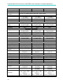
DC Section
Voltage Range
7.5V ~ 500V
7.5V ~ 500V
7.5V ~ 500V
Current Range
0A ~ 18A
0A ~ 36A
0A ~ 45A
Slew Rate
4 ~ 240A/ms
4 ~ 600A/ms
4 ~ 600A/ms

Programmable AC/DC Electronic Load 63800 Series Operation & Programming Manual
1-4
Rise Time
75µs
75µs
75µs
Min. Operating Voltage
7.5V
7.5V
7.5V
Operating Mode
CC, CV, CR, CP, DC Rectified
Short Circuit
Simulation
Use the CR mode loading under max. power rating.
Constant Current Mode
Range
0 ∼ 18A,
Programmable
0 ∼ 36A,
Programmable
0 ∼ 45A,
Programmable
Accuracy
*1
0.1% + 0.2%F.S.
0.1% + 0.2%F.S.
0.1% + 0.2%F.S.
Resolution
2mA
5mA
5mA
Constant Resistance Mode
Range
2.22Ω ~ 1kΩ,
Programmable
1.25Ω ~ 1kΩ,
Programmable
1.00Ω ~ 1kΩ,
Programmable
Accuracy
0.5% set + 0.5%F.S.
0.5% set + 0.5%F.S.
0.5% set + 0.5%F.S.
Resolution
*4
20µS
50µS
50µS
Constant Power Mode
Range
1,800W,
Programmable
3,600W,
Programmable
4,500W,
Programmable
Accuracy
0.2% + 0.3%F.S.
0.2% + 0.3%F.S.
0.2% + 0.3%F.S.
Resolution
0.375W
1.125W
1.125W
Constant Voltage Mode
Range
7.5V ∼ 500V,
Programmable
7.5V ∼ 500V,
Programmable
7.5V ∼ 500V,
Programmable
Accuracy
0.3% + 0.3%F.S.
0.3% + 0.3%F.S.
0.3% + 0.3%F.S.
Resolution
0.01V
0.01V
0.01V
Measurement Section
DVM Range
350V
rms
(500 V
peak
)
350V
rms
(500 V
peak
)
350V
rms
(500 V
peak
)
DVM Accuracy
0.1% + 0.1%F.S.
0.1% + 0.1%F.S.
0.1% + 0.1%F.S.
DVM Resolution
10 mV
10 mV
10 mV
DAM Range
18A
rms
(80 A
peak
)
36A
rms
(160.00 A
peak
)
36A
rms
(200.00 A
peak
)
DAM Accuracy
(<70Hz)
0.1% + 0.2%F.S. 0.1% + 0.2%F.S. 0.1% + 0.2%F.S.
DAM Accuracy (>70Hz)
*1
0.1%(1+CF
2
×kHz) +
0.2%F.S.
0.1%(1+CF
2
×kHz) +
0.2%F.S.
0.1%(1+CF
2
×kHz) +
0.2%F.S.
DAM Resolution
1.0 mA
2.5 mA
2.5 mA
True Power
Range
0 ~ 1,800W
0 ~ 3,600W
0 ~ 4,500W
Accuracy
0.2% + 0.3%F.S.
0.2% + 0.3%F.S.
0.2% + 0.3%F.S.
Apparent Power
Range
0 ~ 1,800VA
0 ~ 3,600VA
0 ~ 4,500VA
Accuracy
0.2% + 0.3%F.S.
0.2% + 0.3%F.S.
0.2% + 0.3%F.S.
Others parameters
*3
Q(VAR), CF, PF, Freq, R, I
p
-, I
p
+, THDv
Others
Vmonitor
±500V/±10V
(Isolated)
±500V/±10V
(Isolated)
±500V/±10V
(Isolated)
Imonitor ±80A/±10V (Isolated)
±200A/±10V
(Isolated)
±200A/±10V
(Isolated)
Protection
OCP: 19.2A
rms
;
OVP: 360V
rms
(DC:
510V
DC
);
OPP: 1,920W; OTP
OCP: 38.4A
rms
;
OVP: 360V
rms
(DC:
510V
DC
);
OPP: 3,840W; OTP
OCP: 48A
rms
;
OVP: 360V
rms
(DC:
510V
DC
);
OPP: 4,800W; OTP
Parallel Ability
Yes
Yes
Yes
Page is loading ...
Page is loading ...
Page is loading ...
Page is loading ...
Page is loading ...
Page is loading ...
Page is loading ...
Page is loading ...
Page is loading ...
Page is loading ...
Page is loading ...
Page is loading ...
Page is loading ...
Page is loading ...
Page is loading ...
Page is loading ...
Page is loading ...
Page is loading ...
Page is loading ...
Page is loading ...
Page is loading ...
Page is loading ...
Page is loading ...
Page is loading ...
Page is loading ...
Page is loading ...
Page is loading ...
Page is loading ...
Page is loading ...
Page is loading ...
Page is loading ...
Page is loading ...
Page is loading ...
Page is loading ...
Page is loading ...
Page is loading ...
Page is loading ...
Page is loading ...
Page is loading ...
Page is loading ...
Page is loading ...
Page is loading ...
Page is loading ...
Page is loading ...
Page is loading ...
Page is loading ...
Page is loading ...
Page is loading ...
Page is loading ...
Page is loading ...
Page is loading ...
Page is loading ...
Page is loading ...
Page is loading ...
Page is loading ...
Page is loading ...
Page is loading ...
Page is loading ...
Page is loading ...
Page is loading ...
Page is loading ...
Page is loading ...
Page is loading ...
Page is loading ...
Page is loading ...
Page is loading ...
Page is loading ...
Page is loading ...
Page is loading ...
Page is loading ...
Page is loading ...
Page is loading ...
Page is loading ...
Page is loading ...
Page is loading ...
Page is loading ...
Page is loading ...
Page is loading ...
Page is loading ...
Page is loading ...
Page is loading ...
Page is loading ...
Page is loading ...
Page is loading ...
Page is loading ...
Page is loading ...
Page is loading ...
Page is loading ...
Page is loading ...
Page is loading ...
Page is loading ...
Page is loading ...
Page is loading ...
Page is loading ...
Page is loading ...
Page is loading ...
Page is loading ...
Page is loading ...
Page is loading ...
Page is loading ...
Page is loading ...
Page is loading ...
Page is loading ...
Page is loading ...
Page is loading ...
Page is loading ...
Page is loading ...
Page is loading ...
Page is loading ...
Page is loading ...
Page is loading ...
Page is loading ...
Page is loading ...
Page is loading ...
Page is loading ...
Page is loading ...
Page is loading ...
Page is loading ...
Page is loading ...
Page is loading ...
Page is loading ...
Page is loading ...
Page is loading ...
Page is loading ...
Page is loading ...
Page is loading ...
Page is loading ...
Page is loading ...
Page is loading ...
Page is loading ...
Page is loading ...
Page is loading ...
Page is loading ...
Page is loading ...
Page is loading ...
Page is loading ...
Page is loading ...
Page is loading ...
Page is loading ...
Page is loading ...
Page is loading ...
Page is loading ...
Page is loading ...
Page is loading ...
Page is loading ...
Page is loading ...
Page is loading ...
Page is loading ...
Page is loading ...
Page is loading ...
Page is loading ...
Page is loading ...
Page is loading ...
Page is loading ...
Page is loading ...
Page is loading ...
Page is loading ...
Page is loading ...
Page is loading ...
Page is loading ...
Page is loading ...
Page is loading ...
Page is loading ...
Page is loading ...
Page is loading ...
Page is loading ...
Page is loading ...
Page is loading ...
Page is loading ...
Page is loading ...
Page is loading ...
Page is loading ...
Page is loading ...
Page is loading ...
Page is loading ...
Page is loading ...
Page is loading ...
Page is loading ...
-
 1
1
-
 2
2
-
 3
3
-
 4
4
-
 5
5
-
 6
6
-
 7
7
-
 8
8
-
 9
9
-
 10
10
-
 11
11
-
 12
12
-
 13
13
-
 14
14
-
 15
15
-
 16
16
-
 17
17
-
 18
18
-
 19
19
-
 20
20
-
 21
21
-
 22
22
-
 23
23
-
 24
24
-
 25
25
-
 26
26
-
 27
27
-
 28
28
-
 29
29
-
 30
30
-
 31
31
-
 32
32
-
 33
33
-
 34
34
-
 35
35
-
 36
36
-
 37
37
-
 38
38
-
 39
39
-
 40
40
-
 41
41
-
 42
42
-
 43
43
-
 44
44
-
 45
45
-
 46
46
-
 47
47
-
 48
48
-
 49
49
-
 50
50
-
 51
51
-
 52
52
-
 53
53
-
 54
54
-
 55
55
-
 56
56
-
 57
57
-
 58
58
-
 59
59
-
 60
60
-
 61
61
-
 62
62
-
 63
63
-
 64
64
-
 65
65
-
 66
66
-
 67
67
-
 68
68
-
 69
69
-
 70
70
-
 71
71
-
 72
72
-
 73
73
-
 74
74
-
 75
75
-
 76
76
-
 77
77
-
 78
78
-
 79
79
-
 80
80
-
 81
81
-
 82
82
-
 83
83
-
 84
84
-
 85
85
-
 86
86
-
 87
87
-
 88
88
-
 89
89
-
 90
90
-
 91
91
-
 92
92
-
 93
93
-
 94
94
-
 95
95
-
 96
96
-
 97
97
-
 98
98
-
 99
99
-
 100
100
-
 101
101
-
 102
102
-
 103
103
-
 104
104
-
 105
105
-
 106
106
-
 107
107
-
 108
108
-
 109
109
-
 110
110
-
 111
111
-
 112
112
-
 113
113
-
 114
114
-
 115
115
-
 116
116
-
 117
117
-
 118
118
-
 119
119
-
 120
120
-
 121
121
-
 122
122
-
 123
123
-
 124
124
-
 125
125
-
 126
126
-
 127
127
-
 128
128
-
 129
129
-
 130
130
-
 131
131
-
 132
132
-
 133
133
-
 134
134
-
 135
135
-
 136
136
-
 137
137
-
 138
138
-
 139
139
-
 140
140
-
 141
141
-
 142
142
-
 143
143
-
 144
144
-
 145
145
-
 146
146
-
 147
147
-
 148
148
-
 149
149
-
 150
150
-
 151
151
-
 152
152
-
 153
153
-
 154
154
-
 155
155
-
 156
156
-
 157
157
-
 158
158
-
 159
159
-
 160
160
-
 161
161
-
 162
162
-
 163
163
-
 164
164
-
 165
165
-
 166
166
-
 167
167
-
 168
168
-
 169
169
-
 170
170
-
 171
171
-
 172
172
-
 173
173
-
 174
174
-
 175
175
-
 176
176
-
 177
177
-
 178
178
-
 179
179
-
 180
180
-
 181
181
-
 182
182
-
 183
183
-
 184
184
-
 185
185
-
 186
186
-
 187
187
-
 188
188
-
 189
189
-
 190
190
-
 191
191
-
 192
192
-
 193
193
-
 194
194
-
 195
195
-
 196
196
-
 197
197
-
 198
198


Chroma 63800 Series Operation & Programming Manual
- Category
- Measuring, testing & control
- Type
- Operation & Programming Manual
Ask a question and I''ll find the answer in the document
Finding information in a document is now easier with AI
Related papers
-
Chroma A620027 Operating & Programming Manual
-
 Chroma 62000H Series Operating & Programming Manual
-
 Chroma 62150H-600 Operating & Programming Manual
-
 Chroma 61705 User manual
-
 Chroma 19572 User manual
-
Chroma 61503 User manual
-
 Chroma 2238 User manual
-
 Chroma 16502 User manual
-
 Chroma 8000 User manual
-
 Chroma 19072 Quick start guide


Other documents
-
Anritsu MS9710C Operating instructions
-
SEFRAM BK 8500B Series User manual
-
Itech Power meter [IT9121, IT9121H, IT9121C, IT9121E] User manual
-
Tektronix T-226B3036 User manual
-
B&K Precision Model 9832 Programming Manual
-
VOLTCRAFT DSP-3005 User manual
-
VOLTCRAFT DSP Series User manual
-
 Scientific DCL Series Owner's manual
-
 Setra Systems MicroCal™ Pressure Transducer Calibrator Operating instructions
-
Rotel RLC-1040 Owner's manual

