American Standard 3052OD.709.ARL-PC Installation guide
- Type
- Installation guide

1
754818-100 Rev. A
THANK YOU...
for selecting an American Standard bath. Your new bath is shipped to you after careful inspection. The
combination tub version is completely assembled with pump, motor, and system piping. All you need to finish
the combination tub installation are your selected fittings and electrical connections.
To ensure maximum performance and pleasure from this product, please follow the instructions and cautions.
©
AS Americas Inc. 2014
All product names listed herein are trademarks of AS Americas Inc. unless otherwise noted.
WALK-IN BATH
INSTALLATION INSTRUCTIONS
AND OWNER’S MANUAL
MODEL NUMBERS:
3052OD.X0X
C3052OD.X0X
3052D.XXX
C3052D.XXX
3252OD.X0X
C3252OD.X0X
SSXOD5230
SSXOD5230C
SSXOD5232
SSXOD5232C
ST5230D
ST5232DC

2
754818-100 Rev. A
You are now the owner of a walk-in bathtub from the most trusted name in plumbing.
We thank you for your purchase. Your American Standard
®
walk-in bath is a true
investment in your health and peace of mind.
Customer Support: (866) 423-0800
CONGRATULATIONS!

754818-100 Rev. A
3
OWNER’S MANUAL
TABLE OF CONTENTS:
UNPACKING THE UNIT...................................................................................... Page 4
RESPONSIBILITIES OF THE INSTALLER ......................................................... Page 5
TESTING YOUR TUB BEFORE INSTALLATION................................................. Page 6
INSTALLATION PREPARATION .......................................................................... Page 7
ELECTRICAL INSTALLATION............................................................................. Page 8
INSTALLATION PROCEDURES..................................................................... Page 9-17
SAFETY INSTRUCTIONS..................................................................................Page 18
OPERATING INSTRUCTIONS..................................................................... Page 19-20
CLEANING & MAINTENANCE.......................................................................... Page 21
WARRANTY...................................................................................................... Page 22
TROUBLESHOOTING.................................................................................. Page 23-25

4
754818-100 Rev. A
OWNER’S MANUAL
1. FIRST, inspect the carton for damage: CAREFULLY DOCUMENT AND PHOTOGRAGH ALL PERCEIVED
DAMAGE. Report all damage claims to customer service at 1-866-423-0800.
2. DO NOT LIFT THE TUB BY THE PLUMBING. Doing so can result in leaks, for which the installer is
responsible. All Walk-In Tubs are water tested before they leave our factory and the bathtub you have
purchased has passed inspection.
3. Immediately inspect the unit for damage even if there is no carton damage. All product damage must be
reported within 72 hours of receipt from American Standard
®
. Once the unit is installed, surface damages will
be assumed to be installation-related if not reported prior to installation. Installers are also responsible
for damage that occurs once the unit is placed in its niche.
NOTE: Remove all packaging material except for the protective plastic. This has been placed on the tub at
the factory to eliminate abrasions from handling. Thisshould only be removed at final clean up.
4. Inspect the plumbing for any fittings that may have loosened in transit.
5. Read the following instructions completely before installing this product. If the home-owner or installer has any
questions, please call us at 1-866-423-0800.
6. You must follow all the instructions in this manual.
FAILURE TO READ AND COMPLY WITH ALL INSTRUCTIONS CAN RESULT IN PRODUCT DAMAGE
OR INJURY TO BOTH INSTALLER AND HOMEOWNER. IT WILL ALSO RESULT IN
ASSUMPTION OF ALL
LIABILITY BY SAID INSTALLER.
UNPACKING THE UNIT

754818-100 Rev. A
5
OWNER’S MANUAL
The Installer must inspect and water test the product prior to installation to ensure the unit is free of defect
and /or damage. In the event of a problem, the unit must not be installed. If the packaging or product has
been damaged, please call immediately at 1-866-423-0800.
This product has been listed by INTERTEK / ETL and IAPMO / C UPC. The product has been tested and
complies with the following standards and guidelines: IAPMO /C UPC, UL-1795, ANSI Z-124.1.2,
ASME A 112.19.7, ASME A 112.19.15 & CSA B-45. The installer is responsible for compliance to
state and local codes.
This product is designed to be installed by a licensed tradesperson. Licensed plumbers and electricians
should be employed to insure proper installation. Installer assumes all liabilities for installation procedures.
Although American Standard
®
has taken reasonable precautions to ensure that the Quick Drain
TM
is suitable for
residential plumbing; it is the responsibility of the installer to insure that the plumbing is acceptable for use of
the Quick Drain
TM
. American Standard® does not accept responsibility for damage arising from use of the
Quick Drain
TM
.
Only accessories authorized by manufacturer should be used with this product.
RESPONSIBILITIES OF THE INSTALLER
INSTRUCTIONS PERTAINING TO RISK OF FIRE,
ELECTRICAL SHOCK OR INJURY TO PERSONS
SAVE THESE INSTRUCTIONS!
WARNING! ALL INSTRUCTIONS LISTED IN THIS MANUAL SHOULD BE READ AND FOLLOWED CAREFULLY.
A
LL PRECAUTIONS PERTAINING TO RISK OF FIRE, ELECTRIC SHOCK, OR INJURY TO PERSONS MUST BE
UNDERSTOOD AND EXPLAINED TO OWNER.
TO REDUCE THE RISK OF INJURY, CHILDREN OR PERSONS WITH INFIRMITIES MUST NOT BE PERMITTED
TO USE THIS PRODUCT WITHOUT CLOSE AND CONTINUOUS SUPERVISION.
RESPONSIBILITIES OF THE INSTALLER

6
754818-100 Rev. A
OWNER’S MANUAL
1.
All American Standard
®
walk-in baths are 100% water tested at the factory and have passed inspection.
Transportation and mishandling may loosen fittings and cause leaks. It is therefore necessary to
test the
bathtub while there is access to all sides of the bath.
2.
The unit needs to be filled with water and inspected for leaks along the door as well as the whirlpool and
air systems if equipped. The inspection needs to be performed with and without the whirlpool and / or ai
r
systems operating. It is best to test the unit outside by filling with a garden hose.
a. Place the tub on a completely flat surface in an area where it may be drained after testing.
b. Using a clean rag and warm water wipe down seal to insure it is free of debris.
c. Seal the drain hole (this can be done with tape) and fill the tub to at least three inches above
the highest jet, or to the bottom of the safety bar if no jets are present.
d. Allow the water to stand in tub for 30 minutes and then inspect all plumbing and seals for leaks.
e. Using appropriately rated three-prong extension cords, all plugged in to separate outlets,
operate all electrical components (air blower, water pump, and heater if applicable) for another
30 minutes and inspect for leaks again. Inspect the unions around the pump and heater.
f. If a leak persists at a union after tightening, it may have been over-tightened or might have a
displaced O-ring. Disassemble it and make sure the O-ring was seated properly. Do the same
if a leak persists at the heater. Verify that the heater threads match the pipe threads.
g. Ensure that all jets are open and working, some jets are adjustable for both flow rate and
direction of flow. The jet water flow rate is adjusted by turning either the outside ring or the
inside nozzle clockwise or counterclockwise. Some jets are not adjustable at the jet face, but
can be adjust by the “Leg’s Only Massage”. The “Legs Only Massage” Valve is located near
the seat. (If equipped.) .
3.
If the pump/blower/lights/heater does not operate:
a. Check the breaker to ensure that power is on and make sure that any cables and / or air lines
connecting the control boxes to the switches and pumps are firmly attached. Verify the correct
electrical circuit and amps of the electrical cord.
b. Go to Trouble Shooting Guidelines. (See pages 24-26.)
c. Do not run any pumps unless the tub is filled with water to the proper level. Damage due to
dry operation of pumps is not covered under the warranty period. (See pg. 23.)
Failure to perform these tests before installation will make the installer liable for future repair costs.
TESTING YOUR WALK-IN TUB BEFORE INSTALLATION

754818-100 Rev. A
7
OWNER’S MANUAL
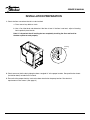
1.
Check the floor area where the tub is to be installed.
a. Clean area of any debris or trash.
b. Use a 5 or 6-foot level and determine if the floor is level. If the floor is not level, adjust all leveling
feet to perfectly level the tub.
Note: It is important that all leveling feet are completely touching the floor and level for
the door system to work properly.
2.
Check to ensure that the drain piping has been “roughed-in” at the proper location. See specification sheets
(installation detail) included in this manual.
3.
Ensure that the proper electrical service has been installed at the pump location. See electrical
requirements in the manual. (See page 8.)
INSTALLATION PREPARATION
Leveling
Feet

8
754818-100 Rev. A
OWNER’S MANUAL
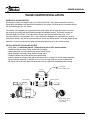
All electrical wiring must be installed in accordance with the National Electrical Code and with all local codes.
All wiring shall be done by a qualified electrician. Run one, two or three branch circuits (as required) from the
main electrical service panel to the pump area of the framing structure to provide power to the unit.
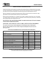
Electrical components have specific wiring requirements. Refer to the matrix below for the electrical supply
requirements for the whirlpool bathtub and factory installed components.
Branch circuits must be rated for 110 – 120 volts. Use 12 Gauge, 3 conductor cable for the circuits. If the length
run exceeds 100 feet, check with local codes for requirements. Install moisture proof junction box(s) 6" above the
floor at the pump end of the framing for each circuit.
DO NOT INSTALL THE JUNCTION BOX(S) WHERE IT CAN BE REACHED WHILE SITTING OR STANDING
IN THE TUB OR TOUCHING THE FAUCETS.
QUICK DRAIN
®
, LIGHTS, WHIRLPOOL, AIR SPA, COMBO & HEATER ELECTRIAL REQUIREMENTS
This section lists the factory installed components of the Whirlpool and/or Air Spa Systems.
Note the required number of circuits and their rating for the Whirlpool & Air Spa unit you are
planning to install.
ELECTRICAL REQUIREMENTS FOR FACTORY INSTALLED COMPONENTS
ELECTRICAL INSTALLATION
Electrical Rating Electrical Rating Dedicated
Systems Circuit 1 Circuit 2 Circuit
Soaker w / Quick Drain
®
15 Amp GFCI
Soaker w / Light 15 Amp GFCI
Soaker w / Quick Drain
®
w / Light 15 Amp GFCI
Whirlpool or Air Spa 15 Amp GFCI
Whirlpool or Air Spa w / Light 15 Amp GFCI
Whirlpool or Air Spa w/ Quick Drain
®
15 Amp GFCI 15 Amp GFCI
Whirlpool or Air Spa w/ Light & Quick Drain
®
15 Amp GFCI 15 Amp GFCI
Whirlpool & Air Spa (Combo) 15 Amp GFCI 15 Amp GFCI
Whirlpool & Air Spa (Combo) w/ Light 15 Amp GFCI 15 Amp GFCI
Whirlpool & Air Spa (Combo) w/ Quick Drain
®
20 Amp GFCI 15 Amp GFCI
Whirlpool & Air Spa (Combo) w/ Light & Quick Drain
®
20 Amp GFCI 15 Amp GFCI
Whirlpool Inline Heater - Dedicated Circuit 15 Amp GFCI
All electrical connections must be carried out by a certified electrician
in accordance with local electricalrequirements and codes.

754818-100 Rev. A
OWNER’S MANUAL
9
WARNING: When installing whirlpool massage baths, air spa baths, combo baths, or Quick Drain
®
equipped baths, the following precautions must be followed:
WARNING: Danger: Risk of electrical shock; connect components to separate circuits, EACH protected
by a ground fault circuit interrupter (GFCI)
WARNING: Installation must provide access for servicing the pump and motor (all American Standard
®
walk-in baths come with access panels for the pump, motor and faucet).
1. Install tub waste/overflow according to instructions included with the provided kits. The Gel Coat Series
requires the installation of a door drain with check valve. The check valve and tubing must be installed
horizontal to the floor. Some installations will require the purchase of additional fittings.
2. American Standard Faucet Installation # 9FHS-CH
• Review the installation instructions packed with the faucet set.
• Mask off the tub’s deck with a protective tape.
• Locate and mark the center line of the overflow fitting
• Locate and mark 1-1/2" line either side of the tub’s center line to establish the overflow clearance.
• Follow the drill template and faucet installation instructions.
3. Other Faucet Model and / or Brand
• Review the installation instructions packed with the faucet set.
• Mask off the tub’s deck with a protective tape.
• Locate and mark the center line of the overflow fitting
• Locate and mark 1-1/2" line either side of the tub’s center line to establish the overflow clearance.
• Verify the first two component mounting clearance on either side of the waste overflow as well as
above and below the tub’s deck.
• Verify the remaining component mounting clearance on both sides of the overflow as well as above
and below the tub’s deck.
• It is recommended the hand held shower be installed on the corner closest to the wall to prevent water
from leaking off the deck and on to the floor.
4. Install the optional in-line water heater per manufacturer’s instructions.
5. Standard Walk-In Bath Installation — After framing is complete, set product in place to check fit and make
certain that the tub can be properly leveled. (Caution: If the bathtub is not resting on all leveling feet, water
will not drain properly and this may cause the door to leak). Secure tub frame to the studs using metal
straps. (Not provided.)
5a. Fire-Rated Drywall — If fire-rated drywall is specified, the finished fire-rated wall must be in place before
the tub is installed. The dimensions of the framing structure must be increased by the thickness of firerated
drywall.
INSTALLATION PROCEDURES
!
!
!

10
754818-100 Rev. A
OWNER’S MANUAL
WARNING:
Never allow the weight of the tub to be supported by wood support stringers and do not use
integral tile flange (if equipped) to screw or nail in place,
as this will result in product failure and will
void the warranty.
6.
Verify the product is completely level by checking tub deck surface and ensure all leveling feet are
touching the ground.
7.
Electrical connection is made by simply plugging each cord into the GFCI outlet.
8
. After plumbing and electrical connections have been made, the tub and door seal should be cleaned of dirt
and debris. Use warm water and a non abrasive cleaner for clean up.
9.
Installation is not complete until the bathtub has been water-tested in place and does not leak.
INSTALLATION PROCEDURES
(continued)

754818-100 Rev. A
11
OWNER’S MANUAL
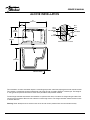
Tubs installed in an alcove installation require a raised flange to prevent water from seeping past the tub and into the wall.
Tubs without a raised flange shall be installed with a tile flange kit such as model: 9FLNG or a similar type. The flange kit
is a long plastic strip that fits onto the rim of the tub to provide the leak protection needed.
The tile flange should be installed on the tub before it is placed in the alcove. Install the tile flange along all sides of the
tub where the wall will be. Measure to fit and miter cut the flange corners. The flange should be attached to the tub with
a silicone adhesive.
Warning: Never attempt to nail or screw thru the tub as this will result in product failure and will void the warranty.
ALCOVE INSTALLATION
52"
(1321mm)
40"
(1016mm)
13"
(330mm)
16-1/2"
(419mm)
30"
(762mm)
ROUGH FLOOR
WALL
STUD
GALVANIZED
NAIL
TILE
FLANGE
NON-INTEGRAL FLANGE
TUB
SILICONE
TILE
DRY
WALL

12
754818-100 Rev. A
OWNER’S MANUAL
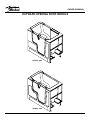
OUTWARD OPENING DOOR MODELS
SERIES: 3252
SERIES: 3052

754818-100 Rev. A
13
OWNER’S MANUAL
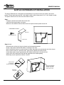
The Acrylic Extension Kit is designed to accommodate all acrylic walk-in tubs to fit within a 60" alcove
pocket. The top panel measures 30" x 20" (depth x width) and the front panel 37-1/2" x 20" (height x width).
The panels must be trim to fit the unit within the 60” alcove.
Step 1
• Temporary locate the tub within the alcove walls.
• Level the tub along the deck and apron.
• Measure and record the distance from the tub and apron to the adjacent alcove wall.
Step 2, 3 & 4
• Mask off and mark the trim lines for the top and front extension panels.
• Using a high speed carbide tooth blade, cut along the trim lines
• Mark a horizontal line that is parallel to the tub’s deck along the back and adjacent wall of the alcove.
• Mark a vertical line that is parallel to tub’s apron on the adjacent wall of the alcove.
• Install three wood stringers approximately 3/8" below the horizontal and vertical lines.
• Verify the fit of the front panel and then the top panel to the alcove opening.
• Shimming may be required to achieve a level fit.
ACRYLIC EXTENSION KIT INSTALLATION
Draw cut line
accordingly to
measured distance
Place wood stringers
3/8" below top deck
and 3/8" away from
end of alcove wall
Cut panels
along line
Top Panel
Front Panel
Self Tapping Screw
EXTENSION KIT PARTS
Measure
Distance

14
754818-100 Rev. A
OWNER’S MANUAL
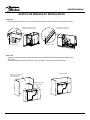
Step 5 & 6
• Remove the tub from the alcove and install the front and then top panel with the self tapping fasteners.
Step 7 & 8
• Apply the temporary clamps to help support the front and top panels while re-locating the tub back into
the alcove.
• Remove temporary clamps, check level, shim if necessary, and seal in panels with silicone.
ACRYLIC EXTENSION KIT INSTALLATION
Predrill screw holes and
attach front panel to apron
Apply silicone between
wood stringers and
extension panels
Predrill screw holes and
attach top deck of tub
Self tapping screw
Self tapping screw
FINAL INSTALL
Slide tub into final
install position

754818-100 Rev. A
15
OWNER’S MANUAL
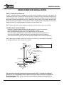
DRAIN / OVERFLOW INFORMATION
A drain / overflow assembly is provided with the tub must be installed on the bath, water tested and
connected to the sanitary system of the house. Some drain / overflow kits are packed with the waste flange,
strainer, overflow cover, and fasteners, packed separately within the kit to protect the trim finish. Follow the
installation instructions provided with the drain / overflow kit. After the drain is fully installed, test the unit for
proper drainage. If the unit does not drain properly, rectify the condition before proceeding with installation.
American Standard
®
is not responsible for the removal or re-installation costs.
NOTE: All gel coat models require additional installation of the door drain to the waste overflow.
CONNECTION OF THE QUICK DRAIN
®
• Quick Drain
®
System requires the connection to a minimum 1-1/2" sanitary drain line.
• Use UPC Approved PVC Glue, Primer, and Schedule 40 1-1/2" pipe.
• Do not change or modify the location and or piping of the Back Flow Manifold
• The sanitary tee is installed directly above the drain tee with clearance not greater than 1".
• Dry fit the drain overflow assembly to the sanitary drainage pipe and check for proper fit.
• Glue the Quick Drain
®
Fittings, pipe and drain overflow assembly to the sanitary drainage pipe.
NOTE: Water tight installation of the waste / overflow is the installer’s responsibility. Drain leakage
i
s excluded from Safety Tubs warranty of this product.
We have taken reasonable precautions to ensure the Quick Drain
®
is suitable for residential
plumbing. It is the responsibility of the installer to insure the sanitary system is acceptable for
the use of the Quick Drain. We do not accept responsibility for damage arising from the use
of the Quick Drain.
DRAIN OVERFLOW INSTALLATION
Sanitary tee
Over flow
Drain tee
Drain
cable
Drain
Stopper
ST 90˚elbow
P-trap
Flow direction
To check valve
Pre-installed back flow manifold
Supplied
Not supplied
Back flow manifold
from Quick Drain pump
Drain Shoe
Gasket
Strainer
Nut
Reducer
1-1/2"x1"
Sub floor
Drain
cable

16
754818-100 Rev. A
OWNER’S MANUAL
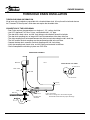
THRESHOLD DRAIN INFORMATION
All gel coat walk-in bathtubs are provided with a threshold door drain. All acrylic walk-in bathtubs feature
the “Patented T5 Door System” which does not require the threshold drain.
CONNECTION OF THE DOOR DRAIN
•
Door Drain requires the connection to a minimum 1-1/2" sanitary drain line.
•
Use UPC Approved PVC Glue, Primer, and Schedule 40 1-1/2" pipe.
•
The door drain, check valve, and 3/8" vinyl tubing are installed on the walk-in bathtub
•
The door drain coupling has an integral 3/8" barb for connection of the door drain line.
•
The drain coupling must be located between the drain tee and shoe along the tub’s drain line.
•
The 3/8” barb on the drain coupling must be positioned parallel to the sub floor.
•
Connect the door drain assembly and drain coupling with 3/8" vinyl tubing.
•
Verify the coupling barb, check valve, and 3/8" tubing are horizontal to the floor.
•
Glue all components and tubing in place use PVC Glue.
THRESHOLD DRAIN INSTALLATION
Drain tee
Coupler with
3/8" barb
Inline check valve
Note: valve & tubing must be installed angled
downward toward drain for proper drainage.
Drain cable
Overflow
P-trap
Drain shoe
Door drain
Door
DOOR DRAIN ASSEMBLY
Tub wall
Sub floor
To door drain
To drain shoe
COUPLER with 3/8" BARB

754818-100 Rev. A
17
OWNER’S MANUAL
WHIRLPOOL IN-LINE HEATER
All whirlpool systems are deigned with an In-Line Heater Blank. The threads and union set on the
heater blank and heaters are specifically designed for our system. All other heaters and heater blanks
will not interchanges with our system.
The heaters are equipped with a preset pressure switch which will not allow the heater to turn on i
f
the pump is not running with water flowing through the whirlpool system. The heater includes an
exclusive High Limit Switch. This safety circuit will not false trip from the hot tap water. It will
turn off the heater is the thermostat fails. If your whirlpool is equipped with adjustable jets, or other
flow control systems, the pre-set pressure switch may not activate the heater. To assure proper heater
operation, all jets may need to fully open with the pump operating at or near maximum flow
.
INSTALLATION OF THE IN-LINE HEATER
•
Verify there is a dedicated 120 volt, 15 Amp Circuit with a GFCI outlet available.
•
Located the Ready Heater Fitting on the walk-in bathtub.
•
Loosen the union nuts and remove the Heater Ready Fitting.
•
Verify the heater and union fitting threads are the same.
•
Placed the ribbed side of the gasket to the union fitting.
• Insert the heater and slowly hand tighten the union nuts to a smug fit to insure proper alignment.
•
Once the heater alignment is verified, give a 1/4 turn to each union nut to insure a good seal.
•
Fill the tub with water and check for water leaks with and without the whirlpool pump running.
INLINE HEATER INSTALLATION
Union fitting Rubber gasket
Align rubber gasket
ring with groove on
union fitting
To dedicated
120V, 15AMP circuit
Heater
Heater blank
Motor

18
754818-100 Rev. A
OWNER’S MANUAL
INSTRUCTIONS PERTAINING TO RISK OF FIRE,
ELECTRICAL SHOCK OR INJURY TO PERSONS
WHEN USING THIS UNIT, BASIC PRECAUTIONS SHOULD ALWAYS BE FOLLOWED.
WARNING: Risk of personal injutry. Use this unit for its intended use as described in this manual.
DO NOT use attachments not recommended by the manufacturer.
WARNING: Risk of personal injutry. To avoid injury, exercise caution when entering or exiting your
walk-in bath.
WARNING: Risk of personal injutry. To reduce the risk of injury, do not permit children or persons with
infirmities to use this product unless they are closely supervised at all times.
WARNING: Risk of hyperthermia and possible drowning. People using medications, herbal remedies,
sleep aids, and /or having adverse medical history should consult a physician before using this product.
WARNING: Risk of personal injutry. Water temperatures over a 100˚ F (38˚ C) may be hazardous to your
health. Check and adjust water temperature for your personal comfort.
WARNING: No food or alcoholic beverages. Use of your bathtub immediately after meals is not
recommended. Avoid alcohol consumption before or during the bathing. Alcoholic beverages can cause
drowsiness or hyperthermia resulting in loss of consciousness or even drowning.
WARNING: Pregnancy. If you are or think you may be pregnant, consult your doctor before using
the bathtub.
WARNING: Risk of personal injutry. Risk of electric shock; do not permit electric appliances (such as a hair
dryer, lamp, telephone, radio or television) within four feet of this bathtub.
WARNING: Risk of personal injutry. Never drop or insert any objects into any openings.
WARNING: Risk of personal injutry. Do not operate this unit without the guard over the suction fittings.
The unit must be connected only to a supply circuit that is protected by a ground-fault circuit-interrupter (GFCI).
Such a GFCI should be provided by the installer and should be tested on a routine basis. To test the GFCI, push
the test button. The GFCI should interrupt power. Push the reset button. Power should be restored. If the GFCI
fails to operate in this manner, there may be a ground current flowing, indicating the possibility of an electric
shock.
Do not use this massage bathtub. Disconnect the whirlpool bathtub and have the problem corrected by
a qualified service representative before using.
To reduce the risk of electrical shock, the dedicated electrical supply circuit(s) must be grounded. To do this,
connect the third leg of the 3-conductor wiring cable to the grounding terminal of the electrical service panel
an
d run continuously to the green grounding screw on the GFCI or electrical receptacle in the wiring compartment.
IMPORTANT SAFETY INSTRUCTIONS
!
!
!
!
!
!
!
!
!
!

754818-100 Rev. A
19
OWNER’S MANUAL
1. Enter your American Standard
®
walk-in bath, close the door, place handle in down position, and fill the bath
to at least 2 inches above the highest jet before activating the whirlpool pump (if equipped). Do not apply
excessive pressure when placing the handle in the close position. Do not put weight on the door when
entering and exiting the tub. It is recommended to leave the door in the open position when the tub
is not in use.
2. If your American Standard
®
walk-in bath is equipped with Whirlpool Jets, Air Spa, or Combo system, the pump
or blower is operated by the push button switch labeled “Jets” or “Air”. Both the number of buttons and their
assorted functions vary. Do not depress the button(s) repeatedly and/or rapidly as all function(s) are controlled
electronically. It may take a few seconds before any change becomes perceptible. Refer to massage
instructions sheet for more information on the controls.
3. If your American Standard
®
walk-in bath is equipped with whirlpool jets, you can adjust the direction and flow
rate of the jets to your liking by moving the nozzle for direction and turning the outside ring or the nozzle
clockwise or counterclockwise for the flow rate. Some jets are notadjustable at the jet face, but can be
adjusted by the “Legs Only Massage” valve located near the seat. (If equipped.)
4
. The Legs Only Massage (whirlpool & combo systems only) opens and closes the jets above the seat which
allows you to fill the tub half-way and operate only the lower whirlpool jets. The Legs Only Massage valve
must be closed when filling the tub half-way and operating the whirlpool. Failure to close the valve, when filling
the tub half-way will result in water shooting out of the jets above the seat when the pump is activated.
(If equipped.)
5. If your American Standard
®
walk-in bath is equipped with an Air Spa system, you can activate the heated
blower by pushing the push button on the deck. Push the button to turn on / off and cycle for the
various speeds.
6. If your American Standard
®
walk-in bath is equipped with an in-line heater, the heating element will come on
automatically, but only when the whirlpool system is turned on. This heater is designed to extend the
comfortable bathing time, but does not reheat the bath water.
7. If your American Standard
®
walk-in bath is equipped with the Automatic Tub Clean System - Ozone, the
system will turn on automatically when the whirlpool system is turned on.
8. If your American Standard
®
walk-in bath is equipped with the Quick Drain
®
, this system has its own
dedicated pump, suction and switch to activate the drain. Simply open the traditional drain system
(turn the overflow) and then press the Quick Drain
®
on/off switch to activate the drain. When the
water falls below the suction guard, press the control switch to turn the drain system off.
SAVE THESE INSTRUCTIONS! OPERATING INSTRUCTIONS

20
754818-100 Rev. A
OWNER’S MANUAL
9. If your American Standard
®
walk-in bath is equipped with Chromatherapy lights, the lights have a
dedicated control button. Pressing the control button off and back on will change the color of light.
10. If any factory-installed fittings have been removed, do not operate the unit. A safety hazard may have
been created by this modification. Seek the help of a qualified professional.
11. DO NOT use bubble bath or Epsom salts when any pumps are operating. Bath oils may be used;
however, their use will require more frequent purging and cleaning of the whirlpool and/or air spa systems.
12. Both whirlpool and air spa systems are designed so that water will drain from the plumbing after each use.
13. There are no user-serviceable parts located under the tub.
PURGE CYCLE
All air blowers are equipped with a purge cycle to remove residual water from the lines. The purge cycle will
begin approximately 20 minutes after the unit is initially turned off and will continue for several minutes.
Do not be alarmed when the cycle begins.
IN-LINE HEATERS
If your bathtub is equipped with an optional in-line heater it will operate only when the pump is on.
Note: the in-line heater is designed to keep your water warmer longer but is not designed to increase
the water temperature. Heat settings are not adjustable.
SAVE THESE INSTRUCTIONS! OPERATING INSTRUCTIONS
(continued)
Page is loading ...
Page is loading ...
Page is loading ...
Page is loading ...
Page is loading ...
-
 1
1
-
 2
2
-
 3
3
-
 4
4
-
 5
5
-
 6
6
-
 7
7
-
 8
8
-
 9
9
-
 10
10
-
 11
11
-
 12
12
-
 13
13
-
 14
14
-
 15
15
-
 16
16
-
 17
17
-
 18
18
-
 19
19
-
 20
20
-
 21
21
-
 22
22
-
 23
23
-
 24
24
-
 25
25


American Standard 3052OD.709.ARL-PC Installation guide
- Type
- Installation guide
Ask a question and I''ll find the answer in the document
Finding information in a document is now easier with AI
Related papers
-
American Standard 3051.110 Owner's manual
-
-
American Standard 3051.110.ARW Installation guide
-
American Standard 2848.119.CLL Installation guide
-
American Standard 2848.403.ALW-PC Operating instructions
-
-
-
-
-
Other documents
-
MAAX 105060-000-001-000 Installation guide
-
-
ANZZI FTAZ109-50C-65 Installation guide
-
ANZZI FT006-0028 Installation guide
-
Scotsman Water Glass Filler Kit - KWGFID- 620201012 Operating instructions
-
 Safety Tubs SSA5230LD-BC Installation guide
-
Hagerco 906S - PVC Door Shoe Installation guide
-
 Steam Planet MG-305 Operating instructions
-
Martha Stewart Living 680085-C Specification
-

