Page is loading ...

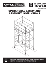
OPERATIONAL
SAFETY AND
ASSEMBLY
INSTRUCTIONS
CONSIGNES
DE SÉCURITÉ ET
INSTRUCTIONS
DE MONTAGE
ACCESS STAIRWAY TOWER
TOUR D’ESCALIER D’ACCÈS
OSHA
CONFORMANCE TO 29 CFR Pt. 1926
EN CONFORMITÉ AVEC 29 CFR Pt. 1926
ANSI
MEETS CODE A10.8
RENCONTRE LA NORME A10.8
CSA
CONFORMITY TO CSA STANDARD
CONFORME À LA NORME CSA
MODELS / MODÈLES :
• M-MATST5713
• M-MATST5719
• M-MATST5726
READ THESE INSTRUCTIONS CAREFULLY BEFORE USING THIS PRODUCT. KEEP THIS MANUAL
HANDY FOR FUTURE REFERENCE.
LIRE SOIGNEUSEMENT CES INSTRUCTIONS AVANT D’UTILISER CE PRODUIT. CONSERVER
CE MANUEL À PORTÉE DE MAIN POUR RÉFÉRENCE ULTÉRIEURE.
Picture may differ from actual product / L’image peut différer du produit réel
1
YEAR WARRANTY
AN DE GARANTIE

METAL CONDUCTS ELECTRICITY
Do not use this equipment where contact may be made with power lines or other live electrical circuits.
OPERATION AND SAFETY
Do not use this equipment if you are in poor health, taking medications, drugs, or have
been consuming alcohol, all of which may impair your ability to work safely on this
product.
All equipment must be inspected before use to ensure the integrity, good repair,and
suitability for intended use.
Inspect before use. Do not use this scaffolding if damaged or parts are missing.
Always use this scaffolding in conformity with local or national legislation
which applies.
A scaffolding must be erected, altered, and dismantled by qualified workers or under
the direct supervision of a qualified person.
The base must be firm and level enough to support the load of scaffolding, workers,
and materials. Sills and base plates are required on soil and unstable ground, or
where any leveling adjustment is needed. The sill must be sound, rigid, and capable of
supporting the maximum loads without settlements or deformation.
Leveling jacks must be adjusted within the limits specified by local regulation.
Frames must be plumb, level and spaced to adequately support loads.
Always install inner and outer handrails to the stair before using the stairway.
Superior adaptable handrail post MUST be secured at the correct compatibility position
to the handrail with bolts.
All handrails MUST be secured to the stair with bolts or locking pins before
using the stairway.
ALWAYS secure both ends of the stair to the scaffolding structure with bolts (TOP and
BASE) to prevent lifting of the stairway.
To prevent the scaffolding from overturning, scaffolding MUST be tied to a building or
structure using wall attachments or guyed when built above the 3:1 ratio. Guying or
tying a scaffolding may require the direction of a professional engineer.
Wall attachments MUST be used to ensure stability for heights exceeding the 3:1 ratio.
Wall attachment must be installed at every 15 ft in height and every 21 ft in length of
the scaffolding structure.
All workers MUST be protected from falls by guardrails or a personal fall arrest system
when working at 10 ft from ground or more.
Guardrails must be installed on all open sides of the platform where a person could
fall a distance of 10 ft. or more. The top rail must be placed 40-44 in. above the work
surface. An intermediate rail must be placed halfway between the top rail and the work
surface. DO NOT STAND ON OR PLACE LOADS ON GUARDRAILS.
STAIRWAY CAPACITY
Uniformly distributed load: 800 lb (363 kg)
Point load applied at the center of any stair tread: 495 lb (225 kg)
SAFETY FACTOR 3:1
FAILURE TO UNDERSTAND AND FOLLOW ALL SAFETY RULES
AND ASSEMBLY INSTRUCTIONS COULD RESULT IN SERIOUS
INJURY OR DEATH.
WARNING
1
Work Planning
1) Evaluate the position of the stairway based on access, soil capacity and
possible anchor points;
2) Depending on the local or national legislation, an installation plan sealed
by a professional engineer may be required;
3) Forming a team of at least three competent workers able to assembly a
scaffolding; (1 equipment provider & 2 assemblers).
2
Protective Equipment
Workers MUST always wear their equipment on a construction site.
1) Protective helmet, safety boots, protective goggles & gloves;
2) Full safety harness complying to local regulations;
3) Life line & anchor points complying to local regulations;
3
Preparation before assembly
1) Secure the work environment with ribbons or job site fence
to limit access.
2) Install vertical lifelines, one per worker.
3) Ensure that the equipment does not fall when properly installed.
4
Assembly
1) Place the sills (planks) on the ground to distribute the loads.
2) Install four leveling jacks on the planks and adjust the level
to compensate irregularities of the soil.
3) Install the stair starting tube on two of the leveling jacks
(starting point of the stairway).
4) Install the first arch frame on the starting tube.
5) Install two cross braces to the first arch frame.
6) Install the second arch frame on the other leveling jacks, connect it to
the cross braces.
7) Adjust the levels, nail the jacks to the planks placed on the ground,
check the perpendicularity of the base.
8) Install the service platforms (not included) at every story on the top
horizontal tube of the arch frames.
9) Install the next two arch frames to the lower frames using coupling pins
and pigtail locks.
10) Connect the two arch frames with cross braces.
11) Repeat steps until the final installation of the access tower to the desired
height.
12) Always Install wall attachments every 15 ft in height (3:1 ratio).
13) Install lifting system at the top of the access tower; hoist post, gin block
pulley and lifting cable.
14) Bring up the stairs starting at the top of the tower.
15) Finish the installation with the stairs at the bottom.
16) Secure both ends of the stair units to the scaffolding structure with bolts
(top and base).
17) Install inner and outer handrails to the stairs, secure it to the stairs using
bolts or locking pins.
18) Install adjustable end-stop guardrail to every arch frame at the upper
point of a stair unit (one by story).
19) At the top of the access tower install the guardrail system.
20) Secure the guardrail and deck installation by making sure there is no fall risk
at the top level. Refer with local or national legislation which applies.
21)
Disassemble the access stairway tower in reverse order.
ASSEMBLY PROCEDURES

LE MÉTAL EST CONDUCTEUR D’ÉLECTRICITÉ
Ne pas utiliser cet équipement où il pourrait entrer en contact avec une ligne électrique ou une source de courant
CONSIGNES ET SÉCURITÉ
Ne pas utiliser cet équipement si vous êtes en mauvaise santé, si vous prenez des
médicaments, ou êtes sous l’emprise de la drogue ou de l’alcool, cela pourrait nuire à
votre capacité à travailler en toute sécurité sur ce produit.
Tout équipement doit être inspecté avant utilisation pour s’assurer de son bon fonctionnement,
de l’intégrité de toutes ses composantes et qu’il est approprié aux besoins requis.
Inspecter avant utilisation. Ne pas utiliser l’échafaudage s’il est endommagé ou s’il
manque des pièces.
Toujours se conformer à la législation locale ou nationale qui s’applique pour l’utilisation
de ce type d’échafaudage.
Un échafaudage doit être érigé, modifié et démonté par des travailleurs qualifiés ou sous
la supervision d’une personne qualifiée.
La base doit être ferme et de niveau pour supporter la charge de l’échafaudage, les
travailleurs et le matériel de travail. Les assises et vérins à vis sont requis sur tout sol ou
condition de sol instable ou lorsque des ajustements de niveau sont requis. Les assises
doivent être en bon état, rigides, et en mesure de supporter la charge maximale sans
affaissement ou déformation.
Les vérins à vis doivent être ajustés dans les limites spécifiées par la réglementation locale.
Les cadres doivent être à la verticale, de niveau et espacés adéquatement pour supporter
les charges.
Toujours installer les rampes intérieures et extérieures à l’escalier avant d’utiliser l’escalier.
Le poteau ajustable supérieur de la rampe DOIT être fixé à la rampe en position correcte
de compatibilité avec des boulons.
Toutes les rampes DOIVENT être fixées à l’escalier à l’aide de boulons ou des goupilles de
verrouillage avant d’utiliser l’escalier.
TOUJOURS fixer les deux extrémités de l’escalier à la structure d’échafaudage à l’aide de
boulons (HAUT et BAS) pour éviter le soulèvement de l’escalier.
Pour éviter que l’échafaudage ne se renverse, l’échafaudage DOIT être sécurisé à une
structure ou à un bâtiment à l’aide d’attaches de mur ou haubané lorsqu’il est construit
au-delà du ratio de 3:1. Haubaner ou attacher un échafaudage peut exiger la direction
d’un ingénieur professionnel.
Les attaches de mur DOIVENT être utilisées pour assurer la stabilité pour des hauteurs
dépassant le ratio 3:1. Les attaches de mur doivent être installées à la structure
d’échaudage à tous les 15 pi de haut et à tous les 21 pi de longueur.
Tous les travailleurs DOIVENT être protégés contre les chutes par des garde-corps ou un
système antichute personnel lorsqu’ils travaillent à 10 pi du sol ou plus.
Les garde-corps doivent être installés sur tous les côtés ouverts de l’aire de travail où une
personne pourrait tomber d’une hauteur de plus de 10 pi. Le garde-corps du haut doit
être installé à 40-44 po au-dessus du niveau de l’aire de travail. Une barre intermédiaire
doit être placée à mi-chemin entre la barre du haut et la plate-forme. NE PAS SE TENIR
SUR LES GARDE-CORPS ET NE PAS Y PLACER DE CHARGE.
CAPACITÉ DE L’ESCALIER
Charge uniformément répartie: 800 lb (363 kg)
Charge ponctuelle appliquée au centre de toute marche d’escalier: 495 lb (225 kg)
FACTEUR DE
SÉCURITÉ 3:1
LA NON-COMPRÉHENSION ET LE NON-RESPECT DE TOUTES LES RÈGLES
DE SÉCURITÉ ET DE TOUTES LES CONSIGNES D’ASSEMBLAGE PEUVENT
ENTRAÎNER DES BLESSURES GRAVES OU MORTELLES.
AVERTISSEMENT
1
Planification du travail
1) Évaluer la position de l’escalier en fonction de l’accès, de la capacité du sol
et des points d’ancrage possibles;
2) En fonction de la législation locale ou nationale, un plan d’installation avec
le sceau d’un ingénieur peut être requis;
3) Former une équipe d’au moins trois ouvriers compétents capables d’assembler un
échafaudage; (1 ravitailleur d’équipement et 2 assembleurs).
2
Équipement de protection
Les travailleurs DOIVENT toujours porter leur équipement sur un chantier
de construction.
1) Casque de protection, bottes de sécurité, lunettes de protection et gants;
2) Harnais de sécurité complet conforme à la réglementation locale;
3) Ligne de vie et points d’ancrage conformes aux réglementations locales;
3
Préparation avant l’assemblage
1) Sécuriser la zone de travail avec des rubans ou une clôture de chantier pour
en limiter l’accès.
2) Installer des lignes de vie verticales, une par travailleur.
3) Assurez-vous que l’équipement ne tombe pas lorsqu’il est correctement installé.
4
Assemblage
1) Placer les seuils (madriers) sur le sol pour répartir les charges.
2) Installer quatre vérins à vis sur les madriers et régler le niveau pour
compenser les irrégularités du sol.
3) Installer la barre de départ d’escalier sur deux des vérins à vis (point de
départ de l’escalier).
4) Installer le premier cadre en arche sur la barre de départ d’escalier.
5) Installer deux croisillons sur le premier cadre en arche.
6) Installer le deuxième cadre en arche sur les autres vérins à vis, le connecter
aux croisillons.
7) Régler les niveaux, clouer les vérins sur les madriers posés au sol, vérifier la
perpendicularité de la base.
8) Installer les plateformes de service (non incluses) à chaque étage sur le tube
horizontal supérieur des cadres en arche.
9) Installer les deux cadres en arche suivants sur les cadres inférieurs en
utilisant des goupilles d’accouplement et verrous queue de cochon.
10) Connecter les deux cadres en arche avec des croisillons.
11) Répéter les étapes jusqu’à l’installation complète de la tour d’accès à la
hauteur désirée.
12) Toujours installer des attaches de mur à tous les 15 pieds de hauteur (ratio 3:1).
13) Installer un appareil de levage au sommet de la tour d’accès; potence, poulie
et câble de levage.
14) Installer les escaliers en commençant par ceux au sommet de la tour.
15) Terminer l’installation des escaliers avec ceux du bas.
16) Fixer les deux extrémités des unités d’escalier à la structure d’échafaudage
à l’aide de boulons (haut et bas).
17) Installer les rampes intérieures et extérieures dans les escaliers, les fixer aux
escaliers en utilisant des boulons ou des goupilles de verrouillage.
18) Installer un garde-corps d’extrémité extensible sur chaque cadre en arche au
point supérieur d’une unité d’escalier (un par étage).
19) Au sommet de la tour d’accès, installez le système de garde-corps.
20) Sécuriser l’installation du garde-corps et du pont supérieur en vous assurant
qu’il n’y a pas de risque de chute possible. Se référer à la législation locale
ou nationale applicable.
21) Démonter la tour d’escalier d’accès dans l’ordre inverse.
PROCÉDURES DE MONTAGE

IN-MATST57-NA-CA01
Metaltech is a registered trademark of Metaltech-Omega inc.
Metaltech est une marque déposée de Metaltech-Omega inc.
CONÇU AU CANADA / FABRIQUÉ EN CHINE
DESIGNED IN CANADA / MADE IN CHINA
WWW.METALTECH.CO
1 800 363-7587
LAVAL, QUEBEC, CANADA H7L 3N6
Service à la clientèle: 1 800 363-7587
Notre personnel du service à la clientèle est disponible pour vous assister. Que ce soit pour vous aider à assembler ce produit, pour signaler une
pièce manquante ou endommagée, ou pour toute autre information à propos de ce produit, veuillez composer notre numéro sans frais.
CONSERVER CE MANUEL POUR RÉFÉRENCE ULTÉRIEURE
Garder ce manuel et la facture d’achat originale dans un endroit sec et sûr pour référence ultérieure.
Customer Service: 1 800 363-7587
Our customer service staff is available to help you. For help with product assembly, to report damaged or missing parts, or for any other information about
this product, please call our toll-free number.
KEEP THIS MANUAL FOR FUTURE REFERENCE
Keep this manual and the original sales invoice in a safe, dry place for future reference.
Garantie limitée de 1 an
Metaltech-Omega inc. garantit ce produit contre toute défectuosité matérielle ou de fabrication. Retourner ce produit à Metaltech-Omega inc. port payé.
Metaltech-Omega inc. s’engage à réparer ou à remplacer, à sa discrétion, ce produit gratuitement et vous le retourner dans un délai raisonnable. Cette
garantie ne couvre pas les dommages causés par un entretien incorrect ou inadéquat ou un usage abusif. Une preuve d’achat doit accompagner le retour.
One Year Limited Warranty
Metaltech-Omega Inc. guarantees this product against any material defect. Please return this product, freight prepaid, to Metaltech-Omega Inc. At its own
discretion, Metaltech-Omega Inc. will replace or repair this product and return it within a reasonable time. This warranty does not cover any damage(s)
caused by any incorrect or inappropriate use, care or maintenance. Proof of purchase must accompany the return.
/

