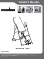
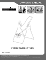
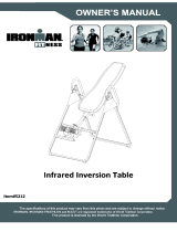
Ironman 5800 Owner's manual
- Type
- Owner's manual
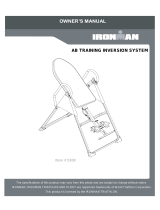
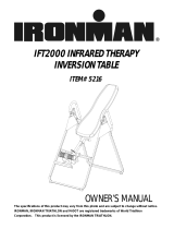
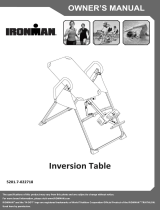
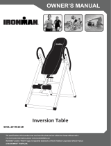
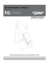
Ironman 5800 inversion table is a personal fitness companion for relieving tension and promoting relaxation by inverting the user, helping to decompress the spine and improve circulation. It features adjustable height settings to accommodate various user heights, and its sturdy construction supports a maximum weight capacity of 350 lbs. The table's comfortable foam bed and secure ankle holders ensure a safe and stable inversion experience.
Ironman 5800 inversion table is a personal fitness companion for relieving tension and promoting relaxation by inverting the user, helping to decompress the spine and improve circulation. It features adjustable height settings to accommodate various user heights, and its sturdy construction supports a maximum weight capacity of 350 lbs. The table's comfortable foam bed and secure ankle holders ensure a safe and stable inversion experience.


-
 1
1
-
 2
2
-
 3
3
-
 4
4
-
 5
5
-
 6
6
-
 7
7
-
 8
8
-
 9
9
-
 10
10
-
 11
11
-
 12
12
-
 13
13
-
 14
14
-
 15
15
-
 16
16
-
 17
17
-
 18
18
-
 19
19
-
 20
20
-
 21
21
-
 22
22
-
 23
23
-
 24
24


Ironman 5800 Owner's manual
- Type
- Owner's manual
Ironman 5800 inversion table is a personal fitness companion for relieving tension and promoting relaxation by inverting the user, helping to decompress the spine and improve circulation. It features adjustable height settings to accommodate various user heights, and its sturdy construction supports a maximum weight capacity of 350 lbs. The table's comfortable foam bed and secure ankle holders ensure a safe and stable inversion experience.
Ask a question and I''ll find the answer in the document
Finding information in a document is now easier with AI
Related papers


Other documents
-
Fitness Reality 2500 Owner's manual
-
LifeGear 75164 Owner's manual
-
-
Ironman Fitness 6571 Owner's manual
-
Exerpeutic 4575 Owner's manual
-
-
-
 Fitness Gear 5226 Owner's manual
-
-
Paradigm 5203 Owner's manual
