Liebherr HC 1580 30 Inch Panel Ready Counter Depth Bottom Freezer Refrigerator User manual
- Category
- Fridges
- Type
- User manual

Home » LIEBHERR » LIEBHERR HC 1580 30 Inch Panel Ready Counter Depth Bottom Freezer Refrigerator
Instruction Manual
Installation Instructions
HC 1580 / HC1581
7084 999-00
For Fully Integrated No Frost
Combined Refrigerator-Freezers
LIEBHERR HC 1580 30 Inch Panel Ready Counter Depth
Bottom Freezer Refrigerator Instruction Manual
Manuals+ — User Manuals Simplified.

Contents
1 HC 1580 30 Inch Panel Ready Counter Depth Bottom Freezer
Refrigerator
2 Important Safety Information
3 R600a Refrigerant
4 Electrical Safety
5 Blocking for Safety
6 Safety Instructions and Warnings
7 Connection to the Water Supply
8 Installation
9 Mounting the Ventilation Grille
10 Mounting the Refrigerator Door Panel
11 Documents / Resources
11.1 References
12 Related Posts
HC 1580 30 Inch Panel Ready Counter Depth Bottom Freezer Refrigerator
IMPORTANT
All types and models are subject to continuous improvement. The manufacturer reserves the right to make
modifications to the shape, equipment, and technology.
Please Read and Follow these Instructions
These instructions contain Danger, Warning, and Caution notes.
This information is important for safe and efficient installation and operation.
Always read and comply with all Danger, Warning, and Caution notes!
DANGER!
Danger indicates a hazard which will cause serious injury or death if precautions are not followed.
WARNING!
Warning indicates a potentially hazardous situation which, if not avoided, could result in death or serious injury.
CAUTION!
Caution indicates a potentially hazardous situation which, if not avoided, may result in minor or moderate injury.
IMPORTANT
This indicates information that is especially relevant to a problem-free installation and operation.
Note to the Installer
It is very important to follow the instructions in the manual to ensure proper installation and operation of the unit.
Before installing the unit, be sure to thoroughly read and understand all of the information in this manual.
WARNING!
Electrocution hazard.
Do not connect to the electrical outlet before the installation is completed.
Important Safety Information
WARNING: Keep ventilation openings, in the appliance enclosure or in the built-in structure, clear of
obstruction.
WARNING: Do not use mechanical devices or other means to accelerate the defrosting process, other than
those recommended by the manufacturer.
WARNING: Do not damage the refrigerant circuit.
WARNING: The power cord must not be damaged while installing the appliance.
WARNING: Multi-sockets or distributor strips and other electronic devices (such as halogen transformers) must

not be positioned and operated at the rear of appliances.
WARNING: Danger of injury through electric shock! There are live parts under the cover. Only have the interior
LED light replaced or repaired by customer service staff or trained personnel.
WARNING: Risk of injury from the LED lamp. The light intensity of the LED light complies with risk group RG 2.
If the cover is defective, do not look directly at the light through optical lenses from close distance. This may
damage your eyes.
WARNING: This appliance must be secured as described in the Use and Care Manual (Installation
Instructions) to rule out any potential risks due to its instability.
WARNING: Do not use electrical appliances inside the food storage compartments of the appliance, unless
they are of the type recommended by the manufacturer.
Any repairs and work on the appliance should only be performed by the customer service department.
Unauthorized work may be dangerous to the user. The power source cable should only be changed or
replaced by the customer service department. Component parts and power cords shall be replaced with like
components performed by factory authorized service personnel only.
Do not stand on the toe kick, drawers or doors or use them to support anything else.
This appliance is not intended for use by persons (including children) with reduced physical, sensory or mental
capabilities or lack of experience and knowledge unless they have been given initial supervision or instruction
concerning use of the appliance by a person responsible for their safety. Children should be supervised to
ensure that they do not play with the appliance.
Do not store explosive substances such as aerosol cans with a flammable propellant in this appliance.
To prevent injury and damage to property, the appliance should only be installed by 4 people.
Check the appliance for signs of damage after unpacking. Contact the supplier if it is damaged. Do not connect
the appliance to the mains power supply.
Avoid prolonged skin contact with cold sur- faces (e.g., chilled/frozen products). If necessary, take safety action
(e.g., gloves).
Do not consume food which has been stored for too long; it could cause food poisoning.
Any repairs and work on the appliance should only be performed by the customer service department or other
trained personnel. The same applies to changing the power cord.
Only perform repair and other work on the appliance when the plug has visibly been disconnected.
Only install, connect, and dispose of the appliance as described in this Use and Care Manual.
In the event of a fault, pull out the plug or switch off the fuse.
When disconnecting the appliance from the power source, pull it out by the plug, never pull on the cable.
If you have a lockable appliance, do not keep the key near the appliance or within reach of children.
The appliance is designed for use in enclosed rooms. Do not operate the appliance outdoors or in areas where
there is moisture or splashing water.
Do not use the interior LED light to light the room. The interior LED light is only designed to illuminate the
interior of the appliance.
Do not allow naked flames or ignition sources to enter the appliance.
Alcoholic drinks or other vessels containing alcohol should be sealed tightly for storage.
R600a Refrigerant
WARNING!

The refrigerant R600a contained within the appliance is environmentally friendly, but flammable. Leaking
refrigerant can ignite. Disposal of Old Appliance
WARNING!
Risk of child entrapment.
Child entrapment and suffocation are not problems of the past.
Junked or abandoned refrigerators are still dangerous even if they will sit for “just a few days.”
If you are getting rid of your old refrigerator, please follow these instructions to help prevent accidents.
Before you discard old appliances:
Take off the doors.
Leave the shelves in place so that children may not easily climb inside.
Cut off the power cord from the discarded appliance. Discard separately from the appliance.
Be sure to follow your local requirements for disposal of appliances.
Contact the trash collection agency in your area for additional information.
Disposal of Packaging Material
WARNING!
Keep packaging materials away from children. Polythene sheets and bags can cause suffocation!
possible, please recycle packaging material at a recycling facility.
Electrical Safety
Connect this appliance to a 15 amp or 20 amp, 110120 VAC circuit which is grounded and protected by a circuit
breaker or fuse.
We recommend using a dedicated circuit for this appliance to prevent circuit overload and the chance of
interruption to the appliance.
This appliance is equipped with a three-prong (grounding) polarized plug for your protection against possible
shock hazards.
Where a two-prong wall receptacle is encountered, contact a qualified electrician and have it replaced with a
properly grounded three-prong receptacle in accordance with all local codes and ordinances.
WARNING!
Electrocution hazard.
Electrical grounding required.
Do not remove the round grounding prong from the plug.
Do not use extension cords or ungrounded (two prong) adapters.
Do not use a power cord that is frayed or damaged.
Do not use a power strip.

Failure to follow these instructions may result in fire, electric shock or death.
Blocking for Safety
WARNING!
To avoid a hazard due to instability of the appliance, it must be fixed in accordance with the instructions.
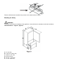
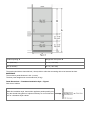
Unit Dimensions – Figure 1, Figure 2
A = 3″ (76 mm)
B = 79-13/16″ (2027 mm)
C = 29-7/8″ (757 mm)
D = 24″ (610 mm)
E = 55 1/4″ (1413 mm)
F = 37-1/8″ (952 mm)

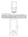
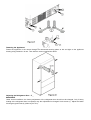
Door Swing Clearance – Figure 3
Please allow for door swing clearance at locations next to a wall.
The illustrated measurement is without mounted front panels. Be sure to add your panel thickness and handle
depth to this measurement in order to avoid interferences.
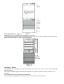
Unit Venting – Figure 4
HCB appliances do not require any ventilation openings in the cabinet. The required air flow is directed through
the toe kick area.
Only use the ventilation grille provided with the appliance. This grille is required for proper operation of the
appliance.
This opening must not be covered with a cabinet base.
Failure to use the supplied grille can result in product failure and will void the warranty.

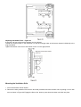
Cabinet Opening Dimensions – Figure 5
Cabinet Height Inset cabinet Depth D Frameless/faceframe cabinet Depth D
80′ 24″ + panel thickness 24′
84′ 24″ + panel thickness 24′

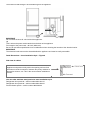
The water line lead-through is at the bottom right of the appliance.
IMPORTANT
Do not install the shut-off valve behind the appliance.
(1)
This is where the power cord extends from the back of the appliance.
Free length of the power cord = 90 inch (2280 mm)
Be sure to take these specifications into consideration when choosing the location of the electrical outlet.
IMPORTANT
The electrical outlet must not be situated behind the appliance and must be easily accessible.
Panel Dimensions – Inset Installation Style – Figure 6
Side view of cabinet
Appliance and panels sit fully within the opening and are flush
with what could be its own box, between two pantry cabinets or
decorative columns, etc. This is the most common installation s
cenario.
You can order stainless steel panels for inset installation style.
Refrigerator door panel 80″- article number 9900 287-00
Refrigerator door panel 84″- article number 9900 285-00
Freezer drawer panels – article number 9900 283-00

Cabinet opening ARefrigerator door panel B
80″ (2032 mm) 45-1/4″ (1150 mm)
84″ (2134 mm) 49-1/4″ (1251 mm)
The panels should be at least 5/8 inch (16 mm) thick to allow the connecting rails to be fastened to them.
IMPORTANT
The maximum panel thickness is 3/4″ (19 mm).
The door panel weight must not exceed 60 lb (27 kg).
Panel Dimensions – Frameless Installation Style – Figure 7
Side view of cabinet
With this installation style, these wider appliance panels partially ove
rlay the shared side gables of adjacent cabinetry so as to mimic the l
ook of a frameless style cabinet.

Cabinet opening C Refrigerator door panel D
80″ (2032 mm) 45-3/4″ (1162 mm)
84″ (2134 mm) 49-3/4″ (1264 mm)
The panels should be at least 5/8 inch (16 mm) thick to allow the connecting rails to be fastened to them.
IMPORTANT
The maximum panel thickness is 3/4″ (19 mm).
The door panel weight must not exceed 60 lb (27 kg).
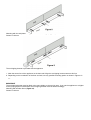
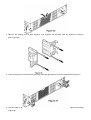
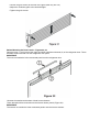
Mounting the Anti Tipping Device – Figures 8 – 11
WARNING!
The anti tipping bracket must be mounted to prevent the appliance from tipping when the fully stocked door is
opened.
Be sure that there is no plumbing or electrical wiring located in this area which screws or drills could damage.
Mounting Options
Mounting the bracket with the wall stud.
Mounting with wall plugs to concrete walls (Figure 8).
Screws 6 x 63 mm

Mounting with the wall plate turning in the screws at an angle ( Figure 9).
Screws 6 x 63 mm
The anti tipping bracket is provided with the appliance.
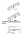
1. Mark the center line of the appliance on the back wall. Align the anti tipping bracket center to this line.
2. Depending on the constitution of the floor and wall, use any possible mounting option as shown in Figures 8 –
11.
IMPORTANT
The anti tipping bracket must be fitted at the same height as the toe kick area. If you set the appliance to a higher
level by laying spacers underneath, the anti tipping bracket must be fitted accordingly.
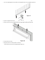
Mounting with wooden floors (Figure 10).
Screws 6 x 63 mm

Mounting with concrete floors using the anchors provided (Figure 11).
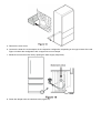
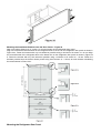
Mounting the Anti Tipping Device in Cabinets deeper than 24″ – Figures 12 – 13
A proper function of the anti tipping bracket is warranted within a cabinet depth of between 24″ and 25″. If the
cabinet is deeper than 25″, a wooden spacer must be mounted between appliance and wall.
WARNING!
Be sure the wooden spacer is fastened securely to the floor.
Measuring for mounting the wooden spacer on inset kitchen cabinets – Figure 12
Measuring for mounting the wooden spacer on frameless kitchen cabinets – Figure 13

IMPORTANT
If the floor slopes down sideways, the anti tipping bracket must be fitted horizontally. Lay down spacers in the
appropriate positions.
Cover Strips – Figure 14
Apply cover strips above, between and below the securing plates on the side walls of the appliance.
Cut the cover strips to the length shown in Figure 14.
Fit the adhesive cover strips leaving a gap of 1/4″ to each securing plate. This ensures problem-free fitting of the
covers.
Safety Instructions and Warnings
Do not install the water connection while the combined refrigerator-freezer is connected to an electrical outlet.
The connection to the water supply may only be made by a trained and licensed plumber.
All equipment and devices used to supply the water to the appliance must comply with the current regulations
for your geographical area.
WARNING!
Connect to potable water supply only.
Water Connection Requirements

The water supply pressure requirements are different based on whether or not the supplied Liebherr water filter
is installed.
With the filter installed, the pressure must be in the range of 40-90 psi (2.8-6.2 bar).
Without the filter installed, the acceptable pressure range is 22-87 psi (1.5-6 bar).
Failure to meet these requirements will likely result in ice maker malfunction and possibly cause a water
leakage that can damage flooring and surrounding furniture.
A shut-off valve, must be installed between the hose line and the main water supply so the water supply can be
stopped if necessary.
IMPORTANT
Do not install the shut-off valve behind the appliance.
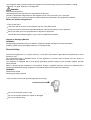
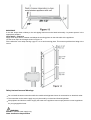
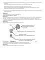
Water Connection Adapter – Figure 15
IMPORTANT
Only use the supplied adapter for connection to the solenoid valve. The solenoid valve has a metric R3/4 male
connector. Any attempt to use other adapters for connection could damage the thread on the solenoid valve.
The supplied adapter enables different connection options for different kinds of water lines. A water line is not
supplied with the appliance.
IMPORTANT
Do not use any old or already remounted water supply lines.
The connection to the valve connector can be done with or without the angle connector, as required.
Braided style ice maker hoses can be connected directly to the threaded ends.
For connection with 1/4″ OD copper lines, use the union nut with compression ring.
IMPORTANT
Make sure that the connection is fitted with a seal and is tight.

Insert the water strainer supplied into the valve connector (Figure 16).
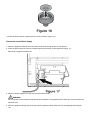
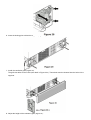
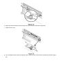
Connection to the Water Supply
1. Move the appliance towards the final position and leave enough space to work behind.
2. Insert the water supply line into its intended opening at the back of the appliance (Figure 17).
Back view of appliance bottom left
3. Move the power supply line to the area of the electrical outlet.
WARNING!
Do not connect to the electrical outlet before the installation is completed and the water line is connected to the
solenoid valve.
4. Move the appliance slowly into the recess until the appliance back slides into the anti tipping bracket (Figure
18).

5. Remove the cover from the solenoid valve (Figure 19).
6. Connect the water line to the adapter in the respective configuration, depending on the type of water line used.
Figure 19 shows the configuration with a copper line as an example.
7. Bleed the air from the water line by opening the water supply temporarily.
8. Screw the adapter onto the solenoid valve (Figure 20).

9. Open the shut-off valve for the water supply and check the entire water system for leaks.
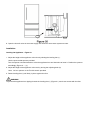
Installation
Leveling the Appliance – Figure 21
1. Adjust the height of the appliance at the front by twisting the leveling feet (1).
Use the open-ended spanner provided.
Turn the spanner counterclockwise to raise the appliance front and clockwise to lower it. Position the spanner
accordingly (Figure 21 – (1)).
2. Adjust the height of the appliance at the rear by turning the adjusting bolts (2).
Use a 1/4″ box spanner or the Torx 25 wrench provided.
3. Rotate leveling feet (1)until firmly in place against the floor.
WARNING!
To prevent the appliance from tipping forward the leveling feet (1) (Figure 21) must have contact with the floor.

Fastening the Appliance in the Recess – Figure 22
Fasten the appliance in the recess through the remounted securing plates at left and right on the appliance
housing using screws 4x 16 mm. Then click the covers supplied into place.
Adjusting the Refrigerator Door – Figure 23
IMPORTANT
Under normal conditions, the factory adjustment of the refrigerator door should not be changed. Only if heavy
loading of the refrigerator door is expected, may the adjustment be changed. Undo screws (1). Adjust the lateral
tilt using the grub screw (2) (Allen key A/F 2.5).

Adjusting the Drawer Front – Figure 24
If required, the front of the freezer drawers can be adjusted.
Transfer the screws shown in the illustration (on the left and right sides of the freezer drawer) individually to the
long slots below.
Tighten the screws in the front of the drawer once it is in the right position.
Mounting the Ventilation Grille
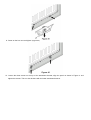
1. Pull out the bottom freezer drawer.
2. Remove the blue protection film from the dust filter provided and insert the filter into its opening in the to kick
area as shown in Figure 25. Engage the filter at the bottom, press down the button and click into place.

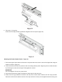
3. Remove the locking pins of both supports. The supports are provided with the appliance accessory
pack (Figure 26).
4. Insert the supports for the ventilation grille on the left and right sides in the motor compartment (Figure 27).
5. The front edge of the brackets is flush with the front of the ventilation grille. Adjust the supports accordingly
(Figure 28).
Page is loading ...
Page is loading ...
Page is loading ...
Page is loading ...
Page is loading ...
Page is loading ...
Page is loading ...
Page is loading ...
Page is loading ...
-
 1
1
-
 2
2
-
 3
3
-
 4
4
-
 5
5
-
 6
6
-
 7
7
-
 8
8
-
 9
9
-
 10
10
-
 11
11
-
 12
12
-
 13
13
-
 14
14
-
 15
15
-
 16
16
-
 17
17
-
 18
18
-
 19
19
-
 20
20
-
 21
21
-
 22
22
-
 23
23
-
 24
24
-
 25
25
-
 26
26
-
 27
27
-
 28
28
-
 29
29


Liebherr HC 1580 30 Inch Panel Ready Counter Depth Bottom Freezer Refrigerator User manual
- Category
- Fridges
- Type
- User manual
Ask a question and I''ll find the answer in the document
Finding information in a document is now easier with AI
Related papers
-
Liebherr HCB 1590 User manual
-
Liebherr CBS-2092 Installation guide
-
-
Faber HCB1580 Installation guide
-
Liebherr HCB-1590 User manual
-
-
-
Liebherr HC1551 Installation guide
-
-