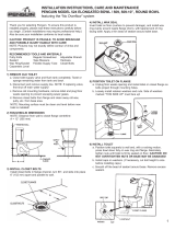
Fluidmaster K-7530-5000 Installation guide

Category
Sanitary ware
Type
Installation guide

Fluidmaster K-7530-5000 is a toilet installation kit that provides everything you need to install a new toilet or replace an old one. It includes Better Than Wax™ rubber seal, SetFast™ bolts, and Secure Cap™. The rubber seal creates a watertight seal between the toilet and the floor, while the SetFast™ bolts make installation quick and easy. The Secure Cap™ provides a secure connection between the toilet and the floor, preventing leaks.

Fluidmaster K-7530-5000 is a toilet installation kit that provides everything you need to install a new toilet or replace an old one. It includes Better Than Wax™ rubber seal, SetFast™ bolts, and Secure Cap™. The rubber seal creates a watertight seal between the toilet and the floor, while the SetFast™ bolts make installation quick and easy. The Secure Cap™ provides a secure connection between the toilet and the floor, preventing leaks.

INSTALL WITH CONFIDENCE
QUICK Install Guide
K-7530-5000
TOILET INSTALL KIT
*See back page for important product warnings and warranty information
HOW-TO VIDEO
VIDEO
VISIT: FLUIDMASTER.COM
K-7530-5000 PRODUCT PAGE
SPANISH - Page 14
2 3
STEP 1: REMOVE OLD TOILET
GETTING STARTED
A: TURN OFF WATER
B: DRAIN WATER
Flush toilet to drain most of the water from the tank and bowl.
C: REMOVE CONNECTOR
Remove water supply connector from
bottom of fill valve and from the wall.
FLUSH
PARTS OVERVIEW TOOLS NEEDED
BETTER THAN WAX
SECURE CAP
Rubber Seal
Slide-on Spacer
Bolt hole
Bolt hole
Towel
(Optional)
Putty Knife
(Optional)
Ruler
9/16” Socket
Wrench
SETFASTBOLTS
Solid Brass
Stud Bolts (x2)
Lock Washer (x2)
Anchor Nut (x2)
Acorn Nut (x2)
Secure CapTM (x2)
Cap Base (x2)
Anti-Spin
Washer (x2)
Toilet Shims (x2)
Box Cutter
(Optional)
Level
(Optional)
Threaded Adapters
Silver 1/2”, Black 3/8”, Bronze 7/16”
CLICK SEAL® CONNECTOR
20” Toilet Connector
4 5
STEP 2: PLACE SETFAST BOLTS
STEP 1: REMOVE OLD TOILET (CONTINUED)
D: REMOVE TOILET CAPS
Then unscrew hex nuts to release
toilet bowl from the floor.
F: CLEAN BOTTOM OF TOILET
Scrape off wax with putty knife and wipe clean. No wax residue
should remain.
E: REMOVE OLD BOLTS FROM
THE TOILET FLANGE
9/16”
Socket Wrench
Putty Knife
(Optional)
A: SLIDE YELLOW LOCK WASHER
(D) UP.
B: INSTALL BOLT (A) INTO
FLANGE SLOT.
When positioned, pull bolt up and
press down on yellow lock washer
(D) to secure.
NOTE: Pre-assemble SetFast (if needed). Thread stud into anchor nut, 2
or 3 turns only. White Dot, “thread locker”, must be closest to top.
(A) Brass Bolt
(D) Lock Washer
(C) Anchor Nut
(B) Thread Locker (white dot)
6 7
STEP 3: FLANGE HEIGHT
A: DETERMINE FLANGE HEIGHT
Check if flange is above, even with
or below floor. If flange is below the
floor, use ruler to determine flange
depth.
A: REMOVE SPACER FROM SEAL.
Spacer will not be used for above-floor
installs and can be discarded.
B: INSTALL SEAL OVER FLANGE.
Slide seal holes over bolts. Proceed to Step 5.
B: PROCEED TO CORRESPONDING SECTION IN
STEP 4 FOR YOUR FLANGE HEIGHT.
FLANGE ABOVE
FLOOR
FLANGE EVEN WITH
OR UP TO 1/4”
BELOW FLOOR
FLANGE MORE
THAN 1/4”
BELOW FLOOR
STEP 4: FLANGE & SEAL INSTALLATION
FLANGE ABOVE FLOOR RUBBER SEAL INSTALLATION
8 9
STEP 5: TOILET INSTALLATION
STEP 4: FLANGE & SEAL INSTALLATION (CONTINUED)
A: INSTALL TWO SEALS ON TOP
OF SPACER.
Slide spacer holes over bolts. Then
slide each of the seal bolt holes
over bolts. Important: Foam side
of spacer must face down as
pictured or leaks may occur.
Proceed to Step 5.
FLANGE MORE THAN 1/4” BELOW FLOOR INSTALLATION
NOTE: For a flange depth greater than ½” a flange extender is
required. (2nd seal purchased separately)
A: INSTALL SPACER OVER FLANGE.
Slide seal holes over bolts.
Important: Foam side of spacer
must face down as pictured or
leaks may occur.
B: INSTALL SEAL ON TOP OF
SPACER.
Slide bolt holes over bolts.
Proceed to Step 5.
FLANGE EVEN WITH OR UP TO 1/4” BELOW
FLOOR INSTALLATION
A: SET BOWL.
Position toilet bowl over seal, guiding holes in toilet base
over bolts.
NOTE: Toilet can be repositioned on seal, if needed, unlike traditional
wax rings.
NOTE 2: If toilet rocks, do not force by overtightening the bolts. Locate
shims to firmly secure toilet (see next page).
STEP 6: SECURE TOILET
A: INSTALL THREADED CAP BASE
ONTO BOLT, FLAT SIDE DOWN.
B: PLACE ANTI-SPIN WASHER
INSIDE THREADED CAP BASE.
Threaded
Cap Base
Anti-Spin
Washer
11
STEP 6: SECURE TOILET (CONTINUED)
C: THREAD ACORN NUT INTO BOLT.
Tighten until nut engages “thread locker”
dot and it’s snug (bolt will self-adjust
height). Use wrench to tighten an
additional ¼” turn. CAUTION: DO NOT
OVERTIGHTEN. Overtightening can cause
bowl or flange to crack.
NOTE: If toilet rocks, do not force by
overtightening the bolts. Locate shims to
firmly secure toilet (see option below).
D: SCREW SECURE CAP ON THE
THREADED CAP BASE.
Acorn
nut
B: PLACE SHIMS
Gently slide the shim(s) under the toilet with your hand until the
rocking stops. CAUTION: Don’t use tools or force the shims.
This could cause you to lift the toilet, creating extra space that
shouldn’t be there.
C: CUT THE ENDS
Carefully cut the ends of the shims with a knife so that the edges
are not visible.
D: CHECK ACORN NUT
Make sure the acorn nuts are still securely tightened. Retighten
if necessary. CAUTION: DO NOT OVERTIGHTEN. Overtightening can
cause bowl or flange to crack.
(OPTIONAL) Shim toilet if needed
A: PLACE A LEVEL ON THE BOWL
Determine which side of the toilet is sloping.
10
Socket Wrench
12 13
STEP 7: CONNECT SUPPLY LINE
B: THREAD THE METAL NUT ON
CLICK SEAL® CONNECTOR ONTO
THE WATER SUPPLY VALVE.
Tighten ½ turn beyond hand tight.
A: CHOOSE THE CORRECT ADAPTER
Try attaching adapters to the water supply valve then inserting
the adapter thread-side first into the metal nut.
C: GENTLY TURN CLICK SEAL® NUT
CLOCKWISE*
The “click” lets you know it’s sealed!
D: SLOWLY TURN ON WATER AT THE
SHUTOFF VALVE*.
Note: Carefully check for leaks at shutoff
valve. If leak appears, tighten nut just
enough to provide a leak-free joint.
YOU DID IT!
We knew you could!
Share your success story
with friends and family!
#FixedMyToilet
#Fluidmaster
STEP 8: FLUSH THE TOILET
A: FLUSH THE TOILET
If you’re satisfied with the flush, YOU’RE DONE!
* DO NOT OVERTIGHTEN. DO NOT USE TOOLS ON PLASTIC NUT OR PLASTIC FILL VALVE.
Overtightening and/or the use of tools could cause damage and lead to failure of the nut and/or
fill valve. Such damage may not be visible to the eye. Failure of the nut and/or fill valve can lead to
significant water leakage and water damage.
14 15
GUÍA DE INSTALACIÓN RÁPIDA
RESUMEN DE PIEZAS HERRAMIENTAS
BETTER THAN WAX
SECURE CAP
Sello de Caucho
Espaciadora
Deslizable
Agujero para
el perno
Agujero para
el perno
PERNOS SETFAST
Pernos de Latón
Maciso (x2)
Arandela de
Seguridad (x2)
Tuerca de Anclaje (x2)
Tuerca Bellota (x2)
Secure CapTM (x2)
Base de Tapa (x2)
Arandela anti-
fricción (x2)
Cuñas Plásticas (x2)
Toalla
(Opcional)
Espátula para
Masilla
(Opcional)
Regla
Llave de Tubo
(14mm)
Cortador
de Caja
(Opcional)
Nivel
(Opcional)
Adaptadores Roscados
Plateado 1/2”, Negro 3/8”, de Bronce 7/16”
CLICK SEAL®
CONECTOR DE SUMINISTRO DE 20”
PASO 1: PREPARE EL TANQUE (PÁGINAS 3-4)
A: CIERRE EL AGUA.
B: DRENE EL AGUA. Descarga el inodoro para drenar la mayor parte del agua del
tanque y la taza.
C: REMUEVA EL CONECTOR DE SUMINISTRO DE AGUA. Remueva desde la parte
inferior de la válvula de llenado y de la pared.
D: REMUEVA LAS TAPAS DE PERNO. Remueva las tuercas viejas para extraer el
inodoro del suelo.
E: EXTRAIGA LOS PERNOS VIEJOS DE LA BRIDA.
F: LIMPIE LA BRIDA Y LA BASE DEL INODORO. Remueva la cera
raspándola con la espátula y frotando para limpiarla. No deben quedar
restos de cera.
PASO 2: COLOQUE LOS PERNOS SETFAST (PÁGINA 5)
NOTA: Pre-ensemble los pernos SetFast (si es necesario). Enrosque el espárrago en
la tuerca de anclaje, sólo 2 o 3 vueltas. El punto blanco, o “casillero de rosca,”
debe estar más cerca de la parte superior.
A: DESLICE LA ARANDELA DE SEGURIDAD AMARILLA (D) HACIA ARRIBA.
B: COLOQUE LOS PERNOS NUEVOS. Coloque sus cabezas en las ranuras de
la brida. Ya que estén en posición, hale cada perno hacia arriba, y presione la
arandela de seguridad (D) hacia abajo para asegurarla.
(A) Perno de Latón Maciso
(D) Arandela de Seguridad
(C) Tuerca de Anclaje
(B) Punto Blanco “Casillero De Rosca”
Espátula para
Masilla
(Opcional)
16
GUÍA DE INSTALACIÓN RÁPIDA
17
PASO 3: LA ALTURA DE LA BRIDA (PÁGINA 6)
A: DETERMINE LA ALTURA DE LA BRIDA. Establezca si la brida se en-
cuentra por encima, por debajo del suelo o a nivel con este. Si la brida
se encuentra por debajo del suelo, utilice una regla o cinta métrica para
establecer su profundidad.
B: PROCEDA CON EL PASO CORRESPONDIENTE PARA DETERMINAR LA
ALTURA DE LA BRIDA.
PASO 5: INSTALE EL INODORO (PÁGINA 9)
A: COLOQUE EL INODORO SOBRE EL SELLO, con los orificios de guía en la base
del inodoro sobre los pernos.
NOTA: Puede reposicionarse el inodoro sobre el sello, de ser necesario, a
diferencia de los anillos tradicionales de cera.
NOTA 2: Si el inodoro se mece, no lo force ajustando los pernos. Localice las
cuñas de plástico para asegurar la base del inodoro (lea la opción a continuación).
PASO 6: ASEGURE EL INODORO (PÁGINAS 9-10)
PASO 4: COLOCACIÓN DEL SELLO DE CAUCHO (PÁGINAS 7-8)
A: EXTRAIGA LA ARANDELA ESPACIADORA DEL SELLO. La arandela espaciadora
no será utilizada para la instalación por encima del suelo y puede ser desechada.
B: COLOQUE EL SELLO SOBRE LA BRIDA deslizando los orificios para pernos
sobre los pernos. Proceda al Paso 5.
NOTA: Para una profundidad mayor de 1/2” (12,7 mm) se requiere un extensor de
bridas (el segundo sello se vende por separado).
A: COLOQUE LA ESPACIADORA SOBRE LA BRIDA deslizando los orificios para
pernos sobre ellos. IMPORTANTE: El lado de espuma de la espaciadora debe
quedar mirando hacia abajo, como se muestra en la imagen (p.8). De lo
contrario, se generarán fugas. Proceda al Paso 5.
A: COLOQUE LA ESPACIADORA SOBRE LA BRIDA deslizando los orificios para
pernos sobre ellos. IMPORTANTE: El lado de espuma de la espaciadora debe
quedar mirando hacia abajo, como se muestra en la imagen (p.8). De lo con-
trario, se generarán fugas.
B: COLOQUE EL SELLO SOBRE LA ARANDELA ESPACIADORA deslizando los
orificios para pernos sobre ellos. Proceda al Paso 5.
Regla
BRIDA ENCIMA A MÁS DE 1/4”
(6,35mm) DEBAJO
DEL SUELO
A NIVEL O HASTA
1/4” (6,35mm) POR
DEBAJO
BRIDA ENCIMA
A MÁS DE 1/4” (6,35mm) DEBAJO DEL SUELO
A NIVEL O HASTA 1/4” (6,35mm) POR DEBAJO
Base
Enroscada
Arandela
Anti-
Fricción
Tuerca
Bellota
A: INSTALE LA BASE ROSCADA SOBRE EL PERNO, parte
plana hacia abajo.
B: INSERTE LA ARANDELA ANTI-FRICCIÓN dentro de la
base roscada.
D: INSTALE LA TAPA SECURE CAPTM sobre la base roscada.
C: ENROSQUE LA TUERCA BELLOTA SOBRE EL PERNO.
Apriete hasta que la tuerca encaje el punto “casillero de
rosca.” NOTA: Si el inodoro se mece, no lo force ajustando los
pernos. Localice las cuñas de plástico para asegurar la base
del inodoro (lea la opción en la siguiente página).
18 19
GUÍA DE INSTALACIÓN RÁPIDA
A: COLOQUE UN NIVEL SOBRE LA TAZA. Determine qué lado del inodoro
está inclinado.
B: COLOQUE LAS CUÑAS. Deslice suavemente la(s) cuña(s) debajo del
inodoro con la mano hasta que se detenga el balanceo. PRECAUCIÓN: No
use herramientas ni fuerce las cuñas. Esto podría hacer que levante el
inodoro, creando un espacio adicional que no debería estar ahí.
C: CORTE LOS EXTREMOS. Corte con cuidado los extremos de las cuñas
con el cortador de caja para que los bordes no sean visibles.
D: REVISE LA TUERCA BELLOTA. Asegúrese de que las tuercas de bellota
aún estén bien apretadas. Vuelva a apretar si es necesario. PRECAUCIÓN:
NO APRIETE DEMASIADO. Apretar demasiado puede hacer que la taza
o la brida se agrieten.
(OPCIONAL) Use la(s) cuñas plásticas si es necesario (PÁGINAS 10-11)
PASO 7: INSTALE EL CONECTOR DE SUMINISTRO DE AGUA (P.12)
Para asistencia para la instalación, comuníquese
con nuestro departamento de servicio técnico.
EMAIL, CHAT o LLAME
a nuestro número gratuito.
www.fluidmaster.com/support
1-800-631-2011
Horario Disponible:
Lunes – Viernes
5:30 AM - 5:00 PM Hora Estándar del Pacífico
¿PREGUNTAS
ADICIONALES?
* NO APRIETE DEMASIADO. NO USE HERRAMIENTAS CON LA TUERCA DE PLÁSTICO O LA VÁLVULA
DE LLENADO DE PLÁSTICO. Apretar demasiado y/o usar herramientas podría causar daños y provocar
fallas en la tuerca y/o la válvula de llenado. Es posible que dicho daño no sea visible a simple vista. La falla
de la tuerca y/o la válvula de llenado puede provocar una fuga de agua significativa y daños por agua.
A: ELIJA EL ADAPTADOR CORRECTO (DORADO, DE BRONCE O PLATEADO), con
cuidado enrosque éste adaptador en la tuerca de metal del conector.
B: ENROSQUE LA TUERCA DE METAL DEL SUMINISTRO
DE AGUA CLICK SEAL® EN LA VÁLVULA DE CIERRE y
apriete media vuelta más de lo que apretó a mano.
C: ABRA LENTAMENTE EL SUMINISTRO DE AGUA CLICK
SEAL® CON LA LLAVE DE PASO.* (El click le garantiza
que está sellada!)
D: ABRA LENTAMENTE EL SUMINISTRO DE AGUA CON
LA LLAVE DE PASO.* NOTA: Verifique cuidadosamente
si gotea la llave de paso. Si gotea, ajuste las tuercas
sólamente lo suficiente para que no goteen las uniones.
A: DESCARGUE EL SANITARIO.
Si está satisfecho con el descargue, ¡TERMINÓ!
PASO 8: DESCARGUE EL SANITARIO
#FixedMyToilet
#Fluidmaster
¡LO LOGRÓ!
¡Sabíamos que podía!
¡Comparta su historia de éxito con sus amigos y familia!
Nivel
(Opcional)
Cortador
de Caja
WARNING
DO NOT USE IN-TANK DROP-IN TOILET BOWL CLEANERS CONTAINING BLEACH OR CHLORINE. Use of such products will: (1) RESULT IN
DAMAGE to tank components and MAY CAUSE FLOODING and PROPERTY DAMAGE and (2) VOID FLUIDMASTER WARRANTY.
Fluidmaster Flush ‘n Sparkle Toilet Bowl Cleaning System is recommended for those choosing to use in-tank bowl cleaners and WILL NOT
VOID the FLUIDMASTER WARRANTY because it will not damage the components. DO NOT overtighten nuts or tank/bowl may crack. Always
use quality Fluidmaster parts when installing or repairing. Fluidmaster will not be responsible or liable for use of non-Fluidmaster parts
during installation or repair.
LIMITED TEN-YEAR EXPRESS WARRANTY
Subject to the “Exclusions” set forth below, Fluidmaster Inc. promises to the consumer to repair, or at the option of
Fluidmaster Inc. to replace any part of this plumbing product which proves to be defective in workmanship or materials
under normal use for ten years from the date of purchase. All costs of removal, transportation and reinstallation to obtain warranty service
shall be paid by the consumer. During this “Limited Ten Year Express Warranty,” Fluidmaster Inc. will provide, subject to the “Exclusions”
section set forth below, all replacement parts free of charge, necessary to correct such defects. This “Limited Ten Year Warranty” is null and
void if this plumbing product has not been installed and maintained in accordance with all written instructions accompanying the product,
and if non-Fluidmaster Inc. parts are used in installation.
EXCLUSIONS: FLUIDMASTER INC. SHALL NOT BE LIABLE FOR INCIDENTAL OR CONSEQUENTIAL DAMAGES, INCLUDING COSTS OF
INSTALLATION, WATER DAMAGE, PERSONAL INJURY OR FOR ANY DAMAGES RESULTING FROM ABUSE OR MISUSE OF THE PRODUCT, FROM
OVERTIGHTENING OR FROM FAILURE TO INSTALL OR MAINTAIN THIS PLUMBING PRODUCT IN ACCORDANCE WITH THE WRITTEN INSTRUC-
TIONS, INCLUDING USE OF NON-FLUIDMASTER PARTS. DO NOT USE IN-TANK DROP-IN TOILET BOWL CLEANERS CONTAINING BLEACH OR
CHLORINE. USE OF SUCH PRODUCTS WILL RESULT IN DAMAGE TO TANK
COMPONENTS AND MAY CAUSE FLOODING AND PROPERTY DAMAGE. USE OF SUCH PRODUCTS WILL VOID THIS WARRANTY.
ADVERTENCIA
NO UTILICE LIMPIADORES DE TAZA DE INODORO QUE SE COLOQUEN EN EL TANQUE O SE SUMERJAN EN EL INODORO QUE CONTENGAN
CLORO. El uso de este tipo de productos: (1) PRODUCIRÁ DAÑOS en los componentes del tanque, POSIBLES INUNDACIONES, así como
DAÑOS A LA PROPIEDAD y (2) ANULARÁ LA GARANTÍA DE FLUIDMASTER. Se recomienda el sistema de limpieza de taza de inodoro Flush ’n
Sparkle® de Fluidmaster para aquellos usuarios que desean utilizar limpiadores de tazas dentro del tanque SIN ANULAR la GARANTÍA DE
FLUIDMASTER, ya que este sistema no daña los componentes.
NO apriete demasiado las tuercas o el tanque, ya que la taza se puede agrietar. Siempre use piezas de calidad Fluidmaster al instalar o
reparar. Fluidmaster no se hace responsable por el uso de piezas durante la que no sean de Fluidmaster durante la instalación o reparación.
GARANTÍA EXPLÍCITA LIMITADA DE DIEZ AÑOS
Salvo en las “Exclusiones” mencionadas más adelante, Fluidmaster, Inc. se compromete a reparar o, según sea la opción de Fluidmaster,
Inc., reemplazar cualquier pieza de este producto de plomería que presente defectos en los materiales y la mano de obra bajo un uso normal
durante diez años desde la fecha de compra. Todos los costos de retiro, transporte y reinstalación para obtener el servicio de garantía deben
ser cubiertos por el consumidor. Durante esta “Garantía explícita limitada de diez años”, Fluidmaster, Inc. proporcionará, salvo en los casos
mencionados en las “Exclusiones” más adelante, todas las piezas de repuesto sin costo alguno, que sean necesarias para corregir tales
defectos. Esta “Garantía limitada de diez años” quedará nula y sin validez si este producto de plomería no ha sido instalado ni mantenido
de acuerdo con las instrucciones escritas que se incluyen con el producto y en caso de que durante la instalación no se utilicen piezas de
Fluidmaster Inc.
EXCLUSIONES: FLUIDMASTER INC. NO SERÁ RESPONSABLE POR DAÑOS INCIDENTALES O RESULTANTES, INCLUYENDO EL COSTO DE INSTA-
LACIÓN, DAÑOS PRODUCIDOS POR EL AGUA, LESIONES PERSONALES O POR ALGÚN OTRO DAÑO QUE SEA RESULTADO DEL ABUSO O EL MAL
USO DEL PRODUCTO, POR USO EXCESIVO DE FUERZA O POR NO INSTALAR O MANTENER ESTE PRODUCTO DE PLOMERÍA DE ACUERDO CON
LAS INSTRUCCIONES ESCRITAS, LO QUE INCLUYE EL USO DE PIEZAS QUE NO SEAN DE FLUIDMASTER, INC. NO UTILICE LIMPIADORES DE
TAZA DE INODORO QUE SE COLOQUEN EN EL TANQUE O SE SUMERJAN EN EL INODORO QUE CONTENGAN BLANQUEADOR O CLORO. EL USO
DE ESTOS PRODUCTOS PRODUCIRÁ DAÑOS EN LOS COMPONENTES DEL TANQUE, POSIBLES INUNDACIONES Y DAÑOS A LA PROPIEDAD. EL
USO DE ESTOS PRODUCTOS ANULARÁ ESTA GARANTÍA.
30800 Rancho Viejo Road, San Juan Capistrano, CA 92675
www.Fluidmaster.com • 800-631-2011
Contact Fluidmaster for troubleshooting help or visit www.Fluidmaster.com
M-F 5:30 am - 5:00 pm PST.
Comuníquese con Fluidmaster para obtener ayuda para resolver problemas o visite www.fluidmaster.com
De lunes a viernes de 5:30 a.m. a 5:00 p.m. hora estándar del Pacífico.
7-1673 Grev. 1, 3/21
ADDITIONAL QUESTIONS?
For installation assistance, contact our technical services department.
EMAIL, CHAT or CALL our toll-free number.
www.fluidmaster.com/support 1-800-631-2011
Hours Available: Monday – Friday 5:30 AM - 5:00 PM PST
  • Page 1 1
  • Page 2 2
  • Page 3 3
  • Page 4 4
  • Page 5 5
  • Page 6 6
  • Page 7 7
  • Page 8 8
  • Page 9 9
  • Page 10 10
  • Page 11 11

Fluidmaster K-7530-5000 Installation guide

Category
Sanitary ware
Type
Installation guide

Fluidmaster K-7530-5000 is a toilet installation kit that provides everything you need to install a new toilet or replace an old one. It includes Better Than Wax™ rubber seal, SetFast™ bolts, and Secure Cap™. The rubber seal creates a watertight seal between the toilet and the floor, while the SetFast™ bolts make installation quick and easy. The Secure Cap™ provides a secure connection between the toilet and the floor, preventing leaks.

Ask a question and I''ll find the answer in the document

Finding information in a document is now easier with AI

in other languages