Milwaukee 2939-20 User manual

Type
User manual

Milwaukee 2939-20: The compact and powerful braking die grinder for precise metalworking. Its high-performance motor and variable speed control deliver up to 28,000 RPM for fast and efficient material removal. The tool features a compact and ergonomic design for comfortable handling and control, making it ideal for intricate and detailed work in tight spaces. Its FUEL technology provides extended runtime and increased durability, while the slide switch ensures precise speed control. Additionally, the built-in LED light illuminates the work area for enhanced visibility.

Milwaukee 2939-20: The compact and powerful braking die grinder for precise metalworking. Its high-performance motor and variable speed control deliver up to 28,000 RPM for fast and efficient material removal. The tool features a compact and ergonomic design for comfortable handling and control, making it ideal for intricate and detailed work in tight spaces. Its FUEL technology provides extended runtime and increased durability, while the slide switch ensures precise speed control. Additionally, the built-in LED light illuminates the work area for enhanced visibility.

66 30 31 35
36 37 40
1
2
3
4
5
38
60
13
62
30
36
40
28
65
37
33 32 34 35
31
(5)
63 1
2
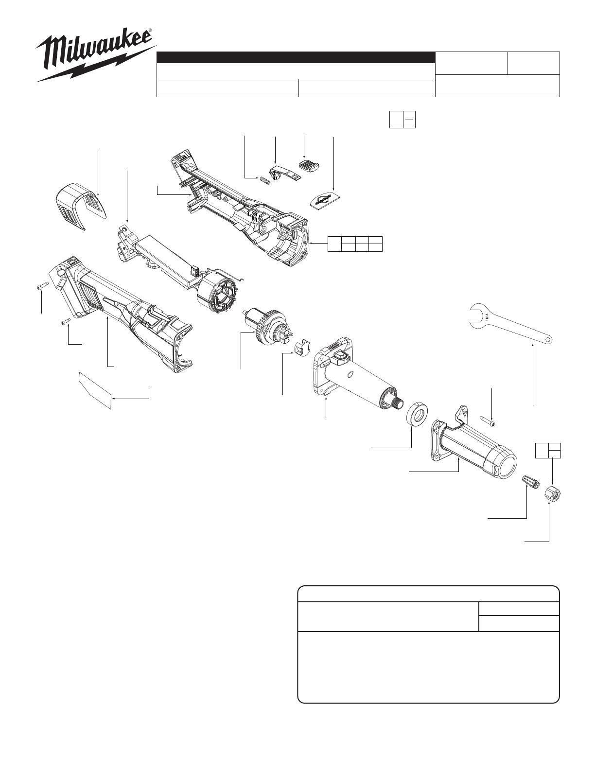
M18 FUEL™ Braking Die Grinder, Slide Switch
2939-20 N43A
54-22-2710
Dec. 2022
REVISED BULLETIN
SERVICE PARTS LIST
BULLETIN NO.
WIRING INSTRUCTION
DATE
SPECIFY CATALOG NO. AND SERIAL NO. WHEN ORDERING PARTS
CATALOG NO. STARTING
SERIAL NO.
EXAMPLE:
Component Parts (Small #) Are Included
When Ordering The Assembly (Large #).
0
00
MILWAUKEE TOOL l www.milwaukeetool.com
13135 W. LISBON RD., BROOKFIELD, WI 53005
Drwg. 2
FIG. PART NO. DESCRIPTION OF PART NO. REQ.
1 --------------- Collet Nut 1
2 --------------- Collet 1
3 05-88-1255 St Screw M3.5x16MM PH B 4
4 31-15-0272 Spindle Housing Cover 1
5 22-80-0041 LED Holder 1
13 42-90-0024 Coupler 1
28 31-15-0103 Dust Cover 1
36 --------------- St Screw M2.6x0.907 FH Phillips 2
30 06-82-1087 St Screw M3.0x1.058 PH Torx T10 B 1
31 06-82-2025 St Screw M3.5x16MM PH B Torx 5
32 31-92-0286 Slide Pole 1
33 40-50-0243 Spring 1
34 42-42-0147 Lock-On Button 1
35 43-84-0207 Rapid Stop Plate 1
36 --------------- Handle Housing Cover 1
37 --------------- Handle Housing Support 1
38 49-96-4090 11/16" Open End Wrench 1
39 44-68-0027 Rubber Plug 1
40 12-20-0587 Service Nameplate 1
60 28-50-0113 Spindle Housing Assembly 1
62 16-01-0071 Rotor Assembly 1
63 44-40-0091 Collet Nut Assembly 1
65 14-20-0400 Electronic Assembly 1
66 14-38-0326 Housing Kit 1
SEAT TORQUE
FIG. PART NO. WHERE USED (kgf-cm) (lb-in)
3 --------------- St Screw M3.5x16MM 16-20 6.1-17.3
19 --------------- Taptite Screw M3.5x0.6 T10S 15-18 13-15.6
25 --------------- Taptite Screw M2.3x0.907 T8 5-6 4.3-5.2
36 --------------- Taptite Screw M2.6x0.907 Philips 4-5 3.4-4.3
40 --------------- Taptite Screw M3.0x1.058 T10 3.5-4.5 3-3.9
41 --------------- Taptite Screw M3.5x16MM T10 12.5-15.5 10.8-4.3
SCREW TORQUE SPECIFICATIONS
SEE PAGE 2
= WIRE TRAPS
or GUIDES
Terminal
Block
Fuse
Control
Board
Motor
SERVICE WIRING
Terminals, Connectors and 1 or 2 End Wire Preparation
Wire
Color
Wire
No. Length
WIRING SPECIFICATIONS
1 Black 74 +4/-0 Connect with Motor and Control Board
2 Red 89 +4/-0 Connect with Motor and Control Board
3 White 104 +4/-0 Connect with Motor and Control Board
4 Red 55 +4/-0 Connect with Fuse and Control Board
5 Black 70 +4/-0 Connect with Terminal Block and Control Board
6 Red 40 +4/-0 Connect with Terminal Block and Fuse
Install the electronics assembly as shown.
Route wires around screw bosses and into wire
traps. Be sure all components are seated squarely
and rmly in place. Be sure there is no interference
when installing the housing cover (36).
Ground Terminal
Prior to installing the electronics assembly (65) into the housing
support (37), place grounding terminal over screw boss as shown.
Route ground wire, removing as much slack as possible. Be sure
wire is pressed rmly to the back of the wire traps.
Wire Traps
For the sake of clarity, the white wire is
represented in gold color in the diagram.
  • Page 1 1
  • Page 2 2

Milwaukee 2939-20 User manual

Type
User manual

Milwaukee 2939-20: The compact and powerful braking die grinder for precise metalworking. Its high-performance motor and variable speed control deliver up to 28,000 RPM for fast and efficient material removal. The tool features a compact and ergonomic design for comfortable handling and control, making it ideal for intricate and detailed work in tight spaces. Its FUEL technology provides extended runtime and increased durability, while the slide switch ensures precise speed control. Additionally, the built-in LED light illuminates the work area for enhanced visibility.

Ask a question and I''ll find the answer in the document

Finding information in a document is now easier with AI