1 Hearth & Home Technologies • IFT-ACM Installation Instructions • 2326-988 • 9/16
Leave this manual with party responsible for use
and operation.
IFT-ACM
IntelliFire™ Touch Auxiliary Control Module
Installation Instructions
1. Introduction
The IntelliFire™ Touch auxiliary control module (IFT-
ACM) is an AC powered device that controls peripheral
devices such as lights, fans and Power Vents approved
for use in Hearth & Home Technologies products that are
equipped with Intellire™ Touch technology. It is con-
nected to and controlled by the Intellire™ Touch Elec-
tronic Control Module (IFT-ECM).
2. IFT-ACM Installation
A. Precautions
This device is tested and safe when installed in accor-
dance with this installation manual. Do not install any
components that may be damaged.
Do not modify, disassemble, or substitute any of the com-
ponents included with this kit. Installation of this unit must
be done by a qualied service technician.
The location of this device may affect performance. An
assessment of the location should be done prior to instal-
lation for optimum performance.
Hearth & Home Technologies disclaims any responsibility
for, and the warranty will be voided by, the following actions:
• Installation and use of any damaged system component.
• Modication of the system component.
• Installation other than as instructed by Hearth & Home
Technologies.
• Installation and/or use of any component part not approved
by Hearth & Home Technologies.
Any such action may cause a re hazard.
• Read, understand and follow these instructions for safe
installation and operation.
B. Determine Location
The IFT-ACM latches to the IntelliFire™ Touch elec-
tronic control module (IFT-ECM). Remove any material
or objects in the immediate vicinity of the vents on the
IFT-ACM. These vents allow the IFT-ACM to dissipate
excess heat into the air.
The IFT-ACM is approved for interior installation only
and should not be used in exterior installations.
Any additional peripheral devices such as lights, fan
and/or Power Vent must be installed as shown in the ap-
pliance manual.
C. Kit Contents
• IntelliFire™ Touch Auxiliary Control Module (IFT-ACM)
• Power cable that connects AC receptacle to IFT-ACM
• 1 inch sq. Piece of Velcro
D. Installation Steps
CAUTION! Do not install damaged components. If you
received components that are damaged, contact your
dealer for assistance.
1. Remove the contents from the packaging.
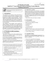
2. Locate the IFT-ECM in the control cavity of the appli-
ance and move the three-position switch to the OFF
position. See Figure 1.
3. Remove protective rubber cap from connector on the
top of the IFT-ECM. See Figure 1.
Figure 1. IFT-ECM

Hearth & Home Technologies • IFT-ACM Installation Instructions • 2326-988 • 9/16 2
6. The IFT-ACM can provide power to HHT approved kits
including fan, lights and power vent.
• To connect a fan kit to the IFT-ACM, insert the
three prong male plug from the fan into the re-
ceptacle located on the right side of the IFT-ACM.
See Figure 3.
• To connect a light kit to the IFT-ACM, remove
protective rubber cap labeled ‘LIGHTS’ and con-
nect to the female cord that was supplied in your
lights kit into the three male pins on the IFT-
ACM. DO NOT touch the three male prongs with
your bare hands as this can be a shock hazard.
See Figure 3.
• To connect a power vent kit to the IFT-ACM, re-
move protective rubber cap labeled ‘AUX’ and con-
nect to the female cord that was supplied in your
power vent kit into the three male pins on the IFT-
ACM. DO NOT touch the three male prongs with
your bare hands as this can be a shock hazard.
See Figure 3.
7. Connect the female end of the power cable that came
with the kit into the IFT-ACM. Plug the three prong
male plug into the junction box of the appliance.
9. Now you are ready to pair the IFT-ACM with the IFT-
ECM. You must perform this pairing process even if
you had previously paired the IFT-ECM with an IFT-
RC150 or IFT-RC400. See Section 2E.
10. After pairing is complete, you can verify that the IFT-
ECM recognizes the IFT-ACM with the kits that were
also installed by observing the IFT-RC400 screen. If
you installed a fan or light kit, it will show up on the
screen. The fan will only be displayed when the ame
is ON as this feature is only accessible when the ame
is ON. You can verify you have a Power Vent by turn-
ing the ame ON using the IFT-RC400 and notice if
you have a two minute countdown icon displayed on
your respective screen. Only the installed kits will be
displayed as the IFT-ACM has a smart detection fea-
ture that only activates power to the ports connected
to it and disables power to the other ports to avoid
electric hazards.
5. Connect the IFT-ACM to the IFT-ECM by aligning the
pins and tabs and pushing the IFT-ACM into the IFT-
ECM until both tabs latch in place. Ensure the IFT-
ECM and IFT-ACM are aligned with each other and
fastened securely. See Figure 2.
Figure 2. Connecting IFT-ACM and IFT-ECM
WARNING! Risk of Shock! DO NOT touch male pins.
Leave rubber cap on all ports unless port is being con-
nected to a lead.
8. Verify that the junction box is securely mounted to the
appliance chassis.
Figure 3. Fan, Lights and Power Vent Connection
POWER CORD
FAN
POWER
VENT
LIGHTS
4. Attach velcro included with the IFT-ACM to the bottom
of the ACM. See Figure 2.
ATTACH VELCRO

3 Hearth & Home Technologies • IFT-ACM Installation Instructions • 2326-988 • 9/16
E. Pairing the IFT-RC400 to the Electronic
Control Module (IFT-ECM)
CAUTION! Risk of Burns! DO NOT program the IFT
Remote Controls to the IFT-ECM when ame or cold
climate function is on or when appliance is hot.
1. On the IFT-ECM, move the ON/OFF/REMOTE switch to
the REMOTE position. The green LED will blink three
times. A few seconds later, an audible “beep” will occur
to indicate that the system is ready.
Note: If the green LED continues to blink slowly (system
is searching for a clear channel), wait until it stops before
proceeding to step 2.
2. Locate the pairing hole on the IFT-ECM. See Figure 4
Using a paper clip or similar item, press and release
the pairing button. The IFT-ECM will “beep” once and
the green LED will blink for 14 seconds. During the 14
seconds, it is normal for accessories such as lights or
fan to energize momentarily.
While the green LED on the IFT-ECM is blinking, tap anywhere
on the gray indicator bar located at the top of the IFT-RC400
screen. Tap on the pairing function as shown in Figure 5. If
the IFT-RC400 has been paired successfully to the IFT-ECM,
a double audible ‘beep” will be heard from the IFT-ECM..
3. If the pairing is unsuccessful, repeat steps 2 & 3.
Note: If additional components are added such
as blowers, lights or Power Vent after initial
pairing, the pairing process must be repeated
again to detect additional components.
NOTICE: Only one IFT-RC400 remote control and one
IFT-RC150 wireless wall switch can be programmed into
an IFT-ECM. To program both an IFT-RC400 and an IFT-
RC150 to an IFT-ECM, repeat the same steps separately
for the IFT-RC400 and the IFT-RC150.
Figure 4. Pairing IFT-ECM
REMOTE POSITION
PAIRING HOLE
GREEN LED
Figure 5. IFT-RC400 Wall Mount / Pairing Screen

Hearth & Home Technologies • IFT-ACM Installation Instructions • 2326-988 • 9/16 4
FLAME
SENSE
IGNITER
TO JUNCTION
BOX 110-120
VAC
FAN 110-120 VAC
LED
CONTROL
RF MODULE
ADAPTER
I
S
6 PIN
6V DC
BATTERY PACK
BLK
RED
BRN
ORANGE
(PILOT)
GREEN
(MAIN)
IFT-RC400
REMOTE
CONTROL
GRN/WHT/BLK
RED/BLK
RED/BLK
BLK
RED
IFT-RC150
WIRELESS
WALL SWITCH
(OPTIONAL)
(OPTIONAL)
(OPTIONAL)
APPLIANCE
ON/OFF
CONTROL
BRN
BLK
WIRE ASSEMBLY
MODULE
RESET
SWITCH
(OPTIONAL ON SOME
MODELS ONLY)
SPLITTER
BLK
RED
F. Wiring Diagram
IntelliFire™ Touch System Wiring Diagram without Power Vent
Figure 6. Wiring Diagram without Power Vent

5 Hearth & Home Technologies • IFT-ACM Installation Instructions • 2326-988 • 9/16
FLAME
SENSE
IGNITER
TO JUNCTION
BOX 110-120
VAC
FAN 110-120 VAC
LED
CONTROL
RF MODULE
ADAPTER
I
S
6 PIN
RED
BLK
ORANGE
(PILOT)
GREEN
(MAIN)
GRN/WHT/BLK
RED/
BLK
RED/
BLK
(OPTIONAL)
(OPTIONAL)
IFT-RC400
REMOTE
CONTROL
RED
BLK
BRN
BRN
JUMPER WIRE
BRN
WIRE ASSEMBLY
MODULE
RESET
SWITCH
(OPTIONAL ON SOME
MODELS ONLY)
ACCESSORY CABLE
POWER VENT
(OPTIONAL)
F. Wiring Diagram (continued)
IntelliFire™ Touch System Wiring Diagram with Power Vent
Figure 7. Wiring Diagram with Power Vent

Hearth & Home Technologies • IFT-ACM Installation Instructions • 2326-988 • 9/16 6
3. Frequently Asked Questions/Troubleshooting
Symptom Possible Cause Corrective Action
The IFT-ACM does not respond to
commands from the IFT-RC400
If IFT-ACM was newly installed
and not paired.
Refer to Section D9 and make sure that the pairing procedure
has been followed especially if the IFT-ACM was newly in-
stalled.
The power cord between
IFT-ACM and junction box is
disconnected.
Refer to Section D6 and make sure the power cable is properly
inserted into the IFT-ACM and the junction box.
IFT-ACM and IFT-ECM are not
latched.
Refer to Section D4 and check the connection between the IFT-
ACM and IFT-ECM by making sure they are latched together.
IFT-RC400 display the following
message on-screen: Call Dealer
Error: Fan
Convection blower
malfunction.
Using an RMS voltage meter, check the voltage coming out of
the fan port on the IFT-ACM when the fan is set to highest level
on the IFT-RC400. If the voltage measured is close to 120V AC
then power down the appliance and install a new fan and verify
if the issue has been resolved.
Fuse in IFT-ACM is blown.
Using an RMS voltage meter, check the voltage coming out of
the fan port on the IFT-ACM when the fan is set to highest level
on the IFT-RC400. If voltage measured is closer to zero, then
replace the IFT-ACM itself
IFT-ACM is not responding to
IFT-RC400.
Follow steps listed in the rst symptom.
Fan is not plugged into IFT-
ACM.
Check wiring and connections
Spade connectors are
miswired.
Some Fans may be connected to the IFT-ACM using spade
connectors. For safety, turn off the power to the appliance and
check to see if the wires on either end of the spade connector
do not match in color as they might be miswired.
IFT-RC400 display the following
message on-screen: Call Dealer
Error: Lights
Ember/backlighting
malfunction.
Using an RMS voltage meter, check the voltage coming out of
the lights port on the IFT-ACM when the lights are set to high-
est level on the IFT-RC400. If the voltage measured is close to
120V AC then power down the appliance and install a new light
kit and verify if the issue has been resolved.
Fuse in IFT-ACM is blown.
Using an RMS voltage meter, check the voltage coming out of
the lights port on the IFT-ACM when the lights are set to highest
level on the IFT-RC400. If voltage measured is closer to zero,
then replace the IFT-ACM itself.
IFT-ACM is not responding to
IFT-RC400.
Follow steps listed in the rst symptom.
Lights are not plugged into
IFT-ACM.
Check wiring and connections.
LED controller is not
functioning.
Some appliances come with an LED controller that plugs into
the Lights port on the IFT-ACM. Verify the wiring and check
that it is functioning. If not, replace and verify the problem is
resolved.
IFT-RC400 display the following
message on-screen: Call Dealer
Error: Power Vent
Multiple causes.
Please refer to the troubleshooting guide that came with your
Power Vent.
Lights are blinking and/or fan
and Power Vent blowers are
uctuating.
Poor quality of power from
local power station.
Check with customer if they are also noticing issues with
other unrelated appliances and if other lighting xtures are also
blinking/dimming randomly. If so, install a surge suppressor be-
tween the hearth appliance and its power source.
IFT-RC400 display the following
message on-screen: Fan will turn
on within 3 minutes
Functioning as intended.
The appliance has a three minute delay timer before the fan is
turned ON. This allows the air surrounding the appliance to be
heated before being pushed into the room.

7 Hearth & Home Technologies • IFT-ACM Installation Instructions • 2326-988 • 9/16
Please contact your Hearth & Home Technologies
dealer with any questions or concerns.
For the location of your nearest
Hearth & Home Technologies dealer,
please visit www.hearthnhome.com.
Hearth & Home Technologies
7571 215th Street West, Lakeville, MN 55044
www.hearthnhome.com
/