Page is loading ...

ON
OFF
READ AND SAVE THESE INSTRUCTIONS
This is an unvented gas-fired heater.
It uses air (oxygen) from the room
in which it is installed. Provisions for
adequate combustion and ventilation
air must be provided. Refer to page 8.
WARNINGS
If the information in this manual is not followed
exactly, a fire or explosion may result causing
property damage, personal injury or loss of life.
– Do not store or use gasoline or other flammable
vapors and liquids in the vicinity of this or any
other appliance.
– WHAT TO DO IF YOU SMELL GAS
• Do not try to light any appliance.
• Do not touch any electrical switch; do not use
any phone in your building.
• Immediately call your gas supplier from a
neighbor's phone. Follow the gas supplier's
instructions.
• If you cannot reach your gas supplier, call the
fire department.
– Installation and service must be performed by
a qualified installer, service agency or the gas
supplier.
WARNINGS
This appliance may be installed in
an aftermarket, permanently located,
manufactured (mobile) home, where
not prohibited by local codes.
This appliance is only for use
with the type of gas indicated on
the rating plate. This appliance is
not convertible for use with other
gases.
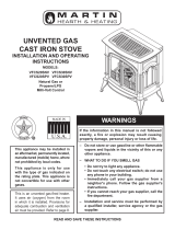
UNVENTED GAS
CAST IRON STOVE
INSTALLATION AND OPERATING
INSTRUCTIONS
SINGLE DOOR MODELS:
CSVF20SNV CSVF30SNV
CSVF20SPV CSVF30SPV
DOUBLE DOOR MODELS:
VFCS20DNV VFCS30DNV
VFCS20DPV VFCS30DPV
Natural Gas or
Propane/LPG
Milli-Volt Control

2 58D6002
CONTENTS
Important Safety Information .......................... 3
Product Features .............................................. 5
Dimensions ....................................................... 6
Getting Started ................................................. 7
Product Specifications ..................................... 8
Ignition Controls ............................................ 8
Pilot ............................................................... 8
Thermal Generator ....................................... 8
General Installation Information ..................... 9
Codes ........................................................... 9
Adequate Combustion and Ventilation Air ..... 9
Clearances / Height Requirements ............... 11
Removing Unit from Crate ............................. 13
Connecting the Gas ........................................ 14
Checking Gas Pressure ................................. 15
Connecting Remote Receiver ........................ 15
Electrical Wiring .............................................. 16
Connecting Optional Wall Switch or Checking
System Operation ....................................... 16
Log Placement ................................................ 17
Installing Logs on Grate .............................. 18
Rock Wool Installation.................................... 18
Flame Appearance .......................................... 19
Checking Pilot Flame .................................. 19
Checking the Burner Flame ........................ 20
Operating Instructions ................................... 21
For Your Safety Read Before Lighting ......... 21
Milli-Volt Control Lighting Instructions ......... 22
To Turn Off Gas to Heater ........................... 22
Match Lighting Instructions ......................... 23
Cleaning and Servicing .................................. 23
Replacement Parts List .................................. 24
VF20 Logs and Burner Assembly ............... 24
VF30 Burner Assembly ............................... 26
VFCS 30 Logs ............................................. 28
Troubleshooting .............................................. 29
Warranty .......................................... Back Cover

58D6002 3
10. This unit complies with ANSI Z21.11.2 Unvented
Heaters.
11. Do not install heater in a bathroom or bedroom unless
approved for bedroom use.
12. Correct installation of the ceramic ber logs, proper
locationoftheheater,and annualcleaning areneces-
sarytoavoidpotentialproblemswithsooting.Sooting,
resultingfromimproperinstallationor operation,can
settleonsurfacesoutsidethereplace.Seelogplacement
instructions for proper installation.
13. Avoidanydraftsthatalterburneramepatterns.Donot
allowfanstoblowdirectlyintoreplace.Donotplace
ablowerinsideburnareaofrebox.Ceilingfansmay
createdraftsthatalterburneramepatterns.Sootingand
improperburningwilloccur.
14. Caution: Candles, incense, oil lamps, etc. produce
combustionby-productsincludingsoot.Vent-freeappli-
anceswillnotlterorcleansootproducedbythesetypes
of products. In addition, the smoke and/or aromatics
(scents) may be reburnt in the vent-free appliance which
can produce odors. It is recommended to minimize the
useofcandles,incense,etc.whilethevent-freeappliance
is in operation.
15. Thisisanunventedgas-redheater.Itusesair(oxygen)
from the room in which it is installed. Provisions for
adequate combustion and ventilation air must be pro-
vided. See page 8.
IMPORTANT
Read these instructions carefully before installing or trying to operate this vent-free gas heater.
IMPORTANT SAFETY INFORMATION
8. CARBON MONOXIDE POISONING:Earlysignsof
carbonmonoxidepoisoningaresimilartotheuwith
headaches,dizzinessand/ornausea.Ifyouhavethese
signs, obtain fresh air immediately. Have the heater
servicedasitmaynotbeoperatingproperly.
9. Theinstallation mustconformwith localcodesor, in
theabsenceoflocalcodes,withtheNational Fuel Gas
Code, ANSI Z223.l/NFPA54.
Continued on page 4
WARNING
• Any change to this heater or its controls can be dangerous.
• Improper installation or use of the heater can cause serious injury or death from fire,
burns, explosion or carbon monoxide poisoning.
• Do not allow fans to blow directly into the stove. Avoid any drafts that alter burner
flame patterns.
• Do not use a blower insert, heat exchanger insert or other accessory, not approved
for use with this heater where applicable.
1.Duetohightemperatures,theapplianceshouldbelocated
outoftrafcandawayfromfurnitureanddraperies.
2. Children and adults should be alerted to the hazard of
highsurfacetemperatureandshouldstayawaytoavoid
burnsorclothingignition.
3.Youngchildrenshouldbecarefullysupervisedwhenthey
are in the same room with the appliance.
4.Donotplaceclothingorotherammablematerialonor
near the appliance.
5.Anysafetyscreenorguardremovedforservicinganappli-
ance,mustbereplacedpriortooperatingtheheater.
6.Installationandrepairshouldbedonebyaqualiedser-
vice person.
7.Topreventmalfunctionand/orsooting,anunventedgas
heater should be cleaned before use and at least annually
by a professional service person. More frequent clean-
ingmayberequiredduetoexcessivelintfromcarpet-
ing,beddingmaterial,etc.Itisimperativethatcontrol
compartments,burnersandcirculatingairpassageways
bekeptclean.
INSTALLER
Please leave these instructions with the appliance.
OWNER
Please retain these instructions for future reference.

4 58D6002
IMPORTANT SAFETY INFORMATION
Continued from page 3
16. Keep room area clear and free from combustible materi-
als,gasolineandotherammablevaporsandliquids.
17. Unventedgasheatersareasupplementalzoneheater.
They are notintendedto be a primary heating appli-
ance.
18. Unventedgasheatersemitmoistureintothelivingarea.
Inmosthomesofaverageconstruction,thisdoesnotpose
aproblem.Inhousesof extremelytight construction,
addition mechanical ventilation is recommended.
19. Duringmanufacturing,fabricatingandshipping,various
components of this appliance are treated with certain
oils,lmsorbondingagents.Thesechemicalsarenot
harmfulbutmayproduceannoyingsmokeandsmells
astheyareburnedoffduringtheinitialoperationofthe
appliance;possibly causingheadachesor eyeor lung
irritation. This is a normal and temporary occurrence.
Theinitialbreak-inoperationshouldlasttwotothree
hours with the burner at the highest setting. Provide
maximumventilationbyopeningwindowsordoorsto
allowodorstodissipate.Anyodorsremainingafterthis
initialbreak-inperiodwillbeslightandwilldisappear
with continued use.
20. Inputratings areshown inBTU perhour andare for
elevationsupto2,000feet.Forelevationsabove2,000
feet,inputratingsshouldbereduced4percentforeach
1,000feetabovesealevel.RefertotheNationalFuel
Gas Code.
21. Theapplianceanditsappliancemaingasvalvemustbe
disconnectedfromthegassupplypipingsystemduring
anypressuretestingofthatsystemattestpressuresin
excessof1/2psig(3.5kPa).
22. The appliance must be isolated from the gas supply
piping systembyclosing its equipment shutoff valve
during any pressure testing of the gas supply piping
systemattestpressuresequaltoorlessthan1/2psig
(3.5kPa).
23. Do not use this room heater if any part has been under
water.Immediately calla qualiedservice technician
to inspect the room heater and to replace any part of the
controlsystemandanygascontrolwhichhasbeenunder
water.
24. Neverburnsolidfuelsinanunventedroomheater,re-
place or stove.
25. Do not set kettles or humidifying devices on top of
stove.
26. Thestovedoor/screenmustbeclosedwhentheappli-
anceisoperating.Thescreenshallhaveopeningsfor
induction of combustion air.

58D6002 5
ON
OFF
ON
OFF
PRODUCT FEATURES
Off/Pilot/On Knob
Hi/Lo Knob
Door
Figure 1 - Cast Iron Stove
(Single Door)
Optional Remote Receiver
Fan Switch
Piezo
Handle
On/Off
Switch
Figure 2 - Cast Iron Stove
(Double Door)
Break-Away
Handle
Store Break-Away
Handle Here
Optional
Fan Switch
Off/Pilot/On Knob
Hi/Lo Knob
Piezo
Optional Remote
Receiver
On/Off
Switch

6 58D6002
A
C
B
DIMENSIONS
Figure 3 - Dimensions
CSVF20S/VFCS20D CSVF30S/VFCS30D
A
21
1
/4" 26
3
/4"
B
23" 28
1
/2"
C
16
1
/2" 19
3
/4"

58D6002 7
MAKE SURE YOU HAVE RECEIVED ALL PARTS:
Carefullyinspectthecontentsforshippingdamage.Ifanypartsaremissingordamaged,immediatelyinformthedealer
from whom you purchased the appliance. Do not attempt to install any part of the appliance unless you have all parts
in good condition.
WHAT YOU WILL NEED FOR INSTALLATION:
Youmusthavethefollowingitemsavailablebeforeproceedingwithinstallation:
Checkyourpackinglisttoverifythatalllistedpartshavebeenreceived.Youshouldhavethefollowing:
• CastIronStovewithBurnerAssembly
• Installation/OperatingInstructions
• CeramicFiberLogs
• Touch-up Paint
MillivoltcontrolledheaterdesignedtobeoperatedwithoptionaldevicesforON/OFFfunctions.
• Hand-HeldRemotewithManualReceiver
• Wall Switch with 15' Wire
• Externalregulator(forpropane/L.P.G.)
orhighpressurenaturalgas(1to2PSIsystem)
• Pipesealantapprovedforusewithpropane/L.P.G.
(Resistanttosulfurcompounds)
• Pipingwhichcomplieswithlocalcodes • Manual shutoff valve
• Sediment trap (recommended) • Tee joint
• Pipe wrench or appropriate wrench set • Screwdrivers
CAUTION
Gloves are recommended when handling ceramic fiber logs to prevent skin irritation
from loose fibers. Logs are fragile — handle with care.

8 58D6002
PRODUCT SPECIFICATIONS
NATURAL GAS
NOTE: An external regulator is required to reduce supply pressure to a maximum of 10
1
/2" w.c. on Natural Gas
systems operating at higher pressure.
MILLIVOLT PRESSURE
RegulatorPressureSetting: 3.5"w.c.
PilotRegulator: 3.5"w.c.
GasInletPressure: Max.101/2"w.c. Min.5"w.c.
IGNITION CONTROLS
Piezoignitorallowsignitionofthepilotwithouttheuseofmatches.
Milli-Volt control has four (4) positions:
OFF - Allgastotheburnerisshutoffatthevalve.
IGN - Valvepositiontolight/maintainastandingpilot.
ON - ValvepositiontoturnburnersON/OFFwithremoteswitch.
LOW/HI - Variablepositiontocontrolameheight(heatoutput).Bothfrontandrearburnersareinoperationto
providerealisticglowandyellowame.
PILOT/ODS
Thegaslogheateristtedwithaspeciallydesignedsafetypilot(ODSassembly)lightwhichsensestheamountofoxygen
availableintheroomandshutsthegaslogheateroffiftheoxygenlevelbeginstodropbelowasatisfactorylevel.Thepilot
can only be relit when adequate fresh air is available.
THERMAL GENERATOR
Themillivoltgaslogpilotisttedwithamillivoltthermopilegeneratortoprovidepowerforremoteactivation.
PROPANE / LPG
Note: An external regulator is required to reduce supply pressure to a maximum of 13" w.c.
MILLIVOLT PRESSURE
RegulatorPressureSetting: 10"w.c.
GasInletPressure: Maximum13"w.c.
Minimum11"w.c.
Model Number Type
Gas Rate
Max. BTU/Hr Min. BTU/Hr
CSVF20SNV/VFCS20DNV (G-EBL-ES-EMB)
CSVF30SNV/VFCS30DNV (G-EBL-ES-EMB)
Milli-Volt
Milli-Volt
10,000
32,000
6,000
20,000
Model Number Type
Gas Rate
Max. BTU/Hr Min. BTU/Hr
CSVF20SPV/VFCS20DPV (G-EBL-ES-EMB)
CSVF30SPV/VFCS30DPV (G-EBL-ES-EMB)
Milli-Volt
Milli-Volt
10,000
32,000
6,000
20,000

58D6002 9
CODES
Adheretoalllocalcodesor,intheirabsence,thelatesteditionofTHENATIONALFUELGASCODEANSIZ223.1or
NFPA54whichcanbeobtainedfrom…
American National Standards Institute, Inc.
1430Broadway
NewYork,NY10018
or
National Fire Protection Association, Inc.
BatterymarchPark
Quincy,MA02269
GENERAL INSTALLATION INFORMATION
ADEQUATE COMBUSTION AND VENTILATION AIR
Thisheatershall notbeinstalledina connedspaceorunusuallytight constructionunlessprovisionsareprovidedfor
adequate combustion and ventilation air.
The National Fuel Gas Code, (ANSI Z223.1/NFPA54),denesaconnedspaceasaspacewhosevolumeislessthan50
cubicfeetper1,000BTUperhour(4.8m
3
perkw)oftheaggregateinputratingofallappliancesinstalledinthatspaceand
anunconnedspaceasaspacewhosevolumeisnotlessthan50cubicfeetper1,000BTUperhour(4.8m
3
perkw)ofthe
aggregateinputratingofallappliancesinstalledinthatspace.Roomscommunicatingdirectlywiththespaceinwhichthe
appliancesareinstalled,throughopeningsnotfurnishedwithdoors,areconsideredapartoftheunconnedspace.
UNUSUALLY TIGHT CONSTRUCTION IS DEFINED AS CONSTRUCTION WHERE…
a) wallsandceilingsexposedtotheoutsideatmospherehaveacontinuouswatervaporretarderwitharatingof1perm
(6x10
11
kgperpa-sec-m
2
)orlesswithopeningsgasketedorsealed;
b) weatherstrippinghasbeenaddedonopenablewindowsanddoors,and
c) caulkingorsealantsareappliedtoareassuchasjointsaroundwindowanddoorframes,betweensoleplatesandoors,
betweenwall-ceilingjoints,betweenwallpanels,atpenetrationsforplumbing,electrical,andgaslines,andatother
openings.
WARNING
Do not install the heater …
• Where curtains, furniture, clothing, or other flammable objects are less than 42" from
the front of the heater.
• In high traffic areas.
• In windy or drafty areas.

10 58D6002
ON
OFF
L
2
L
1
W
H
GENERAL INSTALLATION INFORMATION
Thefollowingformulacanbeusedtodeterminethemaximumheaterratingperthedenitionofunconnedspace:
BTU/Hr = (L1 + L2) Ft x (W) Ft x (H) Ft
50
Considertwoconnectingroomswithanopenareabetween,withthefollowingdimensions:
L1 = 15
1
/2 Ft., L2 = 12 Ft., W = 12 Ft., H = 8 Ft.
BTU/Hr = (15
1
/2 + 12) x (12) x (8)
50
If there were a door between the two rooms the calculation would be based only on the room with the heater.
BTU/Hr = (15
1
/2) x (12) x (8)
50
Figure 4 - Example of a Large Room with 1/2 Wall Divider
Counter
Cast Iron Stove
x 1000
x 1000 = 52800 BTU/Hr
x 1000 = 29760 BTU/Hr
WARNING
If the area in which the heater may be operated is smaller than that defined as an
unconfined space or if the building is of unusually tight construction, provide adequate
combustion and ventilation air by one of the methods described in the National Fuel
Gas Code, ANSI Z223.1, NFPA54, Section 5.3 or applicable local codes.

58D6002 11
D
Minimum
to Either
Side Wall
E
Minimum
A
G
G
D
Minimum
to Either
Side Wall
F Minimum
F
Minimum
36"
in Front
C
B
Mantel Clearance from
Top of Unit
Side, Measured from Top
Rear
Measured
from Back
Corner
Measured
From Top
Corners
Product
Min. Ceiling
from Floor
Max.
Protrusion Min. Height Right Left
A B C D E F G
VF20
72" 12" 16" 1" 1" ½" 1½"
VF30
72" 12" 18" 2" 2" 1" ½"
CLEARANCES / HEIGHT REQUIREMENTS
Side
Wall
Mantel
Figure 5 - Minimum Clearance to Walls and Ceiling
Front View
Corner Installation
Wall Installation
Side View
Ceiling
Ceiling
Floor
Side
Wall
Floor
WARNING
The dimensions shown in Figure 5 are minimum clearances to maintain in installing this
heater. Left and right clearances are determined when facing the front of the heater.
Follow these instructions carefully to ensure safe installation. Failure to follow
instructions exactly can create a fire hazard.
The appliance cannot be installed on a carpet, tile or other combustible material other
than wood flooring, the appliance shall be installed on a metal, wood or noncombustible
material panel extending full width and depth of the appliance.

12 58D6002
ON
OFF
A
C
B
CLEARANCES / HEIGHT REQUIRMENTS
Figure 6 - Placing Stove in Alcove
Note: Maintain minimum side and back clearances when placing stove in alcove.
Height From
Hearth
A
Width
B
Depth
C
VF20
38½" 23" 36"
VF30
52" 34" 36"
Tested Minimum Alcove Dimensions

58D6002 13
PILOT
OFF
REMOTE CONTROL
LOGS
ON
OFF
LOGS
PILOT
OFF
REMOTE CONTROL
LOGS
REMOVING UNIT FROM CRATE
1. Removetwo(2)straps. See Figure 7.
2. Openplasticbagandslidetobottomofunit. See
Figure 8.
3. Liftuponashlipandpivotdowntoopencontrol
door. See Figure 9.
4. Liftuponfront.Pivotbottomoffrontout.Remove
front. See Figure 9.
5. Liftscreentoremove.
6. Removelogboxfrominsideofunit.
7. Liftunitoffpallet.Liftunituphighenoughtoclear
uprightsupportsunitissittingon.
Note: You will need at least two (2) strong
people to lift unit off of pallet.
Figure 7 - Removing Straps and Plastic from Unit
Figure 8 - Opening Control Door and Removing
Hearth Door
Figure 9 - Removing Log Box
Straps
Plastic
Bag
Control
Door
Ash Lip
Hearth
Door
Log
Box
Pallet

14 58D6002
Pipe Coupling
To Heater
Valve
Gas Supply
Inlet
CONNECTING THE GAS
NOTICE: A qualified gas appliance installer must connect the heater to the gas supply. Consult all
local codes.
IMPORTANT: Holdheatervalvermlywithawrenchtopreventmovementwhenconnectingtoinletpipe.
Manual Shutoff
Valve
Pipe
Stainless
Flexible Tube
Figure 10 - Gas Connection
Always use an external regulator for all propane/LPG heaters and high pressure one to two-pound systems only, to
reducethesupplytankpressuretoamaximumof13"w.c.Thisisinadditiontotheinternalregulatorintheheatervalve.
Locations that the Pressure
Tapping Point May Be Installed
CAUTION
Use new black iron or steel pipe. Internally tinned copper or copper tubing can be used
per National Fuel Code, section 2.6.3, providing gas meets hydrogen sulfide limits, and
where permitted by local codes. Gas piping system must be sized to provide minimum
inlet pressure (Listed on Data Plate) at the maximum flow rate (BTU/Hr). Undue pressure
loss will occur if the pipe is too small.
A manual shutoff valve must be installed upstream of the appliance. Union tee and
plugged 1/8" NPT pressure tapping point should be installed upstream of the appliance.
See Figure 10.
CAUTION
CHECK GAS TYPE: The gas supply must be the same as stated on the heater’s rating
plate. If the gas supply is different, DO NOT INSTALL THE HEATER. Contact your dealer
for the correct model.

58D6002 15
ON
OFF
CHECKING GAS PRESSURE and CONNECTING REMOTE RECEIVER
MILLIVOLT CONTROL (FIGURE 11)
Thevalveregulatorcontrolstheburnerpressurewhichshould
becheckedatthepressuretestpoint.
Ifoutletpressureislow,checkinletpressureagainstdataplates
or manual.
Turncapturedslottedscrewcounterclockwise2or3turnsand
thenplacetubingtopressuregaugeovertestpoint(Usetest
point“OUT”closestto controlknob).Aftertakingpressure
reading,besureandturncapturedscrewclockwisermlyto
re-seal.Donotovertorque.Checkforgasleaks.
NOTE: Remove control panel to access gas valve.
Figure 11 - Pressure Test Point Location
Milli-Volt Control
Test Port “OUT”
CONNECTING REMOTE RECEIVER
1. Removecoveroncontrolpaneltoshowopeningfor
remote receiver. See Figure 12.
2. FollowremotereceiverInstructionstomakeallneces-
sarywiringconnections.
3. Placeremotereceiverintheopeningofcontrolpanel.
Use two screws provided to attach remote receiver to
the control panel. See Figure 12.
Figure 12 - Installing Remote Receiver
Remote Receiver
Cover
NOTE: Do not place remote in combustion chamber.
Theheatergasinletconnectionis3/8"NPTatthevalve.The
inletislocatedonleftsideofstove.Removefrontcontrol
plate to better access the inlet.
Whentighteningupthejointtothevalve,holdthevalvesecurely
with a wrench to prevent movement.
Testallgasjointsfromthegasmetertotheheatervalvefor
leaksusingagasanalyzerorsoapandwatersolutionaftercompletingconnection. DO NOT USE AN OPEN FLAME.
CheckthegaspressurewiththeapplianceburningandthecontrolsettoHIGH.
WARNING
Connecting directly to an unregulated
propane/L.P.G. tank can cause an
explosion.

16 58D6002
Label all wires prior to
disconnection when
servicing controls.
Wiring errors can cause
improper and dangerous
operation. Verify proper
operation after servicing.
ELECTRICAL WIRING (MILLI-VOLT)
Themilli-voltvalveisaself-poweredcombinationgascontrolTHAT DOES NOT REQUIRE 110 VAC TO OPERATE.
On/Off
Switch
On/Off
Switch
ODS
Pilot
Wall
Switch
Optional Wall
Switch or
Remote
ODS Pilot
Millivolt
Valve
Spade Terminal
3
1
2
CONNECTION
1 = TP
2 = TP, TH
3 = TH
Figure 13 - Wiring Diagram
CONNECTING OPTIONAL WALL SWITCH
1. Use18awg,two-wirecable,15feetmaximumlength.
2. Atoneendofthecable,connectbothwirestothewallswitch.Attheotherend,connectonewiretoTP/THandone
wiretoTH,orconnectthewallswitchtothetwomale(0.25")terminalsontheleftsideoftheunit.Thecolorofthe
wires does not matter.
A. COMPLETE MILLIVOLT SYSTEM CHECK
("A" Reading - On/Off switch contacts CLOSED - Control Knob “ON” - Main Burners should turn ON)
a. Ifthereadingismorethan175millivoltsandtheautomaticvalvestilldoesnotcomeon-replacethevalve.
b. Iftheclosedcircuitreading("A"reading)islessthan175millivolts,determinecauseforlowreading-proceedas
follows:
B. THERMOPILE OUTPUT READING CHECK
(“B” Reading - On/Off switch contacts OPEN - Main burner OFF)
Checkgaspressuretotheunit.Ifgaspressureiswithinminimumandmaximumondataplate,thenreplacepilot.Ifthe
minimummillivoltreadingisnotobtainable,replacepilot.
CHECKING SYSTEM OPERATION
The millivolt system and individual compo-
nentsmaybecheckedwithamillivoltmeter
having a 0-1000mv range. Conduct each
checkshowninchartbyconnectingmeter
test leads to terminals as indicated.
Switch
CHECK
TEST
TO TEST CONNECT METER
LEADS TO TERMINALS
METER READING
SHOULD BE
A COMPLETE 2 & 3 SYSTEM MINIMUM 175mv
B THERMOPILE
OUTPUT
1 & 2 SYSTEM 500mv OR MORE

58D6002 17
PILOT
OFF
REMOTE CONTROL
Left
Bottom
Log #2
Back Log
#1
Top Left
Log #4
LOG PLACEMENT
VF30 INSTALLING LOGS ON GRATE
(See Figure 14)
1. Installbacklog(#1)onrearlogsupportbracket.
2. Installleftbottomlog(#2)onleftlogsupportbracketinfront
ofbacklog.
3.Installrightbottomlog(#3)onrightlogsupportbracketin
frontofbacklog.
4. Installtopleftlog(#4)ontopofleftbottomlog.
5. Installtoprightlog(#5)ontopofrightbottomlog.
Figure 14 - Installing Logs to Grate (VF30)
Before you begin —Thisunitissuppliedwithfourceramicberlogs.Donothandletheselogswithyourbarehands.
Always wear gloves to prevent skin irritation from ceramic bers.Afterhandlingthelogs,washyourhandsgentlywith
soapandwatertoremoveanytracesofbers.
Right
Bottom
Log #3
Right
Top Log
#5
Rear Log
Support
Bracket
Left Log
Support
Bracket
Right Log
Support
Bracket
WARNING
The positioning of the logs are critical to the safe and clean operation of this heater.
Sooting and other problems may result if the logs are not properly and firmly positioned
in the appliance. Never add additional logs or embellishments such as pine cones,
vermiculite or rock wool to the heater. Only use the logs supplied with the unit.
Failure to position the parts in accordance with diagrams below or to use only
parts specifically approved for this heater may result in property damage or
personal injury.
CAUTION
During initial operation of the new
heater, burning logs will give off
a paper burning smell and orange
flames will be present. Simply open
the windows for a few hours to vent
the odor.

18 58D6002
PILOT
OFF
REMOTE CONTROL
VF20 INSTALLING LOGS ON GRATE
(See Figure 15)
1. Installbacklog(#1)onbackofburnerassembly.
2. Installfrontlog(#2)on2pegsonburnerassembly.
ROCK WOOL INSTALLATION (VF30 UNITS ONLY)
Figure 16 - Rock Wool Installation
1. Breakrockwoolintodime-sizedpieces.
➞
2. Placerockevenlyacrossrockwooltrayandfrontburnerasshownin
Figure 16.
• Rock wool depth must not be more than 1".
• Do not place rock wool past the bend in rock wool tray.
• Do not place rock wool on rear burner.
Rock Wood
Tray
Rock Wool
Bend in Rock
Wool Tray
LOG PLACEMENT
Figure 15 - Installing Logs to Grate (VF20)
WARNING
Rock wool must be placed
correctly. Placing rock wool
in wrong area will create high
carbon monoxide.

58D6002 19
Flames from the pilot, front and rear burner should be visually checked as soon as the heater is installed.
Inaddition,periodicallychecktheamesvisuallyduringoperation.
CHECKING PILOT FLAME
The pilot flame must always be present when the heater is in operation. It should just touch the top of the ther-
mocouple tip for natural. See Figure 17 forcorrectpilotame.
Ifthepilotamedoesnottouchthethermocouple,thentheburnerscannotfunctionreliably.See Figure 18 for incorrect
shapeofpilotame.
MILLI-VOLT CONTROL
Figure 17 - Correct Appearance of Pilot Flame
Figure 18 - Incorrect Appearance of Pilot Flame
Thermocouple
for Natural
Thermocouple
for LP
Thermocouple
for LP
Thermocouple
for Natural
FLAME APPEARANCE

20 58D6002
PILOT
OFF
REMOTE CONTROL
FLAME APPEARANCE
CHECKING BURNER FLAME
In normal operation at full rate after 15 minutes, the following flame appearances should be observed:
Theleftandrightrearamesshouldbeyellowandextend1"-2"abovemiddlelogs.Theyellowamesshouldnot contact
thelogs.Thereshouldbeglowingembersonthefrontsurfaceofthemiddlelog.Note: The flames and embers will be
an opaque orange color during the burn off time.
Figure 19 - Correct Flame Appearance
OPERATING INSTRUCTIONS
Avoid any drafts that alter burner flame patterns. Do not allow fans to blow directly into the stove. Do not place
ablowerinsidetheburnareaofthestove.Ceilingfansmaycreatedraftsthatalteramepatterns.Sootingandimproper
burningwillresult.
Duringmanufacturing,fabricatingandshipping,variouscomponentsofthisappliancearetreatedwithcertainoils,lmsor
bondingagents.Thesechemicalsarenotharmful,butmayproduceannoyingsmokeandsmellsastheyareburnedoffduring
theinitialoperationoftheappliance,possiblycausingheadachesoreyeorlungirritation.This is a normal and temporary
occurrence.
Theinitialbreak-inoperationshouldlasttwotothreehourswiththeburneratthehighestsetting.Providemaximumventila-
tionbyopeningwindowsordoorstoallowodorstodissipate.Anyodorsremainingafterthisinitialbreak-inwillbeslight
and will disappear with continued use.
Middle Log
Middle Log
/