Vega VEGASWING 61 Product information

Type
Product information

This manual is also suitable for

Product information
Vibrating
Level detection in liquids
VEGASWING 51
VEGASWING 53
VEGASWING 61
VEGASWING 63
VEGASWING 66
Document ID: 30115
2
Contents
Vibrating
30115-US-191111
Contents
1 Measuring principle ............................................................................................................................................................................................... 3
2 Type overview ......................................................................................................................................................................................................... 7
3 Instrument selection .............................................................................................................................................................................................. 8
4 Instrument features ............................................................................................................................................................................................... 9
5 Accessories .......................................................................................................................................................................................................... 10
6 Selection criteria .................................................................................................................................................................................................. 11
7 Housing overview - VEGASWING 61, 63, 66 ...................................................................................................................................................... 12
8 Mounting ............................................................................................................................................................................................................... 13
9 Relay output .........................................................................................................................................................................................................14
10 Transistor output ..................................................................................................................................................................................................15
11 Contactless electronic switch ............................................................................................................................................................................17
12 Two-wire output ....................................................................................................................................................................................................18
13 NAMUR output ......................................................................................................................................................................................................19
14 IO-Link output.......................................................................................................................................................................................................20
15 Adjustment ........................................................................................................................................................................................................... 21
16 Dimensions ...........................................................................................................................................................................................................23
Take note of safety instructions for Ex applications
Please note the Ex specic safety information that you can nd at www.vega.com and that comes with each instrument. In hazardous areas you
should take note of the appropriate regulations, conformity and type approval certicates of the sensors and power supply units. The sensors must
only be operated on intrinsically safe circuits. The permissible electrical values are stated in the certicate.
3
Measuring principle
Vibrating
30115-US-191111
1 Measuring principle
Measuring principle
VEGASWING is a point level sensor with tuning fork for point level detec-
tion.
It is designed for industrial use in all areas of process technology, but pref-
erably in liquids.
The vibrating element (tuning fork) is piezoelectrically energized and vi-
brates at its mechanical resonance frequency. The piezo elements are me-
chanically xed and are hence not subject to temperature shock limitations.
If the vibrating element is submerged in the product, the vibrating frequency
changes. This change is detected by the integrated electronics module and
converted into a switching command.
Conguration
1
2
3
Fig. 1: Vibrating level switch VEGASWING, for example VEGASWING 61 with plastic
housing
1 Housing lid
2 Housing with electronics
3 Processtting
Typical applications are overll and dry run protection. Thanks to its simple
and robust measuring system, VEGASWING is virtually unaected by the
chemical and physical properties of the liquid.
It also works when subjected to strong external vibrations or changing
products.
Function monitoring
The electronics module of VEGASWING continuously monitors the follow-
ing criteria:
Strong corrosion or damage on the tuning fork
Loss of vibration
Line break to the piezo drive
If one of the stated malfunctions is detected or in case of voltage supply, the
electronics takes on a dened switching status, for example the switching
output is open (safe state).
Function test
The recurring function test is used to check the safety function, in order to
reveal possible dangerous unrecognized faults. The function of the measur-
ing system must be checked in regular, adequate intervals.
There are two dierent ways to carry out a function test:
VEGASWING 61, 63, 66 with two-wire electronics in conjunction with a
VEGATOR controller.
Test key on the VEGATOR controller
VEGASWING 61, 63, 66 with two-wire electronics in conjunction with a
VEGALOG processing system or a PLC.
Brief interruption of the connection cable to the PLC
1.2 Application examples
Chemical industry - Solvents
Fig. 2: Level detection in vessels with solvents
Apart from the continuous level measurement, level detection is an essen-
tial safety feature for storage tanks. Many modern sensors for continuous
level measurement are actually approved as overll protection system,
however, a second, physically dierent measuring system provides the best
safety and redundance.
Thanks to their manifold application possibilities, VEGASWING vibrating
level switches are ideal for all applications in the area of liquids warehous-
ing. A large number of electrical and mechanical versions ensures simple
integration into existing control systems.
Advantages:
Various electrical versions
Product-independent
Universal level detection for all liquids
4
Measuring principle
Vibrating
30115-US-191111
Chemical industry - reactors
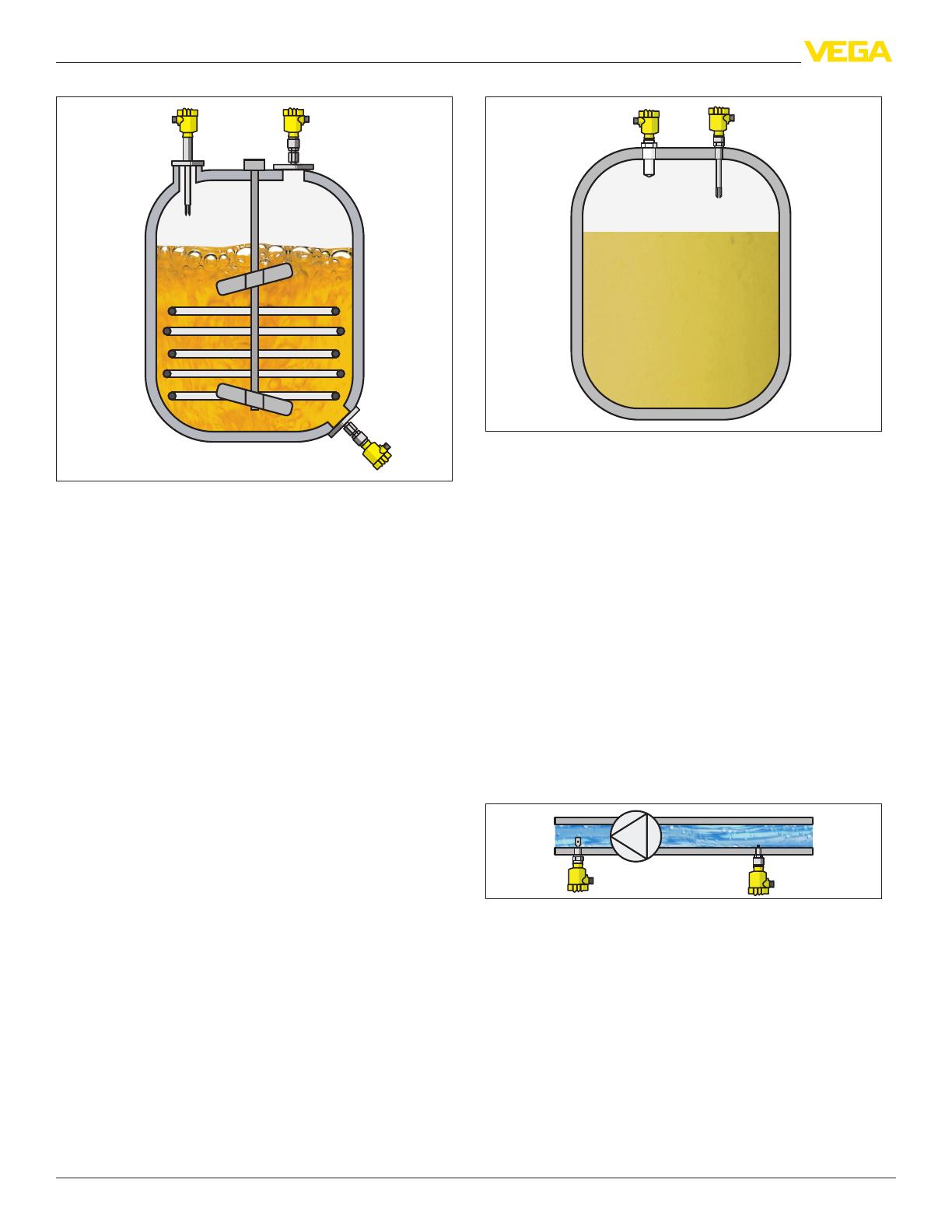
Fig. 3: Level detection in chemical reactors
Because they prevent overlling or dry running of pumps, sensors for level
detection are an important safety element in reactors. Due to their universal
applicability, VEGASWING level switches are well suited for use in reaction
vessels. Even high viscosities, temperatures up to 250 °C and pressure up
to 64 bar do not impair their function.
To provide the required chemical resistance, high resistance materials and
enamelled versions are available.
In toxic products, the VEGASWING version with metallic process separa-
tion ensures a high level of safety. To prevent product leakage even in case
of corrosion on the tuning fork, a glass seal is also welded in. This ensures
optimum protection.
To provide optimal resistance to the measured medium, whatever its com-
position and corrosive properties may be, sensors made of 316L or Alloy, or
sensors in plastic-coated and enamelled versions, are available.
Thanks to their manifold application possibilities, VEGASWING vibrating
level switches are ideal for all applications in the area of liquids storage. A
large number of electrical and mechanical versions enables simple integra-
tion into existing control systems.
Advantages:
Various electrical versions
Product-independent
Completely gas-tight
High reliability
Universal level detection for all liquids
Water/Sewage water plants
Fig. 4: Precipitants in sewage water processing
Chemicals are required for sewage water treatment. They are applied to
promote chemical precipitation. Phosphates and nitrates are thus sedi-
mented and separated. In addition to lime water and ferric chloride, various
acids and alkalis are stored for use in digested sludge treatment and
neutralisation.
These substances are subject to the regulations covering water-endanger-
ing substances. Overll protection systems thus have to be installed on the
storage tanks.
Since they prevent the overlling of vessels containing toxic products, sen-
sors for level detection are an important safety element.
Due to their versatile nature, VEGASWING vibrating level switches are
also well qualied for use with water-endangering substances. To provide
optimal resistance to the measured medium, whatever its composition and
corrosive properties may be, sensors made of 316L or Alloy, as well as
sensors in plastic-coated or enamelled versions, are available.
Advantages:
Small non-repeatability
High-resistance sensor materials such as PFA, ECTFE, Alloy C22
(2.4602), enamel
Pipelines
Fig. 5: Dry run protection in pipelines
Monitoring of levels is also important in pipelines, as dry running often
causes damage or complete breakdown of the pumps.
The VEGASWING level switch is recommended as dry run protection sys-
tem, e.g. for drinking water pumps. With a fork only 40 mm (1.575 in) long
(VEGASWING series 60), this level switch functions quite reliably, even in
pipes with small diameters from DN 32.
Advantages:
Universal level detection for all liquids
Adjustment and maintenance-free
5
Measuring principle
Vibrating
30115-US-191111
Food processing industry
Fig. 6: Level detection and dry run protection in a tank storing milk
The processes in food processing tanks, e.g. for milk, place heavy
demands on the installed measurement technology. High pressures and
temperatures are generated during sterilization and cleaning of the tanks.
That means that the implemented level measuring instruments and level
detectors must meet the requirements of hygienic design. The innocuous-
ness of all wetted materials must be proven and optimum cleanability must
be ensured through hygienic technical design.
VEGASWING is installed for level detection and as dry run protection sys-
tem. The tuning fork is highly polished for use in sensitive foodstus such
as milk.
Advantages:
Universal level detection for all liquids
High-resistance sensor materials such as PFA, ECTFE, Alloy C22
(2.4602), enamel
Adjustment and maintenance-free
Cryogenic processes
Fig. 7: Level detection in a liquid gas vessel
The extremely low temperatures in liquid tanks are a challenge fo the
installed measurement instrumentation. Petroleum gas is stored for
example at -162 °C (-260 °F) and nitrogen even at -196 °C (-321 °F). The
VEGASWING 66 with -196 … +450 °C (-321 … +482 °F) can cover a large
temperature range.
Advantages:
Universal use, because only low min. density of the medium required.
Double safety through Second Line of Defense
Cost-optimized setup without medium
Steam vessel
Fig. 8: Level detection in a steam boiler
Point level measurement in steam boilers monitors the high and low
water level of the vessel. The point level measurement is independent of
vessel pressure and temperature as well as the density of the water or the
saturated steam. With its pressure range up to 160 bar (2320 psig) and a
max. temperature up to +450 °C (+482 °F), the VEGASWING 66 covers the
6
Measuring principle
Vibrating
30115-US-191111
majority of saturated steam applications.
Advantages:
Reliable and quick function test
Double safety through Second Line of Defense
Flexible and high availability in applications up to SIL3
7
Type overview
Vibrating
30115-US-191111
2 Type overview
VEGASWING 51 VEGASWING 53 VEGASWING 61 VEGASWING 63 VEGASWING 66
Applications Point level measurement
in liquids
Point level measurement
in liquids
Point level measurement
in liquids
Point level measurement
in liquids
Point level measurement
in liquids
High and low process
temperatures
High process pressures
Length - 80 … 6000 mm
(3.15 … 236.22 in)
- 80 … 6000 mm
(3.15 … 236.22 in)
260 … 3000 mm
(10.24 … 118.11 in)
Process tting Thread G½, G¾, G1
Hygienic ttings
Thread G½, G¾, G1
Hygienic ttings
Thread G¾, G1
Flanges
Hygienic ttings
Thread G¾, G1
Flanges
Hygienic ttings
Thread G1
Flanges
Process temperature -40 … +100 °C (-
40 … +212 °F)
-40 … +150 °C (-
40 … +302 °F) with
temperature adapter
-40 … +100 °C (-
40 … +212 °F)
-40 … +150 °C (-
40 … +302 °F) with
temperature adapter
-50 … +150 °C (-
58 … +302 °F)
-50 … +250 °C (-
58 … +482 °F) with
temperature adapter
-50 … +150 °C (-
58 … +302 °F)
-50 … +250 °C (-
58 … +482 °F) with
temperature adapter
-196 … +450 °C (-
321 … +482 °F)
Process pressure -1 … 64 bar (-
14.5 … 928 psig)
-1 … 64 bar (-
14.5 … 928 psig)
-1 … 64 bar (-
14.5 … 928 psig)
-1 … 64 bar (-
14.5 … 928 psig)
-1 … 160 bar (-
14.5 … 2321 psig)
Signal output Transistor
Contactless electron-
ic switch
IO-Link
Transistor
Contactless electron-
ic switch
IO-Link
Relay
Transistor
Two-wire
NAMUR
Contactless electron-
ic switch
Relay
Transistor
Two-wire
NAMUR
Contactless electron-
ic switch
Relay
Transistor
Two-wire
Ruggedness + + + + +
Sensitivity + + ++ ++ ++
Buildup ++ ++ + + +
Cleanability ++ ++ ++ ++ ++
Installation length ++ ++ ++ ++ ++
8
Instrument selection
Vibrating
30115-US-191111
3 Instrument selection
VEGASWING 51, 53
VEGASWING 51 is a universal level switch with small dimensions. Indepen-
dent of the mounting position, it detects the level reliably and with millimetre
accuracy. The instrument can be used for full or empty alarm, as approved
overll protection or dry run or pump protection in vessels and pipelines.
VEGASWING 51 is an economical solution with a small, compact stain-
less steel housing and is available with the electronics versions transistor
output, contactless electronic switch and IO-Link.
On VEGASWING 53, the switching point can be adapted to the process
with a freely selectable extension tube.
VEGASWING 61, 63
VEGASWING series 60 level switches are instruments from the VEGA
plics
®
series, which are available in standard and tube version. Thanks
to the many dierent process ttings, housings and electronics versions,
plics
®
instruments can be congured in versions suitable for any appli-
cation. They have all standard approvals and the tuning fork can also be
polished, e.g. for applications in the food processing industry.
On VEGASWING 63, the switching point can be adapted to the process
with a freely selectable extension tube.
VEGASWING are virtually unaected by product properties and thus do not
have to be adjusted.
The level switches are used in applications with process temperatures up to
+250 °C (+482 °F) and pressures of up to 64 bar (928 psig).
They detect liquids from 0.5 … 2.5 g/cm³ (0.018 … 0.09 lbs/in³).
All electronics are qualied for the function "overll and dry run protection"
according to IEC 61508 and 61511 for SIL2, in redundant version also up
to SIL3.
VEGASWING 66
The point level sensors VEGASWING 66 are instruments from the VEGA
plics
®
series and available in standard and tube version. The instruments
are suitable for liquids with extremely low and high process temperatures.
With their many dierent process ttings, housings and electronics ver-
sions, plics
®
instruments can be ideally congured for any application. They
have all standard approvals.
VEGASWING are virtually unaected by product properties and thus do not
have to be adjusted.
The level switches are used in applications with process temperatures
up to -196 … +450 °C (-321 … +482 °F) and pressures of up to 160 bar
(2321 psig).
They detect liquids from 0.42 to 2.5 g/cm³ (0.015 to 0.09 lbs/in³).
All electronics are qualied for the function "overll and dry run protection"
according to IEC 61508 and 61511 for SIL2, in homogeneous redundant
version also up to SIL3.
9
Instrument features
Vibrating
30115-US-191111
4 Instrument features
Second Line of Defense
To increase safety in applications with dangerous or toxic products, the
series 60 sensors can be ordered with a welded, gas-tight feedthrough
(Second Line of Defense).
Temperature adapter
For VEGASWING 61 and 63, a temperature adapter is optionally available.
With it you can increase the max. permissible process temperature from
+150 °C (+302 °F) to +250 °C (+482 °F).
SIL qualication
As an option, the sensors of VEGASWING series 60 can be ordered with
SIL qualication. The sensors can thus be used in applications according to
SIL2. In a homogeneously redundant conguration, they can also be used
up to SIL3.
Coating
To make the use of VEGASWING series 60 sensors possible in aggressive
or corrosive products, dierent coatings are optionally available. The follow-
ing coating materials can be used depending on the required resistance.
Our application engineers will be pleased to give you advice on resistances
and the possibilities the sensors oer.
ECTFE
PFA
Enamel
10
Accessories
Vibrating
30115-US-191111
5 Accessories
Protective cover
To protect the sensor against pollution and strong heat due to the sun, you
can snap a weather protective cover onto the sensor housing.
Fig.9:Weatherprotectioncoverindierentversions
Display module PLICSLED
The display module allows you to clearly display the switching status of the
sensor. For this purpose, housing lids with inspection windows in dierent
materials are available. The plastic housing is optionally available with a
transparent lid through which you can see the indicator lamp from the side.
Fig. 10: Display module PLICSLED
Lock tting
VEGASWING in tube version can be mounted with a lock tting for innitely
variable height adjustment. Take note of the pressure specications of the
lock tting.
Keep in mind that the lock tting must not be used with coated instrument
versions.
Fig.11:Locktting-e.g.ARV-SG63.3forVEGASWING63upto64bar
Plug connector
Instead of a cable gland, you can also use various plug connectors for mak-
ing connections. The following plug connectors are available for VEGAS-
WING series 60:
ISO 4400
ISO 4400 with Quick-On tting
Amphenol-Tuchel
Harting HAN 7D
Harting HAN 8D
M12 x 1
Fig.12:Plugconnector-e.g.VEGASWINGseries60withISO4400plug
There are no cable glands possible for the VEGASWING of series 50. The
instruments are available with the following plug connectors:
ISO 4400
ISO 4400 with Quick-On tting
M12 x 1
11
Selection criteria
Vibrating
30115-US-191111
6 Selection criteria
VEGASWING VEGASWING VEGASWING 66
Version 51
Compact
53
Tube
61
Compact
63
Tube
66
Compact
66
Tube
Vessel Probe length max. 3 m
Probe length max. 6 m
Cryogenic applications
Pipelines
Process Aggressive liquids
Bubble or foam generation
Wave movements at the surface
Steam or condensation
Buildup
Changing density
Temperatures up to +150 °C
Temperatures up to +250 °C
Temperatures > +250 °C
Pressures up to 64 bar
Pressures up to 160 bar
Hygienic applications
Narrow space above the vessel
Steam boiler application
Process tting Threaded ttings
Flange connections
Hygienic ttings
Sensor Stainless steel
Coating
Polished version
SIL qualication
Industry
Chemical
Power generation
Foodstus
Oshore
Petrochemical
Pharmaceutical
Shipbuilding
Environment and recycling industry
Water
Waste water
● = optimum suitability
○ = possible with limitations
– = not recommended
12
Housing overview - VEGASWING 61, 63, 66
Vibrating
30115-US-191111
7 Housing overview - VEGASWING 61, 63, 66
Plastic PBT
Protection rating IP66/IP67 IP66/IP67
Version Single chamber Double chamber
Application area Industrial environment Industrial environment
Aluminium
Protection rating IP66/IP67, IP66/IP68 (1 bar) IP66/IP67, IP66/IP68 (1 bar)
Version Single chamber Double chamber
Application area Industrial environment with increased me-
chanical stress
Industrial environment with increased me-
chanical stress
Stainless steel 316L
Protection rating IP66/IP67 IP66/IP67, IP66/IP68 (1 bar) IP66/IP67, IP66/IP68 (1 bar)
Version Single chamber, electropolished Single chamber, precision casting Double chamber, precision casting
Application area Aggressive environment, food processing,
pharmaceutical
Aggressive environment, extreme mechan-
ical stress
Aggressive environment, extreme mechan-
ical stress
13
Mounting
Vibrating
30115-US-191111
8 Mounting
Switching point
In general, VEGASWING can be installed in any position. The instrument
only has to be mounted in such a way that the vibrating element is at the
height of the desired switching point.
The tuning fork has lateral markings (notches) marking the switching point
with vertical installation. The switching point refers to the medium water with
basic setting of the density switch ≥ 0.7 g/cm³ (0.025 lbs/in³).
Keep in mind that foams with a density > 0.45 g/cm³ (0.016 lbs/in³) are
detected by the sensor.
Mounting socket
The vibrating element should protrude into the vessel to avoid buildup. For
that reason, avoid using mounting bosses for anges and screwed ttings.
This applies particularly to horizontal installation and use with adhesive
products.
Agitators
Due to agitators, vibration or similar, the level switch can be subjected to
strong lateral forces. For this reason, do not use an overly long extension
tube for VEGASWING 63 or 66, but check if a VEGASWING 51 or 61 level
switch without tube extension couldn't be used instead, mounted on the
side of the vessel in horizontal position.
Extreme vibration caused by the process or the equipment, e.g. agitators
or turbulence in the vessel, can cause the extension tube of VEGASWING
to vibrate in resonance. This leads to increased stress on the upper weld
joint. Should a longer tube version be required, you can provide a suitable
support or guy directly above the vibrating element to secure the extension
tube.
This measure applies mainly to applications in Ex areas. Make sure
that the tube is not subject to bending stress due to this measure.
Inowing medium
If VEGASWING is mounted in the lling stream, unwanted false measure-
ment signals can be generated. For this reason, mount VEGASWING at
a position in the vessel where no disturbances, e.g. from lling openings,
agitators, etc., can occur.
Fig.13:Inowingmedium
Product ow
To make sure the tuning fork of VEGASWING generates as little resistance
as possible to product ow, mount the sensor so that the surfaces are
parallel to the product movement.
Lock tting
VEGASWING in tube version can be mounted with a lock tting for innitely
variable height adjustment. Take note of the pressure specications of the
lock tting.
Keep in mind that the lock tting must not be used with coated instrument
versions.
Pressure/Vacuum
The process tting must be sealed if there is gauge or low pressure in the
vessel. Check if the sealing material is resistant against the measured
product and the process temperature.
Protective cover
To protect the sensor against pollution and strong heat due to the sun, you
can snap a weather protective cover onto the sensor housing.
Fig.14:Weatherprotectioncoverindierentversions
14
Relay output
Vibrating
30115-US-191111
9 Relay output
Preparing the connection
Note safety instructions
Always keep in mind the following safety instructions:
Connect only in the complete absence of line voltage
Take note of safety instructions for Ex applications
In hazardous areas you must take note of the respective regulations,
conformity and type approval certicates of the sensors and power
supply units.
Select voltage supply
Connect the operating voltage according to the following diagrams. The
oscillator with relay output is designed in protection class 1. To maintain
this protection class, it is absolutely necessary that the ground conductor
be connected to the internal ground terminal. Take note of the general
installation regulations. As a rule, connect VEGASWING to vessel ground
(PA), or in case of plastic vessels, to the next ground potential. On the side
of the housing there is a ground terminal between the cable entries. This
connection serves to drain o electrostatic charges. In Ex applications, the
installation regulations for hazardous areas must be given priority.
Select connection cable
The VEGASWING is connected with standard three-wire cable without
screen with round cross-section. If electromagnetic interference is expected
which is above the test values of EN 61326 for industrial areas, screened
cable should be used.
Use a suitable cable gland and select a suitable seal depending on the
cable diameter.
In hazardous areas, use only approved cable connections for
VEGASWING.
Select connection cable for Ex applications
Take note of the corresponding installation regulations for Ex appli-
cations.
VEGASWING 61, 63
1
2
3
4
5
6
7
8
1
2
3
Fig.15:VEGASWING61,63-electronicsmodulewithrelayoutput
1 Control lamp
2 DIL switch for mode adjustment
3 DIL switch for sensitivity adjustment
We recommend connecting VEGASWING in such a way that the switching
circuit is open when there is a level signal, line break or failure (safe state).
The relays are always shown in non-operative condition.
1
2
3
123 456
+
L1
-
N
78
Fig.16:VEGASWING61,63-wiringplan-relayoutput
1 Relayoutput
2 Relayoutput
3 Voltage supply
VEGASWING 66
7
4
6
1
5
3
2
on
g / cm
3
0,7
min
max
0,47
R
Fig. 17: Electronics and connection compartment, single chamber housing
1 Controllamp-faultindication(red)
2 Controllamp-Switchingstatus(yellow)
3 Controllamp-Operatingstatus(green)
4 Modeswitchforselectingtheswitchingbehaviour(min./max.)
5 DIL switch for sensitivity adjustment
6 Ground terminal
7 Connection terminals
We recommend connecting VEGASWING in such a way that the switching
circuit is open when there is a level signal, line break or failure (safe state).
The relays are always shown in non-operative condition.
1 2 3
+
L1
-
N
12 345678
Fig. 18: Wiring plan, single chamber housing
1 Voltage supply
2 RelayoutputSPDT
3 RelayoutputSPDT
15
Transistor output
Vibrating
30115-US-191111
10 Transistor output
Preparing the connection
Note safety instructions
Always keep in mind the following safety instructions:
Connect only in the complete absence of line voltage
Take note of safety instructions for Ex applications
In hazardous areas you must take note of the respective regulations,
conformity and type approval certicates of the sensors and power
supply units.
Select voltage supply
Connect the voltage supply according to the following diagrams. Take note
of the general installation regulations. As a rule, connect VEGASWING
to vessel ground (PA), or in case of plastic vessels, to the next ground
potential. On the side of the instrument housing there is a ground terminal
between the cable entries. This connection serves to drain o electrostatic
charges. In Ex applications, the installation regulations for hazardous areas
must be given priority.
Select connection cable
The VEGASWING is connected with standard two-wire cable without
screen with round cross-section. If electromagnetic interference is expected
which is above the test values of EN 61326 for industrial areas, screened
cable should be used.
Use a suitable cable gland and select a suitable seal depending on the
cable diameter.
In hazardous areas, use only approved cable connections for
VEGASWING.
Select connection cable for Ex applications
Take note of the corresponding installation regulations for Ex appli-
cations.
Transistor output
We recommend connecting VEGASWING in such a way that the switching
circuit is open when there is a level signal, line break or failure (safe state).
The instrument is used to control relays, contactors, magnet valves, warn-
ing lights, horns as well as PLC inputs.
VEGASWING 61, 63
1
2
3
4
1
2
3
Fig.19:VEGASWING61,63-electronicsmodulewithtransistoroutput
1 Control lamp
2 DIL switch for mode adjustment
3 DIL switch for sensitivity adjustment
+ -
1234
+-
Fig.20:VEGASWING61,63-transistoroutput-NPNaction
+ -
1234
+-
Fig.21:VEGASWING61,63-transistoroutput-PNPaction
1
2
3
4
5
Fig.22:Wireassignmentconnectioncable.Thenumbersofthewirescorrespondto
the terminals of the instrument.
1 brown(+)voltagesupply
2 White
3 Yellow
4 blue(-)voltagesupply
5 Shielding
VEGASWING 66
7
4
6
1
5
3
2
min
max
0,7
T
on
4
321
214
314
PNP
NPN
N
P
g / cm
3
0,47
Fig.23:VEGASWING66-electronicsmodulewithtransistoroutput
1 Controllamp-faultindication(red)
2 Controllamp-Switchingstatus(yellow)
3 Controllamp-Operatingstatus(green)
4 Modeswitchforselectingtheswitchingbehaviour(min./max.)
5 DIL switch for sensitivity adjustment
6 Ground terminal
7 Connection terminals
16
Transistor output
Vibrating
30115-US-191111
We recommend connecting VEGASWING according to the closed-circuit
principle, i.e. the switching circuit is open when there is a level signal, line
break or fault (safe state).
The instrument is used to control relays, contactors, magnet valves, warn-
ing lights, horns as well as PLC inputs.
1234
+
-
+
-
Fig.24:VEGASWING66-transistoroutput-NPNaction
1234
+
-
+
-
Fig.25:VEGASWING66-transistoroutput-PNPaction
VEGASWING 51, 53
Max. Min.
3
21
3
21
-+
R
L
R
L
-+
PA PA
Fig.26:VEGASWING51,53-transistoroutputwithvalveplugISO4400
PA Potential equalisation
RL Loadresistance(contactor,relay,etc.)
R
L
R
L
1
4
2
3
1
4
2
3
-
Max.
Min.
-
+
+
Fig.27:VEGASWING51,53-transistoroutputwithM12x1plugconnection(housing)
1 Brown
2 White
3 Blue
4 Black
RL Loadresistance(contactor,relay,etc.)
17
Contactless electronic switch
Vibrating
30115-US-191111
11 Contactless electronic switch
Preparing the connection
Note safety instructions
Always keep in mind the following safety instructions:
Connect only in the complete absence of line voltage
Take note of safety instructions for Ex applications
In hazardous areas you must take note of the respective regulations,
conformity and type approval certicates of the sensors and power
supply units.
Select voltage supply
Connect the operating voltage according to the following diagrams. The
electronics module is designed in protection class 1. To maintain this
protection class, it is absolutely necessary that the ground conductor
be connected to the internal ground terminal. Take note of the general
installation regulations. As a rule, connect VEGASWING to vessel ground
(PA), or in case of plastic vessels, to the next ground potential. On the side
of the housing there is a ground terminal between the cable entries. This
connection serves to drain o electrostatic charges. In Ex applications, the
installation regulations for hazardous areas must be given priority.
Select connection cable
The VEGASWING is connected with standard three-wire cable without
screen with round cross-section. If electromagnetic interference is expected
which is above the test values of EN 61326 for industrial areas, screened
cable should be used.
Use a suitable cable gland and select a suitable seal depending on the
cable diameter.
In hazardous areas, use only approved cable connections for
VEGASWING.
Select connection cable for Ex applications
Take note of the corresponding installation regulations for Ex appli-
cations.
Contactless electronic switch
We recommend connecting VEGASWING in such a way that the switching
circuit is open when there is a level signal, line break or failure (safe state).
The contactless electronic switch is always shown in non-operative condi-
tion.
The instrument is used for direct control of relays, contactors, magnet
valves, warning lights, horns etc. It must not be operated without an inter-
mediately connected load, because the electronics would be destroyed
if connected directly to the mains. It is not suitable for connection to low
voltage PLC inputs.
Domestic current is temporarily lowered below 1 mA after switching o the
load so that contactors, whose holding current is lower than the constant
domestic current of the electronics, are reliably switched o.
When VEGASWING is used as part of an overll protection system accord-
ing to WHG, also note the regulations of the general type approval.
VEGASWING 61, 63
1
2
1
2
3
Fig.28:VEGASWING61,63-electronicsmodulewithcontactlesselectronicswitch
1 Control lamp
2 DIL switch for mode adjustment
3 DIL switch for sensitivity adjustment
1
2
AC
DC
L1
+
-
N
-
+
Fig.29:VEGASWING61,63-wiringplan-output,contactlesselectronicswitch
VEGASWING 51, 53
R
L
R
L
3
2 1
3
2 1
N- L1+ L1+ N-
Max. Min.
PE
PE
Fig.30:VEGASWING51,53-contactlesselectronicswitchwithvalveplugISO4400
PE Protection earth
RL Loadresistance(contactor,relay,etc.)
18
Two-wire output
Vibrating
30115-US-191111
12 Two-wire output
Preparing the connection
Note safety instructions
Always keep in mind the following safety instructions:
Connect only in the complete absence of line voltage
Take note of safety instructions for Ex applications
In hazardous areas you must take note of the respective regulations,
conformity and type approval certicates of the sensors and power
supply units.
Select voltage supply
Connect the voltage supply according to the following diagrams. Take note
of the general installation regulations. As a rule, connect VEGASWING
to vessel ground (PA), or in case of plastic vessels, to the next ground
potential. On the side of the instrument housing there is a ground terminal
between the cable entries. This connection serves to drain o electrostatic
charges. In Ex applications, the installation regulations for hazardous areas
must be given priority.
Select connection cable
The VEGASWING is connected with standard two-wire cable without
screen with round cross-section. If electromagnetic interference is expected
which is above the test values of EN 61326 for industrial areas, screened
cable should be used.
Use a suitable cable gland and select a suitable seal depending on the
cable diameter.
In hazardous areas, use only approved cable connections for
VEGASWING.
Select connection cable for Ex applications
Take note of the corresponding installation regulations for Ex appli-
cations.
Two-wire output
VEGASWING 61, 63
1
2
1
2
Fig.31:VEGASWING61,63-electronicsmodulewithtwo-wireelectronics
1 Control lamp
2 DIL switch for sensitivity adjustment
We recommend connecting VEGASWING in such a way that the switching
circuit is open when there is a level signal, line break or failure (safe state).
For connection to a controller, ditto Ex operating voltage via the connected
controller.
The wiring example is applicable for all suitable controllers.
4321
12
+-
Fig.32:VEGASWING61,63-wiringplan-two-wireoutput
VEGASWING 66
9
4
7
1
5
3
2
6
8
on
4
32
Te st
1
Z
1
2
0,7
max
min
g / cm
3
0,47
Fig.33:VEGASWING66-electronicsmodulewithtwo-wireelectronics
1 Controllamp-faultindication(red)
2 Controllamp-Switchingstatus(yellow)
3 Controllamp-Operatingstatus(green)
4 Modeswitchforselectingtheswitchingbehaviour(min./max.)
5 DIL switch for sensitivity adjustment
6 Testkey
7 Ground terminal
8 Connector block
9 Connection terminals
We recommend connecting VEGASWING in such a way that the switching
circuit is open when there is a level signal, line break or failure (safe state).
For connection to a controller, ditto Ex operating voltage via the connected
controller.
The wiring example is applicable for all suitable controllers.
4321
+-
12
3
4
1
Fig.34:VEGASWING66-wiringplan-two-wireoutput
1 Controller
19
NAMUR output
Vibrating
30115-US-191111
13 NAMUR output
Preparing the connection
Note safety instructions
Always keep in mind the following safety instructions:
Connect only in the complete absence of line voltage
Take note of safety instructions for Ex applications
In hazardous areas you must take note of the respective regulations,
conformity and type approval certicates of the sensors and power
supply units.
Select voltage supply
Connect the voltage supply according to the following diagrams. Take note
of the general installation regulations. As a rule, connect VEGASWING
to vessel ground (PA), or in case of plastic vessels, to the next ground
potential. On the side of the instrument housing there is a ground terminal
between the cable entries. This connection serves to drain o electrostatic
charges. In Ex applications, the installation regulations for hazardous areas
must be given priority.
Select connection cable
The VEGASWING is connected with standard two-wire cable without
screen with round cross-section. If electromagnetic interference is expected
which is above the test values of EN 61326 for industrial areas, screened
cable should be used.
Use a suitable cable gland and select a suitable seal depending on the
cable diameter.
In hazardous areas, use only approved cable connections for
VEGASWING.
Select connection cable for Ex applications
Take note of the corresponding installation regulations for Ex appli-
cations.
NAMUR output
VEGASWING 61, 63
1
5
2
3
4
Fig.35:VEGASWING61,63-electronicsmodulewithNAMURelectronics
1 Control lamp
2 DIL switch for characteristics reversal
3 DIL switch for sensitivity adjustment
4 Simulation key
5 EMClterelement
For connection to an amplier according to NAMUR (IEC 60947-5-6,
EN 50227).
12
+
+
-
-
Fig.36:Wiringplan-NAMURoutput
20
IO-Link output
Vibrating
30115-US-191111
14 IO-Link output
Preparing the connection
Note safety instructions
Always keep in mind the following safety instructions:
Connect only in the complete absence of line voltage.
The electrical connection must only be carried out by trained, qualied
personnel authorised by the plant operator.
Always switch o power supply, before connecting or disconnecting the
instrument.
Select voltage supply
Connect the power supply according to the following wiring diagrams.
Observe the general installation instructions.
Select connection cable
The instrument is connected with standard three-wire cable without screen.
If electromagnetic interference is expected which is above the test values of
EN 61326 for industrial areas, screened cable should be used.
Make sure that the cable used has the required temperature resistance and
re safety for max. occurring ambient temperature
Plug versions
M12 x 1 plug connection
This plug connection requires a prefabricated cable with plug. Depending
on the version, protection IP66/IP67 or IP68 (0.2 bar).
IO-Link output
VEGASWING 51, 53
For connection to binary inputs of a PLC.
For power supply, use an energy-limited circuit according to EN 61010.
LLC/Q1 LL
R
L
1
4
2
3
1
4
2
3
-
Max.
Min.
-
+
+
Q2
Fig.37:Wiringplan(housing),terminalassignmentIO-linkoutputwithM12x1plug
connection
1 L+Voltagesupply(brown)
2 Max.leveldetection(white)
3 L-Voltagesupply(blue)
4 Min.leveldetection/IO-Linkcommunication(black)
R
L
Loadresistance(contactor,relay,etc.)
  • Page 1 1
  • Page 2 2
  • Page 3 3
  • Page 4 4
  • Page 5 5
  • Page 6 6
  • Page 7 7
  • Page 8 8
  • Page 9 9
  • Page 10 10
  • Page 11 11
  • Page 12 12
  • Page 13 13
  • Page 14 14
  • Page 15 15
  • Page 16 16
  • Page 17 17
  • Page 18 18
  • Page 19 19
  • Page 20 20
  • Page 21 21
  • Page 22 22
  • Page 23 23
  • Page 24 24
  • Page 25 25
  • Page 26 26
  • Page 27 27
  • Page 28 28

Vega VEGASWING 61 Product information

Type
Product information
This manual is also suitable for

Ask a question and I''ll find the answer in the document

Finding information in a document is now easier with AI