Miller LK090392V Owner's manual
- Category
- Welding System
- Type
- Owner's manual
This manual is also suitable for

XR A And XR W
(With Quick Disconnect)
™
Processes
OM-236 297D
2009−04
MIG (GMAW) Welding
File: MIG (GMAW)
Visit our website at
www.MillerWelds.com
™
Description
Semi-Automatic, Air/Water-
Cooled, MIG (GMAW) Welding
Gun

Miller Electric manufactures a full line
of welders and welding related equipment.
For information on other quality Miller
products, contact your local Miller distributor to receive the latest full
line catalog or individual specification sheets. To locate your nearest
distributor or service agency call 1-800-4-A-Miller, or visit us at
www.MillerWelds.com on the web.
Thank you and congratulations on choosing Miller. Now you can get
the job done and get it done right. We know you don’t have time to do
it any other way.
That’s why when Niels Miller first started building arc welders in 1929,
he made sure his products offered long-lasting value and superior
quality. Like you, his customers couldn’t afford anything less. Miller
products had to be more than the best they could be. They had to be the
best you could buy.
Today, the people that build and sell Miller products continue the
tradition. They’re just as committed to providing equipment and service
that meets the high standards of quality and value established in 1929.
This Owner’s Manual is designed to help you get the most out of your
Miller products. Please take time to read the Safety precautions. They
will help you protect yourself against potential hazards on the worksite.
We’ve made installation and operation quick
and easy. With Miller you can count on years
of reliable service with proper maintenance.
And if for some reason the unit needs repair,
there’s a Troubleshooting section that will
help you figure out what the problem is. The
parts list will then help you to decide the
exact part you may need to fix the problem.
Warranty and service information for your
particular model are also provided.
Miller is the first welding
equipment manufacturer in
the U.S.A. to be registered to
the ISO 9001:2000 Quality
System Standard.
Working as hard as you do
− every power source from
Miller is backed by the most
hassle-free warranty in the
business.
From Miller to You
Mil_Thank 4/05

TABLE OF CONTENTS
SECTION 1 −SAFETY PRECAUTIONS FOR GMAW WELDING GUNS − READ BEFORE USING 1. . . . . . . .
1-1. Symbol Usage 1. . . . . . . . . . . . . . . . . . . . . . . . . . . . . . . . . . . . . . . . . . . . . . . . . . . . . . . . . . . . . . . . . . . . . . . .
1-2. Arc Welding Hazards 1. . . . . . . . . . . . . . . . . . . . . . . . . . . . . . . . . . . . . . . . . . . . . . . . . . . . . . . . . . . . . . . . . .
1-3. EMF Information 2. . . . . . . . . . . . . . . . . . . . . . . . . . . . . . . . . . . . . . . . . . . . . . . . . . . . . . . . . . . . . . . . . . . . . .
SECTION 2 − INTRODUCTION 3. . . . . . . . . . . . . . . . . . . . . . . . . . . . . . . . . . . . . . . . . . . . . . . . . . . . . . . . . . . . . . . . .
2-1. Gun Specifications 3. . . . . . . . . . . . . . . . . . . . . . . . . . . . . . . . . . . . . . . . . . . . . . . . . . . . . . . . . . . . . . . . . . . .
2-2. Duty Cycle And Overheating 3. . . . . . . . . . . . . . . . . . . . . . . . . . . . . . . . . . . . . . . . . . . . . . . . . . . . . . . . . . . .
SECTION 3 − INSTALLATION 4. . . . . . . . . . . . . . . . . . . . . . . . . . . . . . . . . . . . . . . . . . . . . . . . . . . . . . . . . . . . . . . . . .
3-1. Connections With A Constant Current (CC), Constant Voltage (CV) Or Constant Current/Constant
Voltage (CC/CV) Welding Power Source Having A 14-Socket Receptacle 4. . . . . . . . . . . . . . . . . . . . . .
3-2. Air-Cooled Gun Connections 5. . . . . . . . . . . . . . . . . . . . . . . . . . . . . . . . . . . . . . . . . . . . . . . . . . . . . . . . . . . .
3-3. Water-Cooled Gun Connections 6. . . . . . . . . . . . . . . . . . . . . . . . . . . . . . . . . . . . . . . . . . . . . . . . . . . . . . . . .
3-4. Millermatic 350/350P Water Cooled Gun Connections 7. . . . . . . . . . . . . . . . . . . . . . . . . . . . . . . . . . . . . . .
3-5. Threading Welding Wire Through Millermatic 350/350P 8. . . . . . . . . . . . . . . . . . . . . . . . . . . . . . . . . . . . . .
3-6. Threading Welding Wire Through XR-Control Feeder 9. . . . . . . . . . . . . . . . . . . . . . . . . . . . . . . . . . . . . . .
3-7. Adjusting Tension At Feeder 9. . . . . . . . . . . . . . . . . . . . . . . . . . . . . . . . . . . . . . . . . . . . . . . . . . . . . . . . . . . .
3-8. 10-Pin Plug Information 10. . . . . . . . . . . . . . . . . . . . . . . . . . . . . . . . . . . . . . . . . . . . . . . . . . . . . . . . . . . . . . . .
3-9. Removing Top Cover Of Pistol Grip Gun 10. . . . . . . . . . . . . . . . . . . . . . . . . . . . . . . . . . . . . . . . . . . . . . . . . .
3-10. Threading Welding Wire Through Gun 11. . . . . . . . . . . . . . . . . . . . . . . . . . . . . . . . . . . . . . . . . . . . . . . . . . . .
SECTION 4 − OPERATION 12. . . . . . . . . . . . . . . . . . . . . . . . . . . . . . . . . . . . . . . . . . . . . . . . . . . . . . . . . . . . . . . . . . . .
4-1. Gun Controls 12. . . . . . . . . . . . . . . . . . . . . . . . . . . . . . . . . . . . . . . . . . . . . . . . . . . . . . . . . . . . . . . . . . . . . . . . .
4-2. Shielding Gas 12. . . . . . . . . . . . . . . . . . . . . . . . . . . . . . . . . . . . . . . . . . . . . . . . . . . . . . . . . . . . . . . . . . . . . . . .
4-3. Sequence Of Gas Metal Arc Welding (GMAW) − Continuous Or Spot 12. . . . . . . . . . . . . . . . . . . . . . . . . .
4-4. Coolant Supply For Water-Cooled Models Only 13. . . . . . . . . . . . . . . . . . . . . . . . . . . . . . . . . . . . . . . . . . . .
SECTION 5 − MAINTENANCE & TROUBLESHOOTING 14. . . . . . . . . . . . . . . . . . . . . . . . . . . . . . . . . . . . . . . . . . .
5-1. Replacing The Liner 15. . . . . . . . . . . . . . . . . . . . . . . . . . . . . . . . . . . . . . . . . . . . . . . . . . . . . . . . . . . . . . . . . . .
5-2. Changing Gun Contact Tip 16. . . . . . . . . . . . . . . . . . . . . . . . . . . . . . . . . . . . . . . . . . . . . . . . . . . . . . . . . . . . .
5-3. Replacing Or Cleaning Gun Drive Roll In Pistol-Grip Guns 16. . . . . . . . . . . . . . . . . . . . . . . . . . . . . . . . . . .
5-4. Replacing Or Cleaning Gun Drive Roll Bearing In Pistol-Grip Guns 17. . . . . . . . . . . . . . . . . . . . . . . . . . . .
5-5. Replacing Head Tube Liner In Pistol-Grip Guns 17. . . . . . . . . . . . . . . . . . . . . . . . . . . . . . . . . . . . . . . . . . . .
5-6. Removing Diffuser In Air And Water-Cooled Pistol-Grip Guns 18. . . . . . . . . . . . . . . . . . . . . . . . . . . . . . . .
5-7. Troubleshooting 19. . . . . . . . . . . . . . . . . . . . . . . . . . . . . . . . . . . . . . . . . . . . . . . . . . . . . . . . . . . . . . . . . . . . . .
SECTION 6 − ELECTRICAL DIAGRAMS 21. . . . . . . . . . . . . . . . . . . . . . . . . . . . . . . . . . . . . . . . . . . . . . . . . . . . . . . .
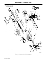
SECTION 7 − PARTS LIST 22. . . . . . . . . . . . . . . . . . . . . . . . . . . . . . . . . . . . . . . . . . . . . . . . . . . . . . . . . . . . . . . . . . . . .
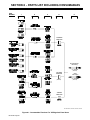
SECTION 8 − PARTS LIST INCLUDING CONSUMABLES 26. . . . . . . . . . . . . . . . . . . . . . . . . . . . . . . . . . . . . . . . .
WARRANTY


OM-236 297 Page 1
SECTION 1 −SAFETY PRECAUTIONS FOR GMAW
WELDING GUNS − READ BEFORE USING
SR7_2007−04
Protect yourself and others from injury — read and follow these precautions.
1-1. Symbol Usage
DANGER! − Indicates a hazardous situation which, if
not avoided, will result in death or serious injury. The
possible hazards are shown in the adjoining symbols
or explained in the text.
Indicates a hazardous situation which, if not avoided,
could result in death or serious injury. The possible
hazards are shown in the adjoining symbols or ex-
plained in the text.
NOTICE − Indicates statements not related to personal injury.
. Indicates special instructions.
This group of symbols means Warning! Watch Out! ELECTRIC
SHOCK, MOVING PARTS, and HOT PARTS hazards. Consult sym-
bols and related instructions below for necessary actions to avoid the
hazards.
1-2. Arc Welding Hazards
The symbols shown below are used throughout this manual
to call attention to and identify possible hazards. When you
see the symbol, watch out, and follow the related instructions
to avoid the hazard. The safety information given below is
only a summary of the more complete safety information
found in the welding power source Owner’s Manual. Read
and follow all Safety Standards.
Only qualified persons should install, operate, maintain, and
repair this unit.
During operation, keep everybody, especially children, away.
ELECTRIC SHOCK can kill.
D Always wear dry insulating gloves.
D Insulate yourself from work and ground.
D Do not touch live electrode or electrical parts.
D Repair or replace worn, damaged, or cracked gun or cable insula-
tion.
D Turn off welding power source before changing contact tip or gun
parts.
D Keep all covers and handle securely in place.
D Keep your head out of the fumes.
D Ventilate area, or use breathing device.
D Read Material Safety Data Sheets (MSDSs)
and manufacturer’s instructions for material
used.
FUMES AND GASES can be hazardous.
D Do not weld near flammable material.
D Do not weld on closed containers.
D Watch for fire; keep extinguisher nearby.
WELDING can cause fire or explosion.
BUILDUP OF GAS can injure or kill.
D Shut off shielding gas supply when not in use.
D Always ventilate confined spaces or use ap-
proved air-supplied respirator.
D Wear welding helmet with correct shade of fil-
ter.
D Wear correct eye and body protection.
D Cover exposed skin with spatter-resistant
clothing.
ARC RAYS can burn eyes and skin.
HOT PARTS can cause severe burns.
D Allow gun to cool before touching.
D Do not touch hot metal.
D Protect hot metal from contact by others.
NOISE can damage hearing.
Noise from some processes or equipment can
damage hearing.
D Check for noise level limits exceeding those
specified by OSHA.
D Use approved ear plugs or ear muffs if noise level is high.
D Warn others nearby about noise hazard.
WELDING WIRE can cause injury.
D Keep hands and body away from gun tip when
trigger is pressed.

OM-236 297 Page 2
1-3. EMF Information
Considerations About Welding And The Effects Of Low Frequency
Electric And Magnetic Fields
Welding current, as it flows through welding cables, will cause electro-
magnetic fields. There has been and still is some concern about such
fields. However, after examining more than 500 studies spanning 17
years of research, a special blue ribbon committee of the National
Research Council concluded that: “The body of evidence, in the
committee’s judgment, has not demonstrated that exposure to power-
frequency electric and magnetic fields is a human-health hazard.”
However, studies are still going forth and evidence continues to be
examined. Until the final conclusions of the research are reached, you
may wish to minimize your exposure to electromagnetic fields when
welding or cutting.
To reduce magnetic fields in the workplace, use the following
procedures:
1. Keep cables close together by twisting or taping them, or using a
cable cover.
2. Arrange cables to one side and away from the operator.
3. Do not coil or drape cables around your body.
4. Keep welding power source and cables as far away from
operator as practical.
5. Connect work clamp to workpiece as close to the weld as
possible.
About Implanted Medical Devices:
Implanted Medical Device wearers should consult their doctor and the
device manufacturer before performing or going near arc welding, spot
welding, gouging, plasma arc cutting, or induction heating operations.
If cleared by your doctor, then following the above procedures is recom-
mended.

OM-236 297 Page 3
SECTION 2 − INTRODUCTION
2-1. Gun Specifications
Specification Description
Input Voltage 30 Volts DC
Duty Cycle (Air-Cooled Models) At 200 Amperes, 100% Using Argon Or Argon Mixture Shielding Gas
At 250 Amperes, 60% Using Argon Or Argon Mixture Shielding Gas
Duty Cycle (Water-Cooled Models) At 400 Amperes, 100% Using Argon Or Argon Mixture Shielding Gas
Wire Size Range .030 Thru 1/16 in (0.8 Thru 1.6 mm) Aluminum Wire
.030 Thru .045 in (0.8 Thru 1.1 mm) Hard Or Cored Wire
Net Weight (Torch Only) XR-A (2.2 lbs)
XR-W (2.4 lbs)
2-2. Duty Cycle And Overheating
Duty Cycle is percentage of 10 min-
utes that unit can weld at rated load
without overheating.
NOTICE − Exceeding duty cycle
can damage unit and void warranty.
sduty1 5/95
6 Minutes Welding 4 Minutes Resting
Continuous Welding
Air-Cooled Models
Water-Cooled Models
100% Duty Cycle At 400 Amperes Using Argon
Continuous Welding
100% Duty Cycle At 200 Amperes Using Argon 60% Duty Cycle At 250 Amperes Using Argon

OM-236 297 Page 4
SECTION 3 − INSTALLATION
. Be sure that contact tip, liner, and drive rolls are correct for wire size and type. See Parts List to change parts as needed.
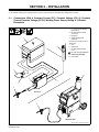
3-1. Connections With A Constant Current (CC), Constant Voltage (CV) Or Constant
Current/Constant Voltage (CC/CV) Welding Power Source Having A 14-Socket
Receptacle
Ref. 151 666-G / 804 542-B / 804 653-A
1 CC, CV Or CC/CV Welding
Power Source
2 24 VAC/Contactor Control
14-Pin Plug
3 Workpiece
4 Voltage Sensing Lead
(Optional)
Connect lead to workpiece for CC
welding only.
5 Gun
6 Wire Feeder
7 24 VAC/Contactor Control
Cord
! Do not use gas pressure
above 50 psi (345 kPa).
8 Gas Cylinder
1
2
3
4
5
7
8
6
Millermatic 350P
XR Control
1
8
5

OM-236 297 Page 5
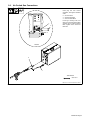
3-2. Air-Cooled Gun Connections
Ref. 801 577-A / 801 564-E / Ref. 151 666-G
1 Gun Control Cable
Insert plug into Gun Control
receptacle, and tighten threaded
collar.
2 Gun Connector
3 Gun Securing Knob
4 Gun Connector Block
Loosen gun securing knob, and
insert gun connector through Wire
opening until it bottoms against
block. Tighten knob. Close and
latch door.
Tools Needed:
9/16, 3/4 in
4
3
2
1
Left Side
2

OM-236 297 Page 6
3-3. Water-Cooled Gun Connections
Ref. 801 577-A / 805 107-A
. Turn on coolant supply before
welding or gun will be dam-
aged.
1 Gun Control Cable
Insert plug into Gun Control
receptacle, and tighten threaded
collar.
2 Gun Connector
3 Gun Securing Knob
4 Gun Connector Block
Loosen gun securing knob, and
insert gun connector through Wire
opening until it bottoms against
block. Tighten knob. Close and
latch door.
5 Gun (Coolant) “In” Hose
Connect to Water “In” fitting on
feeder (left-hand threads).
6 Gun (Coolant) “Out” Hose
Connect to Water “Out” fitting on
feeder (left-hand threads)
7 Water (Coolant) Output
8 Water (Coolant) Input
9 XR Control (Coolant) Output
10 XR Control (Coolant) Input
Close and latch door.
Tools Needed:
1
5
6
9/16 in
4
3
2
Left Side
7
8
9
10

OM-236 297 Page 7
3-4. Millermatic 350/350P Water Cooled Gun Connections
Ref. 804 945-A / 151 666-G
. Turn on coolant supply before welding
or gun will be damaged.
1 Coolant Supply
2 Millermatic 350P
3 Gun Control Cable
Insert plug into gun control receptacle and
tighten threaded collar.
4 Water In Hose
Connect to coolant supply with supplied
coupler and water hose (left-hand threads).
5 Gun Connector
Loosen gun securing knob, and insert gun
connector through Wire opening until it
bottoms against block. Tighten knob. Close
and latch door.
6 Water Out Hose
Connect to coolant supply with supplied
coupler and water hose (left-hand threads).
7 Coolant “In”
8 Coolant “Out”
Tools Needed:
5
9/16 in
6
4
3
1
2
8
7

OM-236 297 Page 8
3-5. Threading Welding Wire Through Millermatic 350/350P
1 Wire Spool
2 Welding Wire
3 Inlet Wire Guide
4 Drive Roll
5 Intermediate Wire Guide
6 Outlet Wire Guide
7 Pressure Adjustment Knob
8 Gun Conduit Cable
Lay gun cable out straight.
Tools Needed:
6 in
(150 mm)
. Hold wire tightly to keep it
from unraveling.
Open pressure assembly.
Pull and hold wire; cut off end.
Push wire thru guides into gun;
continue to hold wire.
Close and tighten pressure
assembly, and let go of wire.
. Set pressure indicator
scale to 1/2 lb.
Ref. 803 544-A / 218 243-A / 218 244-A / S-0627-A
1
2
3
4
Pressure
Indicator
Scale
218243-A
IMPORTANT!
For Aluminum Push-Pull welding.
Thread hub tension nut loosely
IMPORTANT!
For Aluminum
Push-Pull welding.
1
2
3
4
218244-A
7
8
35621 4
See Section 3-10 for threading weld-
ing wire through XR guns.
3/4 in
Tighten to
1/2 lb.

OM-236 297 Page 9
3-6. Threading Welding Wire Through XR-Control Feeder
Ref. 802 193-A / 801 577
Tools Needed:
2
1
1 Cable Assembly
Lay cable assembly out straight.
2 Jog Switch
Push Jog switch up to feed wire through
cable assembly.
3 Torque Switch
. Select proper push feeder torque set-
ting for wire size being used. Use low
torque for .030 in. (0.8mm) wire. Use
high torque for all other wire sizes.
3
. Hold wire tightly to keep
it from unraveling.
3-7. Adjusting Tension At Feeder
Ref. 802 193-A
Tools Needed:
Pull and hold wire; cut off end.
6 in
(150 mm)
Open tension arm.
Thread wire thru inlet guide, along drive roll groove, and
into wire conduit. Close tension arm. Adjust tension as
follows: grasp spool with one hand, press Jog switch, and
turn thumb nut clockwise until motor stalls when Jog
switch is pressed. Back thumb nut off slightly.
Proceed to Section 3-10.

OM-236 297 Page 10
3-8. 10-Pin Plug Information
10
Pin* Pin Information
E
F
D
J
G
C
I
H
B
A
A Electrode sense lead
B Motor Common
G Trigger
C Motor 0 to +24 volts DC with respect to pin B
D Trigger
E Wire speed Ref. +9 volts DC
H Wire speed com
F Wire speed 0 to +9 volts DC with respect to pin H
J Gun sensing resistor with respect to pin H
I Not used
3-9. Removing Top Cover Of Pistol Grip Gun
1 Top Cover Triangular Boss
Push up on triangular boss to open
door. Door hinges on handle.
To open door fully, push up on door
until it clicks into position.
. If door is pushed too far it will
separate from handle. If this
happens the door can be rein-
stalled.
Push door back into original posi-
tion to close.
802 528-C
1

OM-236 297 Page 11
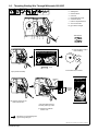
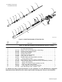
3-10. Threading Welding Wire Through Gun
Ref. 802 193-A / 801 556-B / 151 599-F
Tools Needed:
. Refer to Section 3-6 for instructions on feeding wire
through feeder.
Feed wire to check drive roll pressure.
If necessary, slightly tighten thumb nut
inside gun.
Cut off wire. Close and latch wire
feeder door.
WOOD
! Welding wire is electrically live when gun trigger
is used to jog wire.
. Turn OFF coolant supply before removing head tube
on water-cooled gun.
1 Pressure Roll Assembly
Lift arm and open pressure roll assembly.
2 Cable Assembly
Lay cable assembly out straight.
Push Jog switch up to feed wire through cable assembly.
3 Drive Roll
For wire sizes .035 in (0.9 mm) and smaller use small
groove, and .047 in (1.2 mm) and 1/16 in (1.6 mm) use
large groove.
4 Contact Tip
Manually thread wire along drive roll groove and out con-
tact tip 2 in (51 mm). Close pressure roll assembly.
5 Tension Thumbnut
6 Pressure Adjustment Knob
7 Final Pressure Adjustment
See procedure at bottom of page. Reinstall gun cover.
5
2
1
3
6
4

OM-236 297 Page 12
SECTION 4 − OPERATION
4-1. Gun Controls
1 Trigger
Press trigger to energize welding
power source contactor
(if applicable), start shielding gas
flow, and begin wire feed.
2 Wire Speed Control
Use control to fine adjust wire feed
speed set on wire feeder Weld
Speed control. The numbers
around the control are for reference
only.
1
2
Ref. 151 666-F
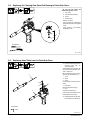
4-2. Shielding Gas
sb5.1 6/92 − S-0621-C / Ref. 151 666-F
1 Shielding Gas Cylinder
2 Valve
3 Gun Trigger
Open valve on cylinder just before
welding.
Gun trigger turns weld output and
gas flow on and off (see Section
4-1).
Close valve on cylinder when
finished welding.
1
2
3
4-3. Sequence Of Gas Metal Arc Welding (GMAW) − Continuous Or Spot
Begin Welding
ssb6.1* 9/92
Install &
Connect
Equipment
Put On
Personal Safety
Equipment
Set Controls
Turn On Gas
And Water (If
Applicable)
Turn On Feeder
And Welding
Power Source

OM-236 297 Page 13
4-4. Coolant Supply For Water-Cooled Models Only
Ref. 150 755-A
1 Coolant Supply
2 Coolant “In”
3 Coolant “Out”
See table below for coolant
guidelines.
Turn On coolant supply before
welding.
Turn Off coolant supply when
finished welding.
1
MILLER Low
Conductivity Coolant
No. 043 810**
MILLER Aluminum Protecting
Coolant No. 043 809**;
Distilled Or Deionized Water OK
Above 32° F (0° C)
GTAW Or Where
HF* Is Used
GMAW Or Where Coolant
Contacts Aluminum Parts Or
Where HF* Not Used
Application
*HF: High Frequency Current
**MILLER coolants protect to -37° F (-38°C) and resist algae growth.
Coolant
3
2

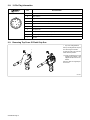
OM-236 297 Page 14
SECTION 5 − MAINTENANCE & TROUBLESHOOTING
. Maintain more often
during severe conditions.
! Disconnect power
before maintaining.
3 Months
Replace
Damaged Or
Unreadable
Labels
Replace
Damage
Gas Hose
Clean
And
Tighten
Weld
Terminals
Repair Or Replace
Cracked Cables
And Cords
6 Months
Blow Out Or
Vacuum Inside
Clean
Drive
Rolls

OM-236 297 Page 15
Ref. 151 599-F / Ref. 801 556-C / 801 564−E / Ref. 151 666-G / Ref. 200 371
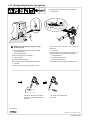
5-1. Replacing The Liner
! Turn Off wire feeder and
welding power source.
1 Drive Roll
2 Collet Nut
Lay gun cable out straight. Remove
drive roll on gun and collet nut on lin-
er tube assembly.
3 Gun Connector
Remove inlet guide from gun con-
nector, and remove old liner.
4 New Liner
Insert split end of new liner into gun
connector and continue feeding lin-
er through cable assembly until lin-
er is through liner tube assembly
and all of split portion is visible.
. If gun is a 15 ft (4.5 m) model,
push the split end of liner
through until the opposite end
is sticking out of the gun con-
nector 1 to 2 inches (2.5 to 5
cm). After trimming, the section
with the split on it can be saved
to use as another replacement
liner.
Cut off split portion of liner. Replace
collet nut with new nut from this kit.
Reinstall inlet guide at gun connec-
tor and tighten onto liner.
The liner end will not stick out of the
collet nut supplied with this kit.
At the gun connection end, cut liner
as close as possible to control
(push motor) drive rolls.
See Section 3-10 for instructions on
rethreading wire.
. It may be easier to replace the
collet nut with the liner conduit
removed from the gun housing
block.
Split End
1
Pistol Grip Gun
3
4
2

OM-236 297 Page 16
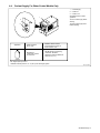
5-2. Changing Gun Contact Tip
Ref. 150 437-A
2
1
Remove nozzle
1 Nozzle
2 FasTip
Unscrew FasTip.
Install new FasTip.
5-3. Replacing Or Cleaning Gun Drive Roll In Pistol-Grip Guns
! Turn Off wire feeder and
welding power source.
1 Top Cover
2 Pressure Roll Assembly
Cut off wire where it enters
pressure roll assembly area.
3 Setscrew
4 Current Pick-Up Tab
This tab helps prevent burnback
caused by welding arcs inside the
contact tip. This tab may be re-
moved to provide an insulated drive
roll. (If tab is removed, a smaller di-
ameter contact tip is recom-
mended. See options in Parts List.)
Lightly grease top of tab before rein-
stalling.
5 Drive Roll
Use wire brush to clean drive roll.
Install drive roll with desired groove
down, and turn drive roll so one
setscrew faces flat side of shaft.
6 Bearing
7 Liner
Line up drive roll groove with bear-
ing groove and liner opening.
Tighten setscrews.
Thread welding wire through gun,
and adjust drive roll pressure, if
necessary (see Section 3-10).
Close and secure pressure roll
assembly. Reinstall top cover.
Ref. 151 599-F
Tools Needed:
5/64 in
2
67
1
5
3
4
Page is loading ...
Page is loading ...
Page is loading ...
Page is loading ...
Page is loading ...
Page is loading ...
Page is loading ...
Page is loading ...
Page is loading ...
Page is loading ...
Page is loading ...
Page is loading ...
Page is loading ...
Page is loading ...
Page is loading ...
Page is loading ...
-
 1
1
-
 2
2
-
 3
3
-
 4
4
-
 5
5
-
 6
6
-
 7
7
-
 8
8
-
 9
9
-
 10
10
-
 11
11
-
 12
12
-
 13
13
-
 14
14
-
 15
15
-
 16
16
-
 17
17
-
 18
18
-
 19
19
-
 20
20
-
 21
21
-
 22
22
-
 23
23
-
 24
24
-
 25
25
-
 26
26
-
 27
27
-
 28
28
-
 29
29
-
 30
30
-
 31
31
-
 32
32
-
 33
33
-
 34
34
-
 35
35
-
 36
36


Miller LK090392V Owner's manual
- Category
- Welding System
- Type
- Owner's manual
- This manual is also suitable for
Ask a question and I''ll find the answer in the document
Finding information in a document is now easier with AI
Related papers
-
Miller LJ250201V Owner's manual
-
-
-
-
-
-
-
-
-
Other documents
-
Miller Electric GA-17C Owner's manual
-
-
Hobart Welding Products OLYMPIC XRA A User manual
-
Westbrass 493144HRH-07 Operating instructions
-
-
-
-
Bernard DFB-OPPW Operating instructions
-
Python 248-8XX User manual
-