Page is loading ...

1
WARNING: To ensure that drive is not unexpectedly started,
turn off and lock out or tag power source before proceeding.
Failure to observe these precautions could result in bodily
injury.
FB Series Brake
INSTALLATION
STEP 1 — PRE-ASSEMBLY INSPECTION
All parts should be examined for any damage during the shipping
and handling process. Measurements should be taken to ensure
parts meet mounting requirements. All parts must be clean and
free of any foreign material before attempting assembly.
Prior to installing the FB brake, ensure that the shaft is square
with mounting plate so that the armature to magnet air gap may
be properly set.
STEP 2 — INSTALLATION OF KEY
Install key in shaft. Key should t keyseat with a tight t on the
sides and slight clearance over the key.
WARNING: Because of the possible danger to person(s) or
property from accidents which may result from the improper
use of products, it is important that correct procedures be
followed. Products must be used in accordance with the
engineering information specified in the catalog. Proper
installation, maintenance and operation procedures must
be observed. The instructions in the instruction manuals
must be followed. Inspections should be made as necessary
to assure safe operation under prevailing conditions. Proper
guards and other suitable safety devices or procedures as
may be desirable or as may be specified in safety codes
should be provided, and are neither provided by Baldor
Electric Company nor are the responsibility of Baldor
Electric Company. This unit and its associated equipment
must be installed, adjusted and maintained by qualified
personnel who are familiar with the construction and
operation of all equipment in the system and the potential
hazards involved. When risk to persons or property may be
involved, a holding device must be an integral part of the
driven equipment beyond the speed reducer output shaft.
INSTRUCTION MANUAL FOR DODGE
®
FB (Flange Mounted) SERIES POWER ON BRAKES
These instructions must be read thoroughly before installing or operating this product.
STEP 3 — BRAKE INSTALLATION
Mount the brake magnet using the 4 holes or slots in the
mounting ange. Concentricity between the brake mounting
pilot diameter and the shaft should be held to .010 inch T.I.R.
The FB17 and larger have an inside pilot diameter as well as an
outside pilot diameter. The brake ange should be bolted tightly
to the bulkhead as it is the reaction member for the brake torque.
STEP 4
Slide the armature hub onto the shaft. Do not force armature
as the armature springs may be damaged. Set armature so that
an airgap of .005 to .020 is between the armature and magnet.
Measure at four places around perimeter to ensure that air gap is
.005 to .020 . Tighten the two setscrews and recheck the airgap.
See recommended tightening torques in Table 1.
Table 1 - Recommended Tightening Torques
Set Screw Size
Recommended Tightening
Torque
(in. lb.)
#4 5.0
#5 9.5
#6 9.5
#8 19.4
#10 33.5
1/4” 78.0
STEP 5
Wire the two leads to the power supply. DODGE power supplies
are available with a wiring diagram showing the proper electrical
connections.
STEP 6
Burnish if desired. See Burnishing Procedures for details. FB
Series brakes are not supplied preburnished.
STEP 7
After unit has operated for a short period, recheck air gaps, drive
component mounting and setscrew torques.

2
BURNISHING PROCEDURE
Burnishing is a wearing-in or mating process of the friction
surfaces to ensure that the full rated torque will be obtained from
the brake. DODGE brakes will typically produce 50-90% of the
rated torque “out-of-the-box” without burnishing. The normal
slip that occurs when the load is engaged will self-burnish the
unit over time. Customers should decided if the “out-of-the-box”
torque is adequate for the application until the unit becomes
fully burnished. If full rated torque is required immediately, the
burnishing procedure listed below should be followed.
Care must be taken to prevent contamination of the friction faces
with oil or dirt particles during the burnishing process.
1. If possible, burnish units in their nal application or location
to ensure alignment of the mated parts.
2. If units cannot be burnished in nal application, mount units
in a test stand observing concentricity, alignment and air
gaps.
3. Using a ltered DC power supply, energize unit at 100%
of rated coil voltage for 5 seconds maximum (this assures
proper armature engagement against magnet assembly).
Then reduce voltage to 30%- 40% of rated coil voltage.
Table 2 - Static Torque
Unit
Size
Burnishing RPM
± 10%
Standard Static
Torque Rating
08 250 2.5 Inch-Lbs.
11 250 6 Inch-Lbs.
15 190 10 Inch-Lbs.
17 160 15 Inch-Lbs.
19 150 25 Inch-Lbs.
22 130 50 Inch-Lbs.
26 60 80 Inch-Lbs.
30 50 125 Inch-Lbs.
42 30 250 Inch-Lbs.
4. Rotate the brake armature at the suggested RPM (see Table
2), while holding the brake magnet stationary to obtain a
forced slip while the unit is energized.
5. De-energize the unit after a three (3) minute forced slip. Do
not prolong beyond a three (3) minute duration. Long burnish
time will cause excessive heat build-up at the friction faces
resulting in poor performance.
6. Measure the static (or break away) torque of the unit with
both friction members of the brake stationary, at rated unit
voltage.
7. Static torque should be at the rating shown in Table 2. If the
unit does not produce this rating, repeat steps 3, 4 and 5
after a cool down period of ve (5) minutes until unit comes
up to the rated torque.
Table 3 - Response Times
Series
Rated
Static
Torque
Lb.-in.
Torque Build-Up
Time-Milliseconds
Torque
Decay
Time MS
80% of
Rated
Torque
100% of
Rated
Torque
10% of
Rated
Torque
08 2.5 4.8 7. 5 6.6
11 6 7. 2 10.5 11
15 10 9 12 17
17 15 10 14 14
19 25 33 48 35
22 50 27 42 20
26 80 22 40 30
30 125 43 60 36
42 250 45 70 50
NOTES:
1. Torque decay time is dependent on the type of arc suppression
circuit used. Decay times shown in Table 3 assumes use of
a diode in parallel with the coil for arc suppression. If no arc
suppression is used, torque will decay almost instantly.
2. Actual response times depend on several factors such as
inertia being accelerated, speed, load torque, and type of
switching used.
3. Time to full torque can be shortened by using an overexcited
DC power supply intended for this purpose.
4. The time to full torque is also dependent on the voltage
supply. If the brake is underpowered (low voltage), a decrease
in torque will result. The brake should be sized based upon
the worst case voltage condition. The DC voltage supply
should be ltered full wave for highest efciency. Half wave
DC voltage will result in lower torque output.
UL and CSA
DODGE FB Series power-on brakes are UL Recognized (UR) as
well as CSA approved. All units will carry the appropriate markings.
Supporting documentation, if needed, is available upon request

3
Table 4 - Allowable Cycles / Minute*
Unit
Size
Inertia (Lb-in
2
)
RPM 5 10 50 1000
08
225 300 200 30 12
900 30 12 2 1
11
225
–
300 60 30
900 45 20 3 2
15
225
–
350 120 60
900 60 30 6 3
17
225
– –
150 100
900 80 40 7 4
19
225 200 120 20 8
900 9 5 1
–
22
225 250 150 25 10
900 12 6 1
–
26
225 300 200 30 12
900 20 9 2 1
30
225 350 250 40 20
900 25 12 3 1
42
225
–
300 60 30
900 30 20 4 2
*Table intended as a guide. For other speeds and inertias,
consult DODGE.
ARC SUPPRESSION
When the brake is de-energized, a reverse voltage is generated
in the coil. The reverse voltage can be very high and may cause
damage to the coil and switch in the circuit. To protect the coil
and switch the voltage should be suppressed using an arc
suppression circuit. Arc suppression does not affect the brake
engagement time.
RESISTOR / DIODE / ZENER DIODE –
NORMAL DISENGAGEMENT TIME
For most applications a resistor connected in parallel with the
brake coil is adequate. The resistor should be rated at six times
the coil resistance and approximately 25% of the coil wattage.
DC
DC
AC
AC
SWITCH
RESISTOR
CLUTCH
CAPACITOR OR METAL OXIDE VARISTOR
(MOV) FAST DISENGAGEMENT TIME
For applications requiring fast brake disengagement, a capacitor
or MOV connected in parallel with the break coil should be used.
DC
DC
AC
AC
SWITCH
RESISTOR
DIODES
CLUTCH
DIODE
SLOW DISENGAGEMENT TIME
For applications where a delayed disengagement is desired, a
diode should be used in parallel with the brake coil or switch the
A/C side of the circuit.
DC
DC
AC
AC
SWITCH
ZENER
CLUTCH
To eliminate the added current draw, a diode may be added as
shown below.
DC
DC
AC
AC
SWITCH
RESISTOR
CLUTCH
OR
BRAKE
+
-
For faster release use a zener diode with a rating two times the
coil voltage.
DC
DC
AC
AC
SWITCH
RESISTOR
CLUTCH
OR
BRAKE
+
-

World Headquarters
P.O. Box 2400, Fort Smith, AR 72902-2400 U.S.A., Ph: (1) 479.646.4711, Fax (1) 479.648.5792, International Fax (1) 479.648.5895
Dodge Product Support
6040 Ponders Court, Greenville, SC 29615-4617 U.S.A., Ph: (1) 864.297.4800, Fax: (1) 864.281.2433
www.baldor.com
All Rights Reserved. Printed in USA.
12/10 TROPHY 500
© Baldor Electric Company
MN4011 (Replaces 499749)
*4011-1210*
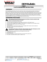
ARMATURE-HUB
ASSEMBLY
FRICTION
MATERIAL
FIELD
ASSEMBLY
MOUNTING
FLANGE
FB SERIES BRAKE
Brake Replacement Parts
Unit
Size
Part
No.
Volts
DC
Bore
In.
Field Assy.
Part No.
Armature
Hub Assy.
Part No.
FB08
025200
025201
90
3/16
1/4
025261
025290
025291
025202
025203
24
3/16
1/4
025363
025290
025291
FB11
025300
025301
90
1/4
5/16
025361
025391
025392
025302
025303
24
1/4
5/16
025363
025492
025493
FB15
025400
025401
90
5/16
3/8
025461
025492
025493
025402
025403
24
5/16
3/8
025363
025492
025493
FB17 025500
025501
90
5/16
3/8
025561
025494
025495
025502
025503
24
5/16
3/8
025663
025494
025495
FB19 025600
025601
90
3/8
1/2
025661
025693
025694
025602
025603
24
3/8
1/2
025663
025793
025794
FB22
025700
025701
90
3/8
1/2
025761
025793
025794
025702
025703
24
3/8
1/2
025763
025793
025794
FB26
025800
025801
90
1/2
5/8
025861
025894
025895
025802
025803
24
1/2
5/8
025863
025894
025895
FB 30
025900
025901
90
5/8
3/4
025961
025995
025996
025902
025903
24
5/8
3/4
025963
025995
025996
FB42
026000
026001
026004
026005
90
5/8
3/4
7/8
1
026061
026095
026096
026097
026098
026002
026003
026006
026007
24
5/8
3/4
7/8
1
026063
026005
026096
026097
026098
/