Page is loading ...

Introduction
The following is a little history of the original development of this unique and handsome aircraft. The Dornier Do 217 was a later
development of the original Do 17 series of bombers and reconnaissance aircraft. The prototype Do 17 first flew in 1938 and was
not especially successful. Never-the-less development continued and early pre-production Do 217A-O's undertook a variety of
clandestine photo-recon missions over the Soviet Union, prior to the German attack in 1941. Further development of the type
produced the E-2 variant, originally conceived as a divebomber. However trials proved this unpractical and the E-2 was
ultimately used for bombing raids over Great Britain and for antishipping missions over the North Sea and the Atlantic.

.
The Do 217J-1 variant was developed and used as a stopgap night fighter to counter the increasing number of bomber raids
over Germany in 1942. Modified from the E-2, the J-1 had a solid, non-glazed nose, bristling with four 20mm cannons and four
7.9mm machine guns.
This brings us to Spring 1943, when the Do 217N-2R22 variant went into production as a dedicated and heavily armed night
fighter. This aircraft retained the solid nose with the four cannon and four machine guns in place. But in addition, it also carried
another four 20mm cannons mounted in the top of fuselage, behind the canopy. These weapons fired upwards at a 70O forward
angle. This unusual armament system was used effectively against Allied bomber formations and was called "Schräge Musik".
Later versions also included the Lichtenstein SN
-
2 radar system, with its unique antenna array on the fuselage nose.
The SIG Do 217 is strictly a sport scale model and not necessarily based on any particular variant. Instead, we leaned on both
the J-1 and 2R22 night fighter versions of this airplane to create our own R/C version. If you desire, the SIG Do 217 lends itself
to a lot of details that would look great on this model.
The recent and rapid development of super-efficient electric motors and certainly lithium polymer batteries have both served to
make multi-engine models a very practical reality. Our prototype Do 217 models have proven to be outstanding R/C aircraft,
both in terms of performance and looks. We've flown our own prototypes a great deal and can report to you for sure that they
are solid flying models with surprisingly honest flying characteristics. When powered with a couple of appropriately sized
brushless outrunner motors, swinging the recommended prop sizes, the airplane will have a wide speed range and should be
capable of some very nice - although not necessarily scale - aerobatics. While the SIG Do 217 is a comfortable model to fly, we
do not recommend it as a first R/C model. But we can and do highly recommend the Do 217 as your first semi-scale twin
electric model!
This assembly manual will guide you through each construction phase in detail and is further enhanced with photos that visually
assist you with each step. It is important that you follow the construction sequence carefully and accurately to achieve the best
results.
Reference Material
"GERMAN AIRCRAFT of WORLD WAR II", Edited by David Donald, Published by Motorbooks International, Osceola, WI
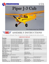
Kit Specifications: Imperial Metric
Wing Span 47 in. 1194 mm
Wing Area 324.6 sq. in. 20.9 dm2
Length 37.5 in. 953 mm
Flying Weight (typ) 30 - 35 oz. 850 - 990 g
Wing Loading 14.2 - 16 oz./sq. ft. 43.3 - 48.7 g/dm2
Motor (2 Required) 40 - 70 Watt Motors
Radio Equipment 4 Channels, (w/Mini Receiver & 3 or 4 Micro Servos)
Kit Number SIGRC99
Required Tools & Supplies
Glues - SIG Kwik-Set 5-Minute Epoxy, SIG-Bond Glue, SIG Thin, Medium and
Thick CA Glue
Loctite® Non-Permanent Thread Locker
Hobby Knife with Sharp #11 Blades
SIG AeroKote® or AeroKote-Lite®
Covering Tools - Heat Gun, Iron, Trim Seal Tool
Power Drill and hand "pin" vise (for smaller diameter drill bits as needed)
An assortment of drill bits and/or a numbered drill index
Soldering Iron and solder
-
STA
-
BRITE
®
Silver Solder suggested
Building Board
Modelers "T" pins
Waxed Paper
Sandpaper - assorted grits
Selection of Pliers
Selection of Screwdrivers
Razor Blades
Tweezers

.
COMPLETE KIT PARTS LIST
Balsa Sticks and Sheets
5 1/16"x3"x36" Balsa sheets for
wing sheeting
4 1/16"x2"x36" Balsa sheets for wing
sheeting
2 1/32"x3"x18" Balsa sheet for
stabilizer sheeting
2 1/16"x3/16"x36" Balsa sticks
for cap strips
2 1/4"x1/2"x24" Shaped balsa
leading edge
1 3/32"x1"x36" Balsa for fuselage 2 3/32"x1/4"x36" Balsa stabilizer
parts
2 1/8"x1/4"x36" Balsa for
assorted parts
2 1/4"x1/4"x36" Balsa for
assorted parts
1 5/16"x1-1/4"x24" Balsa tapered
trailing edge for ailerons
3 1/4"x1-3/4"x1-1/2" Balsa for
top front nose block
1 1-3/4"x1-3/4"x1" Balsa for
nose block
1 3/4"x1-3/4"x1-1/4" Balsa for
tail block
Laser Cut Balsa
2 1/16"x3"x24" Sheet #1 wing
ribs
1 1/16"x3"x24 Sheet #2 assorted
parts
1
3/32"x4"x36" Sheet #3 fuselage
parts
2 3/32"x3"x36" Sheet #4
fuselage sides
1 1/8"x3x36" Sheet #5 fuselage
parts
1 1/8"x3"x24" Sheet #6 fuselage parts 1 1/8"x3"x24" Sheet #7 assorted
parts
1 1/8"x4"x24" Sheet #8 nacelle
parts
1 1/8"x4"x24" Sheet #9 nacelle
sides
Laser Cut Plywood - Lite Ply
1 1/8"x4"x24" Sheet #10
assorted parts
1 1/8"x6"x16" Sheet #11 assorted
parts
Hardwood Parts
6 1/8"x3/16"x24" Spruce wing
spars and doublers
1 1/8" dia.x4" Dowel for hatch hold
down
1 3/16" dia.x2" Dowel for wing
hold down
Wire Parts
2 1/32"x36" Music wire for
pushrods
1 1/16"x3-1/2" Music wire for control
horn
1 .027"x6" Steel cable for rudder
pushrod
1 30" #20 wire Red electrical
cable for motor wiring
1 30" #20 wire Black electrical
cable for motor wiring
Hardware
1
1/16" I.D. wheel collar Elevator
horn
5 4-40x3/8" headless setscrew
Elevator horn & pushrod connectors
1 4-40 metal threaded RC link
Elevator horn
1 10-32 blind nut Wing hold down 16 #2x7/16" sheet metal screws,
socket head w/washer
2 2-56 metal threaded RC links
Aileron linkage
2 2-56 threaded steel rods
Aileron linkage
4 Pushrod connectors Control hook
ups
Miscellaneous Parts
1 1"x24" glass tape Wing center
section
1 Aileron interconnect horn Elevator
pushrod
1 Small control horn - right
Aileron linkage
1 Small control horn -
left Aileron
linkage
2 1/8"x24" Nylon tubes Pushrod
guides
1 10-32x1" Nylon bolt Wing hold down 7 Easy-hinges Control surfaces 1 3/32" O.D.x1-1/2" Brass tube
Solder couplings
2 Plastic cowls Vacuum formed
ABS
1 Clear canopy Vacuum formed
butyrate
1 SIGDKM299 Decal sheet 1 SIGRPIP299 Instrument Panel
1 Full sized plan 1 Assembly Manual
Key To Laser-Cut Parts
Use a pencil to identify each of the kit parts according to the following diagrams.
Note: When it is time to remove a part from its sheet, use a sharp #11 blade to slice through the small bridges that hold the part
to the sheet. Do not try to push the parts out of the sheet without first cutting through the bridges. Doing so may cause damage
to the part.
Construction Overview
Since the Do-217 kit is a somewhat more complex airplane, compared to typical sport models, the building sequence presented
in this manual should help to have the right part at the right time and cut down the time waiting for things to cure. Sort the sheet
wood and spars into separate stacks for the right and left wing, stabilizers, nacelles, and fuselage. Doing this ahead of time
helps to prevent using a piece of wood in the wrong place and then looking for it later when it is called for. To ease construction
where parts are to bend, some of the parts need to be preformed. This is easy to do but takes some time. These instructions will
tell you when to do this.

.

.

.
WING CONSTRUCTION
1.
Prepare the wing sheeting and spars.
Cut 4 spars from the
1/8"x3/16"x24" (3.2x4.8x610mm) spruce
23-1/8" (587.4mm) long.
Cut 4 spar doublers 7" (177.8mm) long
from the 36" (914 mm) long piece of the
same material.
Glue a doubler to the top of each spar
at one end then taper the last
2" (50.8mm) of the opposite end on the
bottom as shown.
2.
Cut the four trailing edge sheets from
the 1/16"x2" (1.5x50.8 mm) sheets 24"
long. Save the 12" (304.8mm) cut-offs
from the ends of these sheets for the
center sheeting.
Taper these from 2" (50.8mm) wide at
the root to 1-1/2" (38.1mm) wide at the
tip.
Taper the back edge of the sheet down
to about 1/64" (.4mm) over about
3/8" (9.5 mm). Make 2 top and 2 bottom
sheets.
3.
Cut the two leading edge sheets from
the 1/16"x3" (1.5x76.2mm) sheets
24" (609.6mm) long. Save the
12" (305mm) cut-offs from the ends for
the center sheeting. Taper these from
3" (76.2mm) wide at the root to 1-
3/4" (44.5mm) wide at the tip. Cut two
holes in each for the motor power wires
1" (25.4mm) forward of the spar and
1/2" (12.7mm) and 5" (127mm) from the
root. You can make a neat circle cutter
with a piece of 1/2" (12.7mm) brass
tube sharpened at the end.
4.
Cover the plan over the right wing panel with wax paper and pin the leading and
trailing edge sheets down to the plan in their proper place. Glue the W-12 piece
between them at the tip where shown. Place a 1/8" (3.2mm) shim under W-12
and the tip sheeting. Glue the bottom spar to the rear edge of the leading edge
sheet and pin down just outside of W-9. Make sure the doublers are towards the
center of the wing.
5.
Place ribs W-2 through W-
9 down on the spar making sure the ribs are vertical to
the sheeting. The W-1 rib is set with the top angled towards the tip slightly using
the dihedral gage to set the angle. Glue the ribs only to the trailing edge sheeting
and the spar for now.
6.
Fit and glue the top spar in place. Do not glue the spars together at the tip at this
time. Fit and glue the W-14 aileron spar to the trailing edge sheeting between W-
5 and W-9 and to the rear of ribs W6, 7, 8, and add the 1/8"x1/4" (3.2x6.4mm)
trailing edge doublers between ribs W-5 and W-6, next to W-7, and next to W-9.

.
7. Install the aileron servo mounting plate SM and it's brace SMB on the inboard
side of W-6 as shown on the plans. The bottom of this should be flush with the
building board.
8.
Starting at W-1 and working out to the tip, pull the leading edge sheeting up
against the bottom of the ribs and glue them to the ribs. Thin CA works great for
this operation, with the help of some accelerator.
9.
Get the shaped 1/4"x1/2" (6.4x12.7mm) shaped leading edge and glue it in place.
The angled edge should be on the bottom against the sheeting and the side
should be flush with the nose of the ribs.
10.
Fit and install the 1/8" (3mm) lite ply tip W-11. Taper the rear of W-11 in the
hatched area. The front of W-11 should touch the back of the leading edge and
W-9 and the trailing edge of this piece should just touch the tip of W-9 at the
trailing edge.
Now glue the top spar to the W-11 wing tip. When dry cut the trailing edge
sheeting out where the aileron will go in.
11.
Shape the top of the aileron spar until it matches the tops of the ribs.
12.
Glue one of the pre-shaped trailing edge sheets to the ribs and along the trailing
edge and to the tip outline. To allow working time here it is best to use SIG-Bond
glue to hold the top sheeting to the ribs and spars.
Be sure to pin the sheets down securely while the glue dries.
13.
Taper the other two top leading edge
sheeting from 2-3/4" (69.9mm) at the
root to 1-1/2" (38.1mm) at the tip.
True up and bevel the front edge of this
sheet so it is a perfect match to the rear
of the leading edge.
14.
Spread SIG-Bond on the ribs and spar
then use thin CA to attach the sheeting
to the leading edge at an angle that
matches the front of the ribs. Now pull
the rear of the sheeting down to the ribs
and pin in place until the glue dries. If
you have trouble getting the sheet to
conform you can give it a spray of water
on the outside to help it follow the curve
of the ribs.
15.
Trim and add the curved W-12 to the top of the tip between the sheets.

.
16.
Plank the upper center section of the wings. Prepare the center section sheeting as shown in drawings. Fit the front piece
first then cut the rear to fit in the remaining space. A neat trick to get the radius in the corner of the sheets is to trace around
a quarter.
17.
Add the 1/16"x3/16" (1.5x4.8mm) cap strips on the top of the remaining ribs.
18.
You can now remove this wing panel from the building board, cut away the
sheeting from the aileron area, rough shape the leading edge, trim the excess
sheeting from the tip and true up the sheeting at the root rib.
19.
Set this panel aside and build the other panel using steps #1 through #18.
20
Make the servo wire guide tubes by
rolling a 2"x11" (50.8x279.4mm) piece
of typing paper tightly around a section
of 3/8" (9.5 mm) dowel then insert this
dowel and paper into the holes.
21.
When the tube is in position, withdraw
the dowel and let the paper unwind in
the holes. Tack-glue the tubes in the
ribs to keep them from shifting.
Trim the inside end of the tube at an angle to ease the insertion of the servo wires.

.
NOTE: We highly recommends that you use a speed control for each motor and place each control in the nacelle behind
the motor. For this you will need to also cut a hole in the bottom of the tube just inboard of F-3 for the receiver lead of the
speed control.
22
Feed motor wires through the hole in the leading edge sheeting next to W-1, through the front hole in rib W-2 and out the
hole just short of rib W
-
3. Tape the wires together to keep them from slipping out. (refer to photo 23)
23.
The two wing halves are now joined. Place the wing halves upside down on your
work surface with their root ribs facing each other. Use lengths of balsa stock to
shim the leading and trailing edges of the wing panels, supporting them so that
their top wing spars are flat to the work surface. Make sure the root ribs are flush
to each other. Cut two pieces of the 1/8"x3/16" (3.2x4.8mm) spruce spar material
5" (127mm) long for the spar joiners. Insert the joiner for the top spar in one side
and glue to the spar and the top skin.
24.
Using 30-
minute epoxy, spread a thin coat of glue on the root rib of the other wing
and on the spar joiner that extends from the first panel. Slide the two halves
together and run a strip of masking tape over the seam on the top of the wing to
hold it together and to contain any epoxy that tries to seep out. Now lay the wing
up side down with the spars flat on the building board and tape the leading edge
and trailing edge securely together so the panels line up exactly. Glue in the
bottom spar joiner and clean up any excess epoxy with a paper towel and alcohol
then set aside to cure.
25.
While waiting for this to cure, prepare the center sheeting for use. Cut the two
1/2" (12.7mm) holes for the servo wires in the front sheets on a centerline
1/2" (12.7mm) back from the leading edge and 1/2" (127 mm) and 5" (127mm)
out from the center and glue these sheets onto the bottom center section, behind
the leading edge sheeting. (Refer to drawings at step #16)
26.
You can now remove all the tape and finish shaping and sanding the wing.
27.
Glue the 1" (25.4mm) fiberglass tape over the center joint of the wing top and
bottom. Medium CA works well for this application. Rub in a second coat of glue
and let cure before sanding out any lumps.
28.
To shape the ailerons cut the 1-1/4"x5/16"x24" (31.7x7.9x609.6mm) piece of trailing edge stock into two 10-
1/2" (266.7mm) sections. At one end of each piece measure up 7/8" (22.2mm) from the trailing edge and make a mark.
Draw a line with a straight edge from this mark to the corner at the thick side at the other end. Cut this triangular piece off
and sand smooth. Draw a centerline down the thick edge of the aileron and bevel down to the line from top and bottom.
Now fit the aileron to the cutout at the trailing edge of the wing allowing 1/32" (.8mm) gap at each end. Mark each aileron
for left and right.

.
FUSELAGE CONSTRUCTION
To make the assembly of the nacelle and fuselage assembly quicker and more efficient, pre-form the following parts so
they can be drying while the stabilizer and rudders are built.
29.
Secure parts numbered N
-
4 (4 pcs.), N
-
5 (4 pcs.), and N
-
6 (2 pcs.) from their laser cut sheets #8 and #9.
30.
Prepare a soaking solution of 1
-
cup hot water and 1 cup ammonia and pour into a small plastic tub or coffee can.
31.
Soak the rear 2/3’s of the N-4's and the
front 2/3's of pieces N-5 and N-6 in this
solution for an hour, remove and pat
dry.
32.
Shim and weight the pieces as shown
with 3/4" and 1/2" (20 and 12.7mm)
shims and allow them to dry for a day.
Make sure you bend 2 rights and two
lefts of N-4 and N-6
33.
Get the two F-13 fuselage bottom pieces from the 1/16" (1.5mm) sheet #2 and the two F-
22s from the 3/32" (2.4mm) sheet
#3. These need to be preformed before being glued to the fuselage. Soak them in warm water as before then weigh them
down with 3/4" (20mm) shims at each end. The weight should be applied about 2/3’s of the way towards the small end of
the F
-
13's and the curved end of the F
-
22's. Make sure you make a left and right when doing the F
-
22's.
TAIL SURFACE CONSTRUCTION
34.
Cut 8 rib blanks 2-1/4" (57.1mm) long from 3/32"x1/4" (2.4x6.4mm) balsa and 2 end ribs 1-7/8" (47.6mm) long from
1/4" (6.4mm) square. Stack these up side by side with one of the 1/4" (6.4mm) end ribs on the outside of the stack. Align
one end against a straight edge, square up the stack, and tape together tightly. True up the squared end with a sanding
block then measure 3/8" (9.5mm) in from this end and make a mark, then mark the center 1/8" (3.2mm) in from the edge.
Also mark the top of this stack as
shown.
35.
With a 1/8" (3.2mm) bit, drill through the
stack at this mark keeping the drill
centered all the way through. If you
have a drill press with a vice, it makes
this job easier. Elongate the holes in the
end ribs into a 1/4" (6.4mm) slot.
36.
Cover the stabilizer plan with wax paper
then pin down the 1/4" (6.4mm) square
leading and trailing edges over the plan.
37.
Cut to length and glue in the ribs where
shown on the plan keeping the hole to
the rear and the marked side up.
Glue a piece of 1/8"x1/4" (3.2x6.4mm)
balsa between the center two ribs at the
trailing edge.

.
38. Cut two 3/8" (9.5 mm) from the end of
each 1/8" (3.2 mm) pushrod tubes and
insert these as pushrod bushings in the
ribs in the four places shown on the
plan.
Slide a piece of 1/32" (.8 mm) music
wire through the holes and bushings
and align the bushings so the wire
slides freely from side to side before
gluing the bushings in.
39.
Remove the pins, sand the top of the stabilizer frame to get it level, then apply the 1/32" (.8mm) sheeting to the exposed
side. When dry, remove from board, and trim excess sheeting.
40.
Use a 1/8" dia. (3.2mm) bit to drill through the bottom of the leading edge, as
shown on the plans, to allow the rudder pushrod guide to pass through.
41.
Form the pushrod guide tube using a heat gun. This is easy to do if you insert a
toothpick or small bamboo skewer stick in one end then apply bending pressure
to the end of the tube as you carefully heat it with a heat gun in the bend area. As
the plastic heats up you will feel the resistance decrease. Keep the pressure on
until you can get it to bend 180 deg. without kinking as shown in the picture. Hold
in this position until it cools. When the pressure is released it will spring open and
you should have a nice tight 90 deg. bend, without kinks.
42.
Trim the tube to length and check to make sure the .027" (68mm) cable slides
easily through the tube. Hint: The cable will slide easier if you pre bend it to the
rough shape of the tube. When satisfied with the fit, glue the tube in as shown.
You will need to elongate the hole in the rib where the tube goes through next to
the wire.
43.
Get the 3/32"x1-1/2" brass tube from the hardware bag and cut it into four equal
sections. This can be easily done by rolling the tubing on a hard surface while
applying pressure with a sharp knife on the cut line.
44.
Slide the 1/32" dia. x16" (.8x406mm) music wire pushrod into the stab. Pass it
through the 3/32" (2.4mm) brass tube solder sleeve in the bay where the wire
and cable are soldered together and on out the other side until the wire is
centered.
45.
Slip the cable into the sleeve with the wire and adjust until the sleeve is about
half way between the rib bushing and the cable tube. Slip a scrap piece of balsa
wood between the sleeve and the bottom skin to protect the skin.
Now solder this assembly together using STA-BRITE® silver solder and flux.
When cool remove the scrap of wood and check for freedom of motion.
46.
Sand the bottom flat and glue on the
bottom 1/32"(.8mm) skin then trim.
Round off the leading edge.
47.
Cut and pin down the 1/4" (6.4 mm)
square elevator leading edges and the
3/32"x1/4" (3.7x6.4 mm) trailing edges.
Cut to length and glue in the
3/32"x1/4" (3.7x6.4mm) ribs leaving
them full depth for now. Glue the SG
gussets in the inner corners as shown.

.
48.
Remove the elevators from the plan, sand them to the tapered shape and bevel the leading edge.
49.
To make the elevator joiner and control horn, you will need the 3-1/2" (88.9mm) piece of 1/16" (1.5mm) music wire, the
1/16" (1.5mm) I.D. wheel collar, the 4-40 headless set screw, and the 4-40 RC link from the hardware bag.
Mark the exact center of the wire and file a slight flat there. Slide the 1/16" wheel collar onto the wire until the setscrew is
positioned directly over the flat, put a drop of Loctite® thread locker or medium CA in the set screw hole and tighten the
screw tight against the flat.
50.
Put a drop of Loctite® or medium CA on the set screw threads and screw the 4-40 RC link down on the setscrew until it
contacts the wheel collar.
It is important that when the glue sets that the pin in the RC link is parallel to the music wire.
51.
Measure out 1" (25.4mm) from each side of the wheel collar on each side and mark. Bend the wire 90 deg. at each mark
making sure the bends are 90 deg. from the control horn and parallel to each other.
52.
Mark the center of the bottom of the stabilizer at the trailing edge then make a mark 1/8" (3.2mm) either side of the center
mark. Saw 1/8" (3.2mm) deep at each mark and remove the wood in between. This provides clearance for the wheel collar
on the control horn.
53.
To mark where to drill the elevators for
the control horns, pin the elevators to the
stabilizer with the outboard ends about
1/16" (1.5mm) in from the rudders.
Lay the control horn over the elevators
with the collar centered in the notch and
mark where the wires need to enter the
elevators.
54.
Remove the elevators and drill with a 1/16" (1.5 mm) bit where you have marked.
Cut a 1/16" wide and 1/16" (1.5 x 1.5mm) deep groove from the drilled hole to the
inside end of the elevator. Trial-fit the elevator horn into the elevators and make
any adjustments needed to get the wire to lay flush with the elevator leading edge
and the elevator leading edge to match the stabilizer trailing edge.
55.
Place pieces of wax paper on the stabilizer where the horn will contact it. Use 5-
minute epoxy or thick CA to glue the horn into the elevators and then pin up
against the stab to hold everything in alignment while the glue sets.
56.
On a piece of wax paper glue the RUTs to the top of the RUs then sand smooth and round the edges. Smooth and round
the VSs also and layout the lines where they will glue onto the ends of the stabilizer.
Drill and slot to match the rudder pushrod exits in the end ribs.

.
NACELLE SURFACE CONSTRUCTION
The nacelles are built similar to the fuselage and you can use them to master the shaping technique that will be used on the
fuselage later.
57.
Taper the last 3/8" (9.5mm) of the inside rear of each nacelle side.
58.
Insert N-1 and N-2 between a right and left side and use a rubber band to hold
then together.
59.
Place this assembly on a flat surface with N-1 facing down. If you are using CA
glue this should be done on a piece of wax paper. Square the sides to the work
surface and glue this assembly together.
60.
Insert N-3 into the proper slots on the inside of the nacelle sides, pull the rear of
the sides together, and glue them together.
61.
Center the wide end of N-6 on the bottom flat of N-1 so that it overhangs the front about 1/16" (1.5 mm), align the rear of F-
6 with the rear of the nacelle and glue into position.
62.
To add the N-5 bottom corner pieces, it is now necessary to bevel the edges of
the sides and bottom to match the angles on the bottom of the bulkheads as
shown.
63.
Glue the preformed N-5's to the bottom corners of the nacelle.
64.
Round off the bottom of the nacelle now by first sanding the edges of the N-5
down flush with the sides and bottom. Now round off the remaining corners to
obtain a well-
rounded shape. The tops of the nacelles will be finished off after they
are mounted on the wing.
65.
Repeat these steps for the remaining nacelle.
NOTE: Now is the time to decide if you want to install landing gear. If you choose this option, refer to the optional landing
gear drawing below. If you choose to build this model without the optional landing gear, proceed to next step.

.
Optional Main Landing Gear
Parts Required (not furnished)
2 - SIGSH596 Nose Wheel Strut
2 - SIGSH523 1/8" Landing Gear Clips
1 pair - KAV0098 2" Wheels
1 pkg. - SIGSH586 1/8" Wheel Collars
Assembly Sequence
1. Build nacelles through to step 65.
2. Cut out 2 gear mounting plates from hard plywood.
3. Drill holes at the locations shown on the drawing.
4. Bend the gear strut as shown and screw it to the mounting
plate using SIGSH523 Landing Gear Clips.
5. Cut opening in the bottom of the nacelle to clear the coil
spring.
6. Glue the gear strut assembly to the back of N-2.
FUSELAGE CONSTRUCTION
66.
Locate and remove both fuselage sides from the two #4 sheets and mark a left
and right side.
67.
Using bulkhead F-4 in its slot on both fuselage sides at the leading edge of the
wing as a guide, draw a line to the top of the fuselage at the front of the bulkhead.
This line locates the joint between F-11 and F-12.
68.
Do the same with F-8 in its slot at the tail end. This locates the front of the
1/8"x1/4" (3.2x6.4mm) balsa stabilizer braces.

.
69.
Glue on F-11, F-12, and the 1/4" (6.4
mm) square parts at the nose.
70.
Glue in the 1/8"x1/4 " (3.2x6.4mm)
stabilizer supports.
71.
Glue in the 1/4" (6.4mm) square balsa
wing hold down plate supports ahead of
F-6 and below F-12.
72.
Locate bulkheads F
-
4, F
-
5, and F
-
6 and glue onto one fuselage side, making sure they are perpendicular to the side.
73.
Glue the other side to these bulkheads.
74.
Glue the 3 F-20s together then glue
them onto the 1/4" (6.4mm) square
wing hold down supports and F
-6. This
will help hold the fuselage square for
the following steps.
75.
Insert and glue in F-3, F-2, and F-1 in
that order.
76.
Glue in F-7 making sure the pushrod guide hole nearest the top of the fuselage is closest to the right side when looking
towards the front.
77.
Glue in F-8 making sure the top
pushrod guide hole is to the right as in
the previous step.
78.
Glue in F-9 making sure the pushrod
guide hole is offset to the left, and then
add F-10.
79.
Double check the fuselage for
straightness at this point, then go back
and double glue all your bulkheads to
the fuse sides.
80.
Install the two 1/8" (3.2mm) nylon pushrod guide tubes. Sand the bottoms of F-1, F-2, and F-3 to an angle to match the
curvature of the F
-
16 bottom sheeting.
81.
Notice the notch at the rear of F-13. This notch engages the tab on the bottom of
F-5. Glue an F-13 to F-5 and F-4, making sure that the front of F-13 centers on F-
1. When these are dry glue to F-3, F-2, and F-1.
82.
Laminate the second F-13 on top of the one that is glued to the formers.
NOTE: If you are installing landing gear, now is the time to make provisions for
the tail wheel. Refer to the drawing below. If you are not adding landing gear to
your model, proceed to the next step.

.
Optional Tail Wheel Installation
Parts Required (not furnished)
1 - 1/32" Dia. x18" Music Wire
1 - 1/8" O.D. x18" Plastic Tube
1 - 1/16" Dia. x3-1/4" Music Wire
1 - SIGSH132 Tailwheel Bracket
2 - #4x1/2" Sheet Metal Screws
1 - 1/16" I.D. Wheel Collar
1 - 3/4" Dia. Tailwheel
1 - 1/32"x3/16"x1/2" Brass Strip Stock
1 - 1/8"x1-1/2"x2-1/2" Lite-Ply
2 - 1/4"x2-1/2" Balsa Triangular Stock
83.
Glue F-24 on the bottom of the rear
fuselage.
84.
Glue F-18 to the top aft of the wing.
85.
Bevel all the corners on the top of the
fuselage from the wing to the tail and the
bottom of the fuselage like you did on the
bottom of the nacelles.
86.
Glue the F-22's to the lower nose section
starting from F-5 and working forward.
Sand the edges of the F-22's flush with
the F-13's then laminate the F-14 through
F-18 over them. Taper the back edge of
F-18 to fair into F-24.

.
87.
Glue the F
-
23's to the lower rear fuse from F
-
5 back.
88.
With the 3/32"x1" (2.4x25.4mm) balsa strips glue the top rear corners in from F
-
6 to the tail.
89.
Sand the top of the fuselage so that the sides between F
-
1 and F
-
2 are perfectly flat.
90.
Fit the 1/4"x1-3/4"x1-1/2"(6.4x44.5x 38.1mm) balsa piece on the top of the nose from F-1 back to the rear of F-2 and glue
in. Now sand the front and back of this block until it matches F-1 and F-2.
91.
Trace the nose block and tail block outlines from the plans onto a sheet of paper, cut them out, and glue them on the proper
blocks with a glue stick. The glue stick will hold them while you saw the blocks to the outline then they will peel off easily.
Tip: When cutting out the blocks. Cut them about 1/32" (.8mm) oversize. It is a lot easier to sand off a little excess than to
try to add wood later.
92.
Glue the blocks on the fuselage in their proper places.
93.
Glue F-3T to the fuselage side at the rear of the hatch area. The angle of the bulkhead should match the angle on the
fuselage sides and the corners that meet the sides should be flush with the top of F
-
11.
94.
Bevel the bottom of the F-25s to match the top surface of the sides between F-3T and F-4 and glue these pieces onto the
bulkheads. Sand the front and rear of the F-25 flush with the bulkheads, then sand the tops of them down, flush with the
tops of the bulkheads.
95.
Glue the 1/4"x1-3/4"x1-1/2" (6.4x44.5x38.1mm) block on the top of this section.
96.
Remove excess wood then round off the fuselage, as you did the nacelles.
97.
Join HB-1 and HB-2 on a flat surface.
98.
Sand the top of the fuselage in the hatch area until it is perfectly flat and the top
blocks behind F-3T and ahead of F-2 flush with the bulkheads. Tape a piece of
wax paper over the hatch area then pin the HB pieces down over the wax paper.
This forms the base of the battery hatch and cockpit.
99.
Bevel the bottom of HR so it makes a good joint with HB-2 and glue it on the rear
of the hatch so it lays flush against F-3T.

.
100.
Glue HF to the front of the hatch, centered on F
-
2.
101.
There are four HS's on sheet #6. Bevel the bottom of one of these to sit flush on the hatch bottom and snug against F-3T.
Now do the same for the other side.
102.
Laminate the other two HS's to the outside of the two that are glued down in the same way.
103.
While the hatch is still pinned in place drill a hole with a 1/8" (3.2mm) bit through the hole in the front of HF through former
H
-
2.
104.
Remove the hatch from the fuselage and glue a 3/8" (9.5 mm) piece of 1/8" (3.2mm) dowel into the front of the hatch so that
about 3/16" (4.8mm) sticks out the front.
105.
Sand a flat area on the top front part of the hatch sides and glue down the 1/4"x1-3/4"x1-1/2" (6.4x44.5x38.1mm) top block.
Sand this part flush with the front of the hatch and the instrument panel in the rear then glue in HP.
106.
Pin the hatch assembly back onto the fuselage and rough shape the nose back to the wing opening.
AIRFRAME ASSEMBLY
107.
Sand a 2" (50.8mm) wide flat at the
trailing edge and leading edge in the
center of the wing. This will allow F-
4T to
slip between F-
4 and the leading edge of
the wing. Mark the exact center of F-6
and F-4. See Drawing.
108.
Fit wing onto the fuselage lining the
centerline of the wing up to the centers
you marked on the bulkheads and to
make sure there is room for F-4T at the
leading edge.
109.
Glue the 3/16" (4.8mm) dowel into the
hole in F-4T so that 1/4" (6.4mm)
protrudes from the front, then cut the
dowel on the backside off flush with the
bulkhead.

.
110. Trial fit F-4T and dowel into place on F-4 making sure F-4T and F-4 are flush to each other. Remove F-4T, lay a sheet of
waxed paper between it and F
-4 in the wing saddle and replace F-4T.
111.
Place the wing back into the wing saddle making sure the flat at the leading edge
of the wing is flush with F-4T and the centerlines are in position. Tack-glue the
wing to F
-4T being careful not to allow excess glue to seep between the
bulkheads and the dowel.
112.
When dry remove the wing and finish gluing F-4T to the leading edge. For extra
strength glue a 1-1/2" (38.1mm) piece of fiberglass tape in the joint between the
bottom of F-4T and the bottom of the leading edge.
113.
Place the wing back on the fuse and check the fit.You may have to relieve the trailing edge a little to allow the wing to seat
in the saddle. Check the fit of F-6T against F-6 and the top of the wing. The edges of F-6T should match F-
6 when sitting on
top of the wing.
114.
Remove the wing and place a piece of wax paper under the trailing edge and up F-6. Slip a 1/32" (.8mm) shim between the
waxed paper and F
-6 to position F-6T properly, replace the wing then glue F-6T onto the trailing edge of the wing. You
should now be able to remove and insert the wing without difficulty.
115.
Glue a 3/16"x1/4" (4.8x6.4mm) balsa shim on the wing bolt platform, W-
13, sand a
slight flat on the bottom as shown on cross section W-1 on the plans, then glue
this to the wing and F-6T in the center.
116.
Center wing on the fuselage and drill perpendicular to W-13 through the pre-cut
hole all the way through the wing and the F-20 plate in the fuselage with a
13/64" (5.3mm) bit.
117.
Remove the wing and enlarge the hole in the fuselage plate to 1/4" (6.4mm). Using a 10-32 bolt and washers pull the 10-32
blind nut into the mounting plate and glue. If any of the blind nut protrudes above the plate, file or grind it off flush and clean
the threads.
118.
Layout the position of the sides of the
wing trailing edge fuselage fairing.
Measure 2-1/8" (54mm) forward from F-
6T on the centerline and make a mark.
Then measure 1" (25.4mm) off to each
side of the centerline and mark as
shown. Fit the two WFSs to the top
surface of the wing and glue them down
to the sides of F-6T and with the tips
centered on the marks.

.
119. Taper the rounded end of the WFT top
so it blends into the top of the wing and
glue it onto the top of F-6T and onto the
centerline of the wing.
120.
Sand a 45 deg. angle along the sides of
WFT to match former F
-
6T.
121.
Fit and glue the WFC pieces onto the
corners of the fairing by beveling the
bottom to match the top of WFS and the
wing skin.
122.
Lay strips of masking tape along the sides of the WFSs to protect the wing skin and sand the excess off the top of the
WFCs.
123.
Run the 13/64" (5.3mm) drill back through the hole for the bolt and through the top of the fairing piece to mark the location
of the wing hold down bolt. Install guide tube now, if desired.
124.
Sand the fairing pieces flush to the rear
of F-6T and bolt the wing onto the
fuselage again. Now shape the fairing to
blend into the rear of the fuselage.
125.
With scraps of 1/8"(3.2mm) balsa from
the laser cut sheets fill between F-4T
and the top of the wing and blend into
the front of the fuselage over F-4 up to
F-3T.
This completes the basic shaping of the wing and fuselage joint and now it is time to add the nacelles.
126.
Install the servo wires for the speed controls and aileron servos at this time. You will need two 12" extensions for the speed
controls and two for the aileron servos. Tie the plugs together in the center of the wing at the ends of a 6" piece of string to
make sure you don't pull them up into the wing by mistake, while working on the nacelles.
127.
On the bottom of the wing measure out 5-9/16" (141.3mm) from the centerline at both the leading edge and trailing edge
and extend these marks until they are visible from the top of the wing. These are the centerlines that the nacelles are
mounted on. From the nacelle centerline at the leading edge of each wing measure 1/4" (6.4mm) towards the wing tip and
make a mark. From this mark measure 1-1/2" (38.1mm) towards the center of the wing and cut into the front of the leading
edge at this mark 3/32" (2.4mm) deep.
See Drawing.
Remove a tapered piece from the
leading edge from the outboard mark to
the bottom of this cut. This gives a flat
spot on the leading edge for the top of
N
-
2 to glue to.
/