Page is loading ...

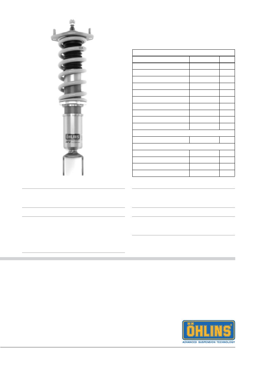
Shock Absorber Kit for Honda S2000 (AP1 , AP2)
HOS MI20 FRONT
Mounting Instructions
Note!1
Please note that there can be small differences
between your product and the images in
these instructions.
Note!1
Please note that during storage and transport,
especially at high ambient temperature, some
of the oil and grease used for assembly may
leak and stain the packaging. This will not cause
damage to the product, wipe off the excessive
oil or grease with a cloth.
Note!1
Before you install this product, check the kit
contents. If anything is missing, please contact
an Öhlins dealer.
Warning!⚠
Before you install this product, read the Öhlins
Owner’s manual. This product is an important
part of the vehicle and the vehicle stability.
Kit Contents
Description Part No Pcs
Shock absorber 2
Dust Boot 10216-01 2
Top mount 25633-35 2
Spring 2
Lock nut M10 24627-01 2
Flange nut 24618-03 2
Bolt M6 24628-02 2
Nut M6 24626-03 2
Bearing spacer 25633-35 4
Lower spring seat 24635-03 2
Lock nut 24636-03 4
Mounted on shock absorber
Adjuster 24631-04 2
Used for both front and rear
C-spanner 1
C-spanner 1
Öhlins sticker 1
Öhlins Owner´s Manual 1
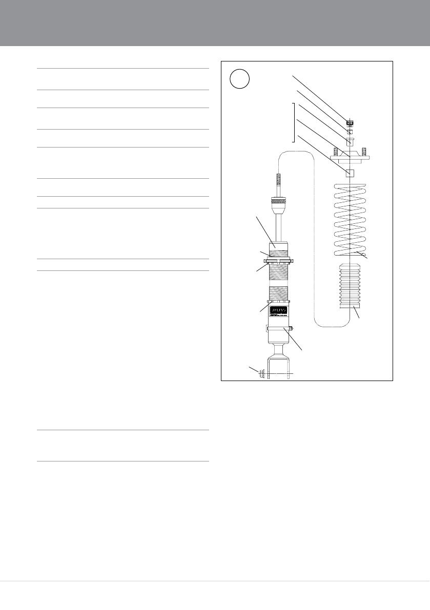
2
/RFNQXW
6SULQJ
%HDULQJVSDFHU
/RFNQXW0
7RSPRXQW
'XVWERRW
6KRFN
DEVRUEHU
/RFNQXW
%HDULQJVSDFHU
$GMXVWPHQW
NQRE
%UDNHKRVHEUDFNHW
Lower
spring seat
/RFNQXW
0
1
Raise the vehicle and put it on jack stands.
Warning!⚠
Ensure that it is securely supported.
2
Remove the front wheels.
3
Remove the lower and the upper attachments
and remove the original shock absorbers.
4
Tighten the lower spring seat and the lock nut
to 50 - 60 Nm.
Fit the the dust boot, the spring, the top mount
and the adjuster according to g 1. Tighten the
nylon nut to 20 Nm.
Note!1
When tightening the top mount nut, the shock
absorber shaft must be held in position with a
5 mm Allen key.
5
Install the Öhlins shock absorbers on the
vehicle.
6
Fasten the upper attachments.
MOUNTING INSTRUCTIONS
Warning!⚠
We strongly recommend to let an Öhlins dealer
install this product.
Warning!⚠
If you work with a lifted vehicle, make sure that it
is safely supported to prevent it from tipping over.
Note!1
When you work with this product, see the
vehicle service manual for vehicle specic
procedures and important data.
Note!1
Before you install this product clean the vehicle.
1

3
MOUNTING INSTRUCTIONS
Note!1
Make sure that all bolts are tightened to the
correct torque and that nothing fouls or restricts
movement of the shock absorber when it is
being fully compressed or extended.
7
Mount the brake hose to the brake hose
bracket on the Ohlins damper. Use the
supplied M6 bolt and nut. Tighten the nut to
6 Nm according to g 2.
8
Make sure that all removed parts are
reinstalled in the same way as they were
before the installation of the Öhlins shock
absorber.
2
%ROW0
1XW0
%UDNHKRVH

Öhlins Racing AB
Box 722
S-194 27 Upplands Väsby, Sweden
Phone +46 8 590 025 00
fax +46 8 590 025 80
© Öhlins Racing AB. All rights
reserved. Any reprinting or
unauthorized use without the written
permission of Öhlins Racing AB
is prohibited.
Öhlins products are subject to
continuous improvement and
development, therefore, although
these instructions include the most
up-to-date information available at
the time of printing, minor updates
may occur.
To nd the latest information
contact an Öhlins distributor.
Please contact Öhlins if you have
any questions regarding the
contents in this document.
3
SETUP DATA
Warning!⚠
Before you ride/drive, always make sure that the
setup is according to the recommended setup
data. Read about adjustments and setting up
in the Öhlins Owner’s Manual before you make
any adjustments. Contact an Öhlins dealer if you
have any questions about setting up.
The standard preload is 2 mm from a free
length of 200 mm, giving 198 mm installed
length, see g 3
ADJUSTMENTS
Part no. MI_HOSMI20_3
Issued 2017-06-13
Rebound setting
Track 5-10 clicks
Winding road 10-15 clicks
Street 15-20 clicks
Spring preload 2 mm
Recommended spring
Spec H200, ID65, 100 N/mm
The actual vehicle height
With both the preload and height adjustments
in their standard positions, the vehicle is
lowered approximately 25 mm when compared
to the original suspension. As the height
adjuster is turned one rotation, the position
moves 1.5 mm.
Warning!⚠
The adjustment range is the standard
position±15 mm. If the bracket is moved outside
the adjustment range, it may come loose.
㻭㼐㼖㼡㼟㼠㼙㼑㼚㼠
㼗㼚㼛㼎
㻿㼜㼞㼕㼚㼓㻌㼜㼞㼑㼘㼛㼍㼐
㼍㼐㼖㼡㼟㼠㼑㼞
㻴㼑㼕㼓㼔㼠
㻌㼍㼐㼖㼡㼟㼠㼑㼞
㻮㼞㼍㼗㼑㻌
㼔㼛㼟㼑㻌
㼎㼞㼍㼏㼗㼑㼠
Shock Absorber Kit for Honda S2000 (AP1 , AP2)
HOS MI20 REAR
Mounting Instructions
Note!1
Please note that there can be small differences
between your product and the images in
these instructions.
Note!1
Please note that during storage and transport,
especially at high ambient temperature, some
of the oil and grease used for assembly may
leak and stain the packaging. This will not cause
damage to the product, wipe off the excessive
oil or grease with a cloth.
Note!1
Before you install this product, check the kit
contents. If anything is missing, please contact
an Öhlins dealer.
Warning!⚠
Before you install this product, read the Öhlins
Owner’s manual. This product is an important
part of the vehicle and the vehicle stability.
Kit Contents
Description Part No Pcs
Shock absorber 2
Dust boot 10216-01 2
Top mount 25633-36 2
Spring 2
Lock nut M14 24618-03 2
Lock nut M10 24627-01 2
Bearing spacer 25633-36 4
Lower spring seat 24635-03 2
Lock nut 24636-03 4
Mounted on shock absorber
Adjuster 24631-04 2
Used for both front and rear
C-spanner 1
C-spanner 1
Öhlins sticker 1
Öhlins Owner´s Manual 1
6
1
Raise the vehicle and put it on jack stands.
Warning!⚠
Ensure that it is securely supported.
2
Remove the rear wheels.
3
Remove the lower and the upper attachments
and remove the original shock absorbers.
4
Cut the dust boot 52 mm from the lower end
with a pair of scissors according to g 2.
5
Tighten the lower spring seat and the lock nut
to 50 - 60 Nm.
Fit the bushing spacers, the dust boot,
the spring, the top mount and the adjuster
according to g 1. Tighten the nylon nut to
20 Nm.
Note!1
When tightening the top mount nut, the shock
absorber shaft must be held in position with a
5 mm Allen key.
6
Install the Öhlins shock absorbers on the
vehicle.
7
Fasten the upper attachments.
MOUNTING INSTRUCTIONS
Warning!⚠
We strongly recommend to let an Öhlins dealer
install this product.
Warning!⚠
If you work with a lifted vehicle, make sure that it
is safely supported to prevent it from tipping over.
Note!1
When you work with this product, see the
vehicle service manual for vehicle specic
procedures and important data.
Note!1
Before you install this product clean the vehicle.
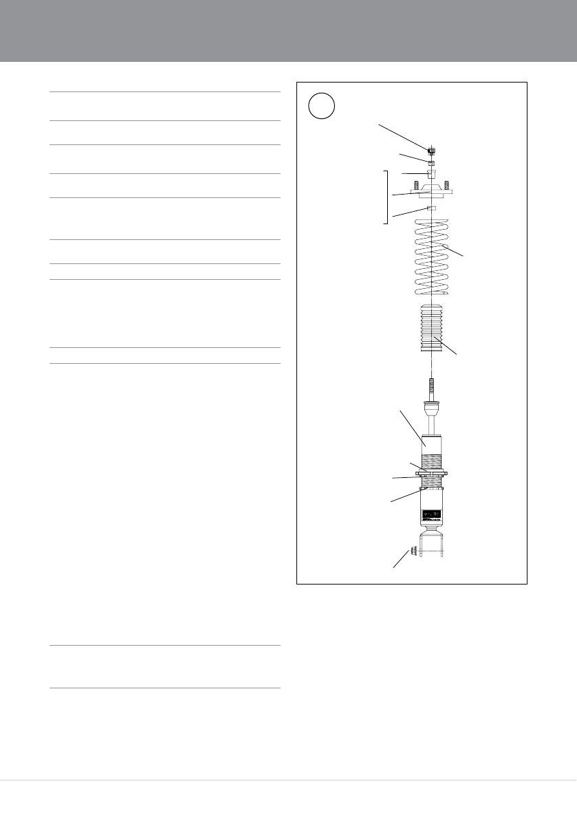
1
/RFNQXW
6SULQJ
%HDULQJVSDFHU
/RFNQXW0
7RSPRXQW
'XVWERRW
6KRFN
DEVRUEHU
/RFNQXW
%HDULQJVSDFHU
$GMXVWPHQW
NQRE
Lower
spring seat
㻸㼛㼏㼗㻌㼚㼡㼠㻌㻹㻝㻠

7
Note!1
Make sure that all bolts are tightened to the
correct torque and that nothing fouls or restricts
movement of the shock absorber when it is
being fully compressed or extended.
8
Make sure that all removed parts are
reinstalled in the same way as they were
before the installation of the Öhlins shock
absorber.
MOUNTING INSTRUCTIONS
2
Cu
t
Öhlins Racing AB
Box 722
S-194 27 Upplands Väsby, Sweden
Phone +46 8 590 025 00
fax +46 8 590 025 80
© Öhlins Racing AB. All rights
reserved. Any reprinting or
unauthorized use without the written
permission of Öhlins Racing AB
is prohibited.
Öhlins products are subject to
continuous improvement and
development, therefore, although
these instructions include the most
up-to-date information available at
the time of printing, minor updates
may occur.
To nd the latest information
contact an Öhlins distributor.
Please contact Öhlins if you have
any questions regarding the
contents in this document.
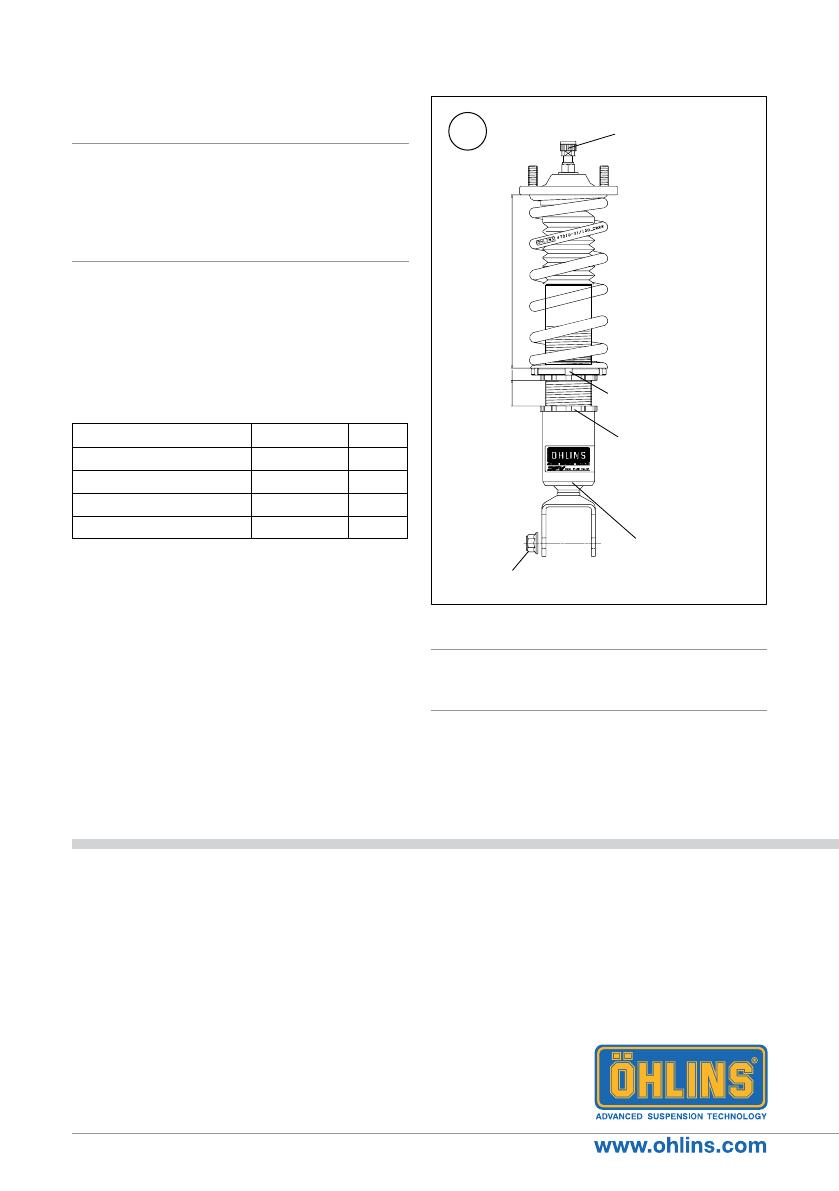
㻾㼑㼎㼛㼡㼚㼐
㼍㼐㼖㼡㼟㼠㼑㼞
㻿㼜㼞㼕㼚㼓㻌㼜㼞㼑㼘㼛㼍㼐
㼍㼐㼖㼡㼟㼠㼑㼞
㻴㼑㼕㼓㼔㼠
㻌㼍㼐㼖㼡㼟㼠㼑㼞
㻮㼞㼍㼏㼗㼑㼠
㻺㼥㼘㼛㼚㻌㼚㼡㼠㻌㻹㻝㻠
3
SETUP DATA
Warning!⚠
Before you ride/drive, always make sure that the
setup is according to the recommended setup
data. Read about adjustments and setting up
in the Öhlins Owner’s Manual before you make
any adjustments. Contact an Öhlins dealer if you
have any questions about setting up.
The standard preload is 9 mm from a free
length of 200 mm, giving 191 mm installed
length, see g 3.
Part no. MI_HOSMI20_3
Issued 2017-06-13
Rebound setting
Track 5-10 clicks
Winding road 10-15 clicks
Street 15-20 clicks
Spring preload 9 mm
Recommended spring
Spec H200, ID65, 80 N/mm
The actual vehicle height
With both the preload and height adjustments
in their standard positions, the vehicle is
lowered approximately 25 mm when compared
to the original suspension. As the height
adjuster is turned one rotation, the position
moves 1.5 mm.
Warning!⚠
The adjustment range is the standard
position±15 mm. If the bracket is moved outside
the adjustment range, it may come loose.
ADJUSTMENTS
/