Century RADS-101Q Installation, Operation & Maintenance Manual
- Category
- Mobile air conditioners
- Type
- Installation, Operation & Maintenance Manual

www.marsdelivers.com
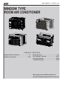
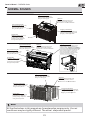
Owner’s Manual
RG/RADS Series
Window Type Room Air Conditioner
RG-51Q
RADS-51Q
RADS-61Q
RADS-81Q
RADS-101Q
RADS-121Q
RADS-151Q

Owner’s Manual - RG/RADS Series
Before using your air conditioner, please read
this manual carefully and keep it for future reference.
WINDOW TYPE
ROOM AIR CONDITIONER
Before using your air conditioner, please read
this manual carefully and keep it for future reference.
WINDOW TYPE
ROOM AIR CONDITIONER
Before using your air conditioner, please read
this manual carefully and keep it for future reference.
WINDOW TYPE
ROOM AIR CONDITIONER
Before using your air conditioner, please read
this manual carefully and keep it for future reference.
WINDOW TYPE
ROOM AIR CONDITIONER
Before using your air conditioner, please read
this manual carefully and keep it for future reference.
WINDOW TYPE
ROOM AIR CONDITIONER
Before using your air conditioner, please read
this manual carefully and keep it for future reference.
WINDOW TYPE
ROOM AIR CONDITIONER
Before using your air conditioner, please read
this manual carefully and keep it for future reference.
WINDOW TYPE
ROOM AIR CONDITIONER
Before using your air conditioner, please read
this manual carefully and keep it for future reference.
WINDOW TYPE
ROOM AIR CONDITIONER
Before using your air conditioner, please read
this manual carefully and keep it for future reference.
WINDOW TYPE
ROOM AIR CONDITIONER
Before using your air conditioner, please read
this manual carefully and keep it for future reference.
WINDOW TYPE
ROOM AIR CONDITIONER
Before using your air conditioner, please read
this manual carefully and keep it for future reference.
WINDOW TYPE
ROOM AIR CONDITIONER
Before using your air conditioner, please read
this manual carefully and keep it for future reference.
WINDOW TYPE
ROOM AIR CONDITIONER
Before using your air conditioner, please read
this manual carefully and keep it for future reference.
WINDOW TYPE
ROOM AIR CONDITIONER
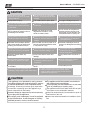
TABLE OF CONTENTS
Installation Instructions
...............................................23
10-22
Normal Sounds
.................................
......................................
Important Safety Instructions ..........................1-9
Troubleshooting Tip 29-30
.....................................
Air Conditioner Features 24-28
.............................
Care and Cleaning 28-29
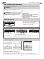
Sleep
Check
Filter
Follow
Me
Auto
On/off
Fan
High
Med
Low
Energy
Saver
on
off
Timer
Auto
Fan
Cool
Dry
Mode
TEMP
/TIMER
TEMP/TIMER
Heat

Owner’s Manual - RG/RADS Series
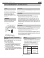
IMPORTANT SAFETY INSTRUCTIONS
Inside you will find many helpful hints on how to use and maintain your air conditioner
properly. Just a little preventive care on your part can save you a great deal of time
and money over the life of your air conditioner. You'll find many answers to common
problems in the chart of troubleshooting tips. If you review our chart of Troubleshooting
Tips first, you may not need to call for service at all.
To prevent injury to the user or other people and property damage, the following
instructions must be followed. Incorrect operation due to ignoring of instructions may
cause harm or damage. The seriousness is classified by the following indications.
This symbol indicates the possibility of death or serious injury.
Always do this.
Never do this.
CAUTION
This symbol indicates the possibility of injury or damage to property.
WARNING
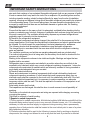
WARNING
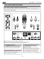
Plug in power plug
properly.
Do not modify power cord length or share the
outlet with other appliances.
Always ensure effective
grounding.
Unplug the unit if strange
sounds, smell, or smoke
comes from it.
Keep firearms away.
Ventilate room before operating air conditioner if there is
a gas leakage from another appliance.
Otherwise, it may cause electric
shock or fire due to excess heat
generation.
It may cause electric shock or fire due to heat generation.
Incorrect grounding may cause
electric shock.
It may cause fire and electric
shock.
It may cause fire.
It may cause explosion, fire and, burns.
It may cause electric shock or fire
due to heat generation.
It may cause electric shock.
It may cause failure of machine
or electric shock.
It may cause fire and electric
shock.
It may cause fire and electric
shock.
It may cause electric shock or fire.
If the power cord is damaged, it must be replaced by
the manufacturer or an authori••ed service cent• ••• or a
similarly qualified person in order to avoid a hazard.
This could damage your health.
Incorrect installation may cause
fire and electric shock.
It may cause electric shock.
It may cause an explosion or fire.
It may cause failure and electric shock.
Do not operate or stop the
unit by inserting or pulling
out the power plug.
Do not operate with wet
hands or in damp
environment.
Do not allow water to run
into electric parts.
Do not use the socket if it is
loose or damaged.
Do not use the power cord
close to heating appliances.
Do not damage or use an unspecified power
cord.
Do not direct airflow at room occupants.
Always install • •••circuit
breaker and a dedicated••
power circuit.
Do not open the unit during operation.
Do not use the power cord near flammable gas
or combustibles, such as gasoline, benzene,
thinner, etc.
Do not disassemble or modify unit.
!
!
!
!
!
!
!
!
READ THIS MANUAL
1
manufacturer or an authorized service center or a similarly
qualied person in order to avoid hazard.
Always install a circuit
breaker and a dedicated
power circuit.

Owner’s Manual - RG/RADS Series
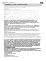
When the air filter is to be
removed, do not touch the metal
parts of the unit.
It may cause an injury.
Do not clean unit when power is on
as it may c ause fi re an d el ectric sh ock,
it may cause an injury.
Operation with windows opened
may cause wetting of indoor and
soaking of household furniture.
When the unit is to be cleaned,
switch off, and turn off the circuit
breaker.
Use caution when unpacking and
installing. Sharp edges could cause injury.
Do not clean the air conditioner
with water.
Water may enter the unit and
degrade the insulation. It may
cause an electric shock.
This could injure the pet or plant.
It may cause electric shock and
damage.
Do not put a pet or house plant
where it will be exposed to direct
air flow.
Ventilate the room well when
used together with a stove, etc.
An oxygen shortage may occur.
Do not use this air conditioner to
preserve precision devices, food,
pets, plants, and art objects.It may
cause deterioration of quality, etc.
It may cause failure of product or
fire.
Do not use for special purposes.
If water enters the unit, turn the unit off at the power
outlet and switch off the circuit breaker. Isolate
supply by taking the power-plug out and contact a
qualified service technician.
!
!
!
!
It may cause failure of appliance
or accident.
Appearance may be deteriorated
due to change of product color or
scratching of its surface.
If bracket is damaged, there is
concern of damage due to falling
of unit.
There is danger of fire or electric
shock.
Operation without filters may••
cause failure.
It contains contaminants and
could make you sick.
Stop operation and close the
window in storm or hurricane.
!
Do not use strong detergent
such as wax or thinner but use
a soft cloth.
Ensure that the installation bracket of the
outdoor appliance is not damaged due
to prolonged exposure.
Hold the plug by the head of the
power plug when taking it out.
!
Turn off the main power
switch when not using the
unit for a long time.
!
!
!
Always insert the filters securely.
Clean filter once every t wo w eeks.
!
Do not place heavy object on the power
cord and ensure that the cord is not
compressed.
Do not drink water drained
from air conditioner.
This appliance is not intended for use by persons
(including children) with reduced physical ,sensory
or mental capabilities or lack of experience and
knowledge, unless••they••• • • • •• • • • •••••••••••given••supervision••
or instruction concerning use of the appliance by a
person responsible for their safety.
Children should be supervised to ensure that they
do not play with the appliance.
If the supply cord is damaged, it must be replaced
by the manufacturer, its service agent or similarly
qualified persons in order to avoid a hazard.
CAUTION
2
CAUTION
Do not place obstacles around
air-inlets or inside of air-outlet.
The appliance shall be installed in accordance
with national wiring regulations.
Do not operate your air conditioner in a wet room
such as a bathroom or laundry room.
The appliance with electric heater shall have at
least •• •• • •••••••s pace••to the••••co mbustible••materials.••
Contact••the authori••ed service technician for••
repair or maintenance of this unit.
Contact the authori••ed installer for installation••of
this unit.
IMPORTANT SAFETY INSTRUCTIONS
knowledge, unless they have been given supervision
or instruction concerning use of the appliance by a
person responsible for their safety.
The appliance with electric heater shall have at least
3 feet space to the combustible materials.
Contact an authorized service technician for repair or
maintenance of this unit.
Contact the authorized installer for installation of this
unit.

Owner’s Manual - RG/RADS Series
The power supply cord with this air
conditioner contains a current detection
device designed to reduce the risk of
re. Please refer to the section Operation
of Current Device for details. In the
event that the power supply cord is
damaged, it cannot be repaired- it must
be replaced with a cord from the Product
Manufacturer.
Prevent Accidents
To reduce the risk of re, electrical shock, or injury to persons when using your air
conditioner, follow basic precautions, including the following:
• Be sure the electrical service is adequate for the model you have chosen. This
information can be found on the serial plate, which is located on the side of the
cabinet and behind the grille.
• If the air conditioner is to be installed in a window, you will probably want to clean
both sides of the glass rst. If the window is a triple-track type with a screen panel
included, remove the screen completely before installation.
• Be sure the air conditioner has been securely and correctly installed according to the
installation instructions in this manual. Save this manual for possible future use when
removing or installing this unit.
• When handling the air conditioner, be careful to avoid cuts from sharp metal ns on
front and rear coils.
IMPORTANT SAFETY INSTRUCTIONS
WARNING
WARNING
WARNING
NOTE
NOTE
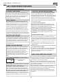
Operation of Current Device
(Applicable to the unit with current detection
device only)
WARNING
For Your Safety
Do not store or use gasoline or other ammable vapors and liquids in the vicinity
of this or any other appliance.
Avoid re hazard or electric shock. Do not use
an extension cord or an adapter plug. Do not
remove any prong from the power cord.
Grounding type wall
receptacle
Electrical Information
The complete electrical rating of your new room air conditioner is stated on the serial plate.
Refer to the rating when checking the electrical requirements.
• Be sure the air conditioner is properly grounded. To minimize shock and re hazards,
proper grounding is important. The power cord is equipped with a three-prong
grounding plug for protection against shock hazards.
• Your air conditioner must be used in a properly grounded wall receptacle. If the wall
receptacle you intend to use is not adequately grounded or protected by a time delay
fuse or circuit breaker, have a qualied electrician install the proper receptacle. Ensure
the receptacle is accessible after the unit installation.
• Do not run air conditioner without the side protective cover in place. This could result
in mechanical damage within the air conditioner.
• Do not use an extension cord or an adapter plug.
The power supply cord contains a current device that
senses damage to the power cord. To test your power
supply cord do the following:
1. Plug in the air conditioner.
2. The power supply cord will have TWO buttons on
the plug head. Press the TEST button, you will
notice a click as the RESET button pops out.
3. Press the RESET button, again you will notice a
click as the button engages.
4. The power supply cord is not supplying electricity
to the unit. (On some products this it also indicated
by a light on the plug head.)
3
• Do not use this device to turn the unit on or off.
• Always make sure the RESET button is pushed in for current
operation.
• The power supply must be replaced if it fails reset when either
the TEST button is pushed, of it cannot be reset. A new one
can be obtained from the product manufacturer.
• If power supply cord is damaged, it cannot be repaired.
It MUST be replaced by one obtained from the product
manufacturer.
NOTE: This air conditioner is designed to be operated under
conditions as follows:
Cooling
Operation
Outdoor temp:
64-109°F/18-43°C
(64-125°F/18-52°C for special
tropical models)
Indoor temp:
62-90°F/17-32°C
Heating
Operation
Outdoor temp:
23-76°F/-5-24°C
Indoor temp:
32-80°F/0-27°C
Note: Performance may be reduced outside of these
operating temperatures.

Owner’s Manual - RG/RADS Series
4
IMPORTANT SAFETY INSTRUCTIONS
-Do not use means to ac celerate the defrosting pr ocess or to cl ean, other th an those••
recommended by the m anufacturer.
-The appliance sh all be st ored in a ro om without continuously op erating ignition
sources (for ex ample: open flames, an op erating gas appliance) an d i gnition so urces••or
(for example:an op erating electric he ater) close to the ap pliance.
-Do not pierce or burn.
-Be aware th at the refrigerants may no t c o ntain an od or.
-Compliance with n a tional gas r egulations sh all be ob served.
-Keep ventilation op enings clear of obstruction.
-The appliance sh all be st ored so as to p revent mechanical da mage from oc curring.
-••he ap pliance shall be stored in a well-ventilated area where th e r oom
size corresponds to the room ar ea as s p ecified fo r o peration.
-Any person who is involved with working on or br eaking into a re frigerant circuit sh ould
hold a current va lid certificate fr om an in dustry-accredited assessment au thority, which••
authori••es their co mpetence to ha ndle refrigerants sa fely in ac cordance with an
industry recogni••ed as sessment specification.
-Servicing shall on ly b e pe rformed as re commended by the equipment manufacturer.••
Maintenance and r e pair requiring th e a ssistance of ot her skilled pe rsonnel shall b e
carried out u n der the supervision of the pe rson c o mpetent in t h e use of flammable re
frigerants.
-DO NOT m odify th e l ength of the po wer co rd or use an ex tension cord to power th e u n it.
DO NOT s h are a single o u tlet with other el ectrical appliances. I mproper po wer supply
can cause fire or electrical shock.
-Please follow th e i nstruction ca refully to ha ndle, install, cl ear, se rvice th e a i r
conditioner to avoid any damage or hazard. Flammable Refrigerant R32 is used within
air conditioner. When maintaining or di sposing the air co nditioner, th e r e frigerant (R32
or R290) shall be recovered pr operly, sh all not discharge to air directly.
-No open fire or device which may generate sp ark/arcing shall be
around air c o nditioner to avoid causing ig nition of th e flammable re frigerant used.
Please follow th e i nstruction•• ca refully to s tore or maintain the air conditioner to prevent••
mechanical damage fr om oc curring.
-Flammable r e frigerant -R32 is used in •• •• ••••••air c onditioner. Please fo llow the instruction••
carefully to av oid any hazard.
WARNING: (for using R290/R32 refrigerant only)
Caution: Risk of fire/
flammable materials
(Required for R32/R290 units only)
IMPORTANT NOTE:Read this manual
carefully before installing or operating
your new air conditioning unit. Make sure
to save this manual for future reference.
AVERTISSEMENT
Ne pas utiliser de produits permettant d acc l rer le d gel ou de produits de nettoyage
autres que ceux recommand s par le fabricant.
L appareil doit tre entrepos dans un endroit sans source d allumage fonctionnant
en continu (par exemple : flamme nue, appareil au gaz en marche ou radiateur lectrique
en marche).
Ne pas percer ni bruler.
Attention : les frigorig nes peuvent tre inodores.
,
,
,
• Do not use means to accelerate the defrosting process or to clean, other than those reccommended
by the manufacturer.
• The appliance shall be stored in a room without continuously operating ignition sources (for example:
open ames, an operating gas appliance) and ignition source or (for example: an operating electric
heater) close to the appliance.
• Do not pierce or burn.
• Be aware that the refrigerants may not contain an odor.
• Compliance with national gas regulations shall be observed.
• Keep ventilation openings clear of obstruction.
• The appliance shall be stored so as to prevent mechanical damage from occurring. The appliance
shall be stored in a well-ventilated area where the room size corresponds to the room area as
specied for operation.
• Any person who is involved with working on or breaking into a refrigerant circuit should hold a current
valid certicate from an industry-accredited assessment authority, which authorizes their competence
to handle refrigerants safely in accordance with an industry recognized assessment specication.
• Servicing shall only be performed as recommended by the equipment manufacturer. Maintenence and
repair requiring the assistance of other skilled personnel shall be carried out under the supervision of
the person competent in the use of ammable refrigerants.
• DO NOT modify the length of the power cord or use an extension cord to power the unit. DO NOT
share a single outlet with other electrical appliances. Improper power supply can cause re or
electrical shock.
• Please follow the instruction carefully to handle, install, clear, service the air conditioner to avoid any
damage or hazard. Flammable Refrigerant R32 is used within air conditioner. When maintaining or
disposing the air conditioner, the refrigerant (R32 or R290) shall be recovered properly, shall not
discharge to air directly. No open re or device which may generate spark/arcing shall be around air
conditioner to avoid causing ignition of the ammable refrigerant used. Please follow the instructions
carefully to store or maintain the air conditioner to prevent mechanical damage from occurring.
• Flammable refrigerant -R32 is used in this air conditioner. Please follow the instructions carefully to
avoid any hazard.

Owner’s Manual - RG/RADS Series
Explanation of symbols displayed on the unit (R32/R290 Refrigerant only):
1) Checks to the area
Prior to beginning work on systems containing ammable refrigerants, safety checks are necessary to
ensure that the risk of ignition is minimized. For repair to the refrigerating system, the following precau-
tions shall be complied with prior to conducting work on the system.
2) Work procedure
Work shall be undertaken under a controlled procedure so as to minimize the risk of a ammable gas or
vapor being present while the work is being performed.
3) General work area
All maintenence staff and others working in the local area shall be instructed on the nature of work
being carried out. Work in conned spaces shall be avoided. The area around the workspace shall be
sectioned off. Ensure that the conditions within the area have been made safe by control of ammable
material.
4) Checking for presence of refrigerant
The area shall be checked with an appropriate refrigerant detector prior to and during work, to ensure
the technician is aware of potentially ammable atmospheres. Ensure that the leak detection equipment
being used is suitable for use with ammable refrigerants, i.e. non-sparking, adequately sealed or
intrinsically safe.
5)Presence of re extinguisher
If any hot work is to be conducted on the refrigeration equipment or any associated parts, appropriate re
extinguishing equipment shall be available at hand. Have a dry powder or CO2 re extinguisher adjacent
to the charging area.
6) No ignition sources
No person carrying out work to a refrigeration system which involves exposing any
IMPORTANT SAFETY INSTRUCTIONS
5
WARNINGS (for using R290/R32 refrigerant only)
1. Transport of equipment containing ammable refrigerants
See transport regulations
2. Marking of equipment using signs
See local regulations
3. Disposal of equipment using ammable refrigerants
See national regulations.
4. Storage of equipment/appliances
The storage of equipment should be in accordinance with the manufacturer’s instructions.
5. Storage of packed (unsold) equipment
Storage package protection should be constructed such that mechanical damage to the equipment
inside the package will not cause a leak of the refrigerant charge.
The maximum number of pieces of equipment permitted to be stored together will be determined by
local regulations.
6. Information on servicing
This symbol shows that this appliance uses a ammable refrigerant. If the refrigerant is
leaked and exposed to an external ignition source, there is a risk of re.
This symbol shows that the operation manual should be read carefully.
This symbol shows that service personnel should handle this equipment with reference to
the installation manual.
This symbol shows that information is available such as the operating manual or
installation manual.

Owner’s Manual - RG/RADS Series
6
IMPORTANT SAFETY INSTRUCTIONS
pipe work that contains or has contained flammable refrigerant shall use any sources of ignition
in such a manner that it may lead to the risk of fire or explosion. All possible ignition sources,
including cigarette smoking, should be kept sufficiently far away from the site of installation,
repairing, removing and disposal, during which flammable refrigerant can possibly be released
to the surrounding space. Prior to work taking place, the area around the equipment is to be
surveyed to make sure that there are no flammable hazards or ignition risks. No Smoking
signs shall be displayed.
7)Ventilated area
Ensure that the area is in the open or that it is adequately ventilated before breaking into the
system or conducting any hot work. A degree of ventilation shall continue during the period that
the work is carried out. The ventilation should safely disperse any released refrigerant and
preferably expel it externally into the atmosphere.
8)Checks to the refrigeration equipment
Where electrical components are being changed, they shall be fit for the purpose and to the
correct specification. At all times the manufacturer's maintenance and service guidelines shall
be followed. If in doubt consult the manufacturer's technical department for assistance.
The following checks shall be applied to installations using flammable refrigerants:
The charge size is in accordance with the room size within which the refrigerant containing
parts are installed;
The ventilation machinery and outlets are operating adequately and are not obstructed;
If an indirect refrigerating circuit is being used, the secondary circuit shall be checked for the
presence of refrigerant;
Marking to the equipment continues to be visible and legible. Markings and signs that are
illegible shall be corrected;
Refrigeration pipe or components are installed in a position where they are unlikely to be
exposed to any substance which may corrode refrigerant containing components, unless the
components are constructed of materials which are inherently resistant to being corroded or
are suitably protected against being so corroded.
9)Checks to electrical devices
Repair and maintenance to electrical components shall include initial safety checks and
component inspection procedures. If a fault exists that could compromise safety, then no
electrical supply shall be connected to the circuit until it is satisfactorily dealt with. If the fault
cannot be corrected immediately but it is necessary to continue operation, an adequate
temporary solution shall be used. This shall be reported to the owner of the equipment so all
parties are advised.
Initial safety checks shall include:
That capacitors are discharged: this shall be done in a safe manner to avoid possibility of
sparking;
That there no live electrical components and wiring are exposed while charging, recovering
or purging the system;
That there is continuity of earth bonding.
7.Repairs to sealed components
• •••During repairs to sealed components, all electrical supplies shall be disconnected from the••
equipment being worked upon prior to any removal of sealed covers, etc. If it is••absolutely••
necessary to have an electrical supply to equipment during servicing, then a permanently••
operating form of leak detection shall be located at the most critical point to warn of a••
potentially hazardous situation.
• •••Particular attention shall be paid to the following to ensure that by working on electrical••
components, the casing is not altered in such a way that the level of protection is affected.
1) During repairs to sealed components, all electrical supplies shall be disconnected from the
equipment being worked upon to prior to any removal of sealed covers, etc. If it is absolutely
necessary to have an electrical supply to equipment during servicing, then a permanently
operating form of leak protection shall be located at the most critical point to warn of a poten-
tially hazardous situation.
2) Particular attention shall be paid to the following to ensure that by working on electrical
components, the casing is not altered in such a way that the level of protection is affected.

Owner’s Manual - RG/RADS Series
7
IMPORTANT SAFETY INSTRUCTIONS
This shall include damage to cables, excessive number of connections, terminals not made
to original specification, damage to seals, incorrect fitting
of glands, etc.
Ensure that apparatus is mounted securely.
Ensure that seals or sealing materials have not degraded such that they no longer serve the
purpose of
preventing the ingress of flammable atmospheres. Replacement parts shall be in accordance
with the manufacturer's specifications.
NOTE: The use of silicon sealant may inhibit the effectiveness of some types of leak detection
equipment. Intrinsically safe components do not have to be isolated prior to working on them.
8.Repair to intrinsically safe components
Do not apply any permanent inductive or capacitance loads to the circuit without ensuring that
this will not exceed the permissible voltage and current permitted for the equipment in use.
Intrinsically safe components are the only types that can be worked on while live in the
presence of a flammable atmosphere. The test apparatus shall be at the correct rating.
Replace components only with parts specified by the manufacturer. Other parts may result in
the ignition of refrigerant in the atmosphere from a leak.
9.Cabling
Check that cabling will not be subject to wear, corrosion, excessive pressure, vibration, sharp
edges or any other adverse environmental effects. The check shall also take into account the
effects of aging or continual vibration from sources such as compressors or fans.
10.Detection of flammable refrigerants
Under no circumstances shall potential sources of ignition be used in the searching for or
detection of refrigerant leaks. A halide torch (or any other detector using a naked flame) shall
not be used.
11.Leak detection methods
The following leak detection methods are deemed acceptable for systems containing flammable
refrigerants. Electronic leak detectors shall be used to detect flammable refrigerants, but the
sensitivity may not be adequate, or may need re-calibration. (Detection equipment shall be
calibrated in a refrigerant-free area.) Ensure that the detector is not a potential source of ignition
and is suitable for the refrigerant used. Leak detection equipment shall be set at a percentage of
the LFL of the refrigerant and shall be calibrated to the refrigerant employed and the appropriate
percentage of gas (25 % maximum) is confirmed. Leak detection fluids are suitable for use with
most refrigerants but the use of detergents containing chlorine shall be avoided as the chlorine
may react with the refrigerant and corrode the copper pipe-work. If a leak is suspected, all
naked flames shall be removed/ extinguished. If a leakage of refrigerant is found which requires
brazing, all of the refrigerant shall be recovered from the system, or isolated (by means of shut
off valves) in a part of the system remote from the leak. Oxygen free nitrogen (OFN) shall then
be purged through the system both before and during the brazing process.
12.Removal and evacuation
When breaking into the refrigerant circuit to make repairs or for any other purpose conventional
procedures shall be used. However, it is important that best practice is followed since
flammability is a consideration. Opening of the refrigeration systems shall not be done by brazing.
The following procedure shall be adhered to:
Remove refrigerant;
Purge the circuit with inert gas;
Evacuate;
Purge again with inert gas;
Open the circuit by cutting or brazing.
,

Owner’s Manual - RG/RADS Series
13. Charging procedures
In addition to conventional charging procedures, the following requirements shall be followed.
Ensure that contamination of different refrigerants does not occur when using charging
equipment. Hoses or lines shall be as short as possible to minimize the amount of refrigerant
contained in them.
Cylinders shall be kept upright.
Ensure that the refrigeration system is grounded prior to charging the system with refrigerant.
Label the sustem when charging is complete (if not already).
Extreme care shall be taken not to overll the refrigeration system.
Prior to recharging the system it shall be pressure tested with OFN. The system shall be
leak tested on completion of charging but prior to comissioning. A follow up leak test shall be
carried out prior to leaving the site.
14. Decomissioning
Before carrying out this procedure, it is essential that the technician is completely familiar
with the equipment and all its detail. It is reccommended good practice that all refrigerants
are recovered safely. Prior to the task being carried out, an oil and refrigerant sample shall be
taken in case analysis is required prior to re-use of reclaimed refrigerant. It is essential that
electrical power is available before the task is commenced.
IMPORTANT SAFETY INSTRUCTIONS
The refrigerant charge shall be recovered into the correct recovery cylinders. The system shall
be ushed with OFN to render the unit safe. This process may need to be repeated several
times. Compressed air or oxygen shall not be used for this task.
Flushing shall be achieved by breaking the vacuum in the system with OFN and continuing to
ll until the working pressure is achieved, then venting to atmosphere, and nally pulling down
to a vacuum. This process shall be repeated until no refrigerant is within the system. When the
nal OFN charge is used, the system shall be vented down to atmospheric pressure to enable
work to take place. This operation is absolutely vital if brazing operations on the pipe-work are
to take place.
Ensure that the outlet for the vacuum pump is not close to any ignition sources and there is
ventilation available.
a) Become familiar with the equipment and its operation.
b) Isolate system electrically
c) Before attempting the procedure, ensure that:
Mechanical handling equipment is available, if required, for handling refrigerant cylinders; All
personal protective equipment is available and being used correctly;
The recovery process is supervised at all times by a competent person;
Recovery equipment and cylinders conform to the appropriate standards.
d) Pump down refrigerant system, if possible.
e) If a vacuum is not possible, make a manifold so that refrigerant can be removed from
various parts of the system.
f) Make sure that cylinder is situated on the scales before recovery takes place.
g) Start the recovery machine and operate in accordance with manufacturer’s instructions.
h) Do not overll cylinders. (No more than 80% volume liquid charge).
i) Do not exceed the maximum working pressure of the cylinder, even temporarily.
j) When the cylinders have been lled correctly and the process completed, make sure that the
cylinders and
8

Owner’s Manual - RG/RADS Series
9
IMPORTANT SAFETY INSTRUCTIONS
the equipment are removed from site promptly and all isolation valves on the equipment are
closed off.
k) Recovered refrigerant shall not be charged into another refrigeration system unless it has
been cleaned and checked.
15.Labelling
Equipment shall be labelled stating that it has been de-commissioned and emptied of
refrigerant. The label shall be dated and signed. Ensure that there are labels on the equipment
stating the equipment contains flammable refrigerant.
16.Recovery
When removing refrigerant from a system, either for servicing or decommissioning, it is
recommended good practice that all refrigerants are removed safely.
When transferring refrigerant into cylinders, ensure that only appropriate refrigerant recovery
cylinders are employed. Ensure that the correct number of cylinders for holding the total system
charge is available. All cylinders to be used are designated for the recovered refrigerant and
labelled for that refrigerant (i.e. special cylinders for the recovery of refrigerant). Cylinders shall
be complete with pressure relief valve and associated shut-off valves in good working order.
Empty recovery cylinders are evacuated and, if possible, cooled before recovery occurs.
The recovery equipment shall be in good working order with a set of instructions concerning
the equipment that is at hand and shall be suitable for the recovery of flammable refrigerants.
In addition, a set of calibrated weighing scales shall be available and in good working order.
Hoses shall be complete with leak-free disconnect couplings and in good condition. Before
using the recovery machine, check that it is in satisfactory working order, has been properly
maintained and that any associated electrical components are sealed to prevent ignition in the
event of a refrigerant release. Consult manufacturer if in doubt.
The recovered refrigerant shall be returned to the refrigerant supplier in the correct recovery
cylinder, and the relevant Waste Transfer Note arranged. Do not mix refrigerants in recovery
units and especially not in cylinders. If compressors or compressor oils are to be removed,
ensure that they have been evacuated to an acceptable level to make certain that flammable
refrigerant does not remain within the lubricant. The evacuation process shall be carried out
prior to returning the compressor to the suppliers. Only electric heating to the compressor
body shall be employed to accelerate this process. When oil is drained from a system, it shall
be carried out safely.

Owner’s Manual - RG/RADS Series
10
INSTALLATION INSTRUCTIONS(for 5000 to 12000Btu/h)
Read these instructions completely
and carefully.
IMPORTANT- Save these••instructions
for local inspector••s use.
IMPORTANT- Observe all••governing
codes and ordi••ances.
Note to Installer- Be sure to leave these••
instructions with the Consumer.
Note to Consumer- Keep these••
instructions for fut• •••e reference.
Skill level- Installatio•• of this appliance••
requires basic mechanical skills.
Completion time- Approximately 1 hour.••
We recommend that two people install••this
product.
Proper installation is the responsibility
of the installer.
Product failure due to improper installation••is
not covered under the Warranty.
You MUST use all supplied parts and use••
proper installation procedures as described••in
these instructions when installing this air••
conditioner.
BEFORE YOU BEGIN
CAUTION
Do not, under any circumstances, cut or••
remove the third (ground) prong from the••
power cord.
Do not change the plug on the power cord••
of the air conditioner.
Aluminum house wiring may present special••
problems- consult a qualified electr••cian.
When handling unit, be careful to avoid cuts from••
sharp metal edges and aluminum fins on front and••
rear coils.
TOOLS YOU WILL NEED
Screwdriver
Level
TOOLS YOU MAY USE
Screwdriver
Pencil
Ruler or tape measure
Scissors or knife
Save Carton and these Installation Instructions
for future reference. The carton is the best way
to store unit during winter, or when not in use.
NOTE:
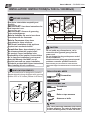
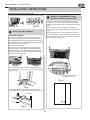
WINDOW REQUIREMENTS
H
Your air conditioner is designed to install in
standard double hung windows with opening
widths of 23 to 36 inches(584mm to 914mm) .
Model
H
6000~8000Btu/h
10000~12000Btu/h
14 (356mm)
15-1/2 (394mm)
Table 1
5000~6000Btu/h
13 (330mm)
H
Read these instructions completely and
carefully.
IMPORTANT- Save these instructions for
local inspector’s use.
IMPORTANT- Observe all governing
codes and ordinances.
Note to Installer- Be sure to leave these
instructions with the Consumer.
Note to Consumer- Keep these
instructions for future reference.
Skill level- Installation of this appliance
requires basic mechanical skills.
Completion time- Approximately 1 hour.
We recommend that two people install
this product. Proper installation is the
responsibility of the installer. Product failure
due to improper installation is not covered
under the Warranty. You MUST use all
supplied parts and use proper installation
procedures as described in these instructions
when installing this air conditioner.
Do not, under any circumstances, cut or
remove the third (ground) prong from the
power cord.
Do not change the plug on the power cord of
the air conditioner.
Aluminum house wiring may present special
problems- consult a qualied electrician.
When handling unit, be careful to avoid cuts from
sharp metal edges and aluminum ns on front and rear
coils.

Owner’s Manual - RG/RADS Series
11
INSTALLATION INSTRUCTIONS
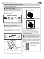
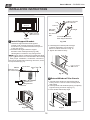
PREPARE THE WINDOW
1
1/ Screws
(7)
2
Lock Frame
(2)
Sash Lock
(1)
Mounting Hardware
Window sash
seal foam
(1)
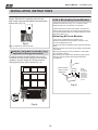
PREPARE AIR CONDITIONER
2
Lower sash must open sufficiently to allow a clear
vertical opening of 13 inches (330mm). Side louvers
and the rear of the AC must have clear air space to
allow enough airflow through the condenser, for heat
removal. The rear of the unit must be outdoors, not
inside a building or garage.
A: Remove the air conditioner from the carton and
place on a flat surface.
B: Remove top rail and R1 hardware (R1 hardware
only for Energy star models) from the packaging
material as shown in Fig. A.
Top Rail Hardware
3/8 Screws
(4)
Top Rail
(1)
Packaging
Fig.A
Top Rail
R1 hardware
(2)
R1 hardware(for
>
)
10000Btu/h models
only
R1 hardware
(for <
)
10000
Btu/h models
only
Fig.C
NOTE: The top rail hardware and the Fig.A,
Fig.B and Fig.C are not applicable to the units
more than 10000Btu/h. Before installing unit,
the top rail must be assembled on the unit (For
<10000Btu/h models only).
C: Align the hole in the top rail with those in the top
of the unit as shown in Fig.B
D: Secure the top rail to the unit with the 3/8 Screws
as shown in Fig.C.
NOTE: For safety reasons, all four(4) screws MUST
be securely fastened.
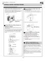
INSTALL THE ACCORDION PANELS
3
NOTE: Top rail and Sliding Panels at each side are
offset to provide the proper pitch to the rear of (5/16 ).
This is
necessary for proper condensed water
utilization and drainage. If you are not using the Side
Panels for any reason, this pitch to the rear must be
maintained.
A.Place unit on floor, a bench or
a table. Hold the Accordion
Panel in one hand and gently
pull back the center to free the
open end. See Fig.1
Fig.1
Fig.B
Lock Frame
(2)
(For Wooden
windows)
(For Vinyl-Clad
windows)

Owner’s Manual - RG/RADS Series
12
INSTALLATION INSTRUCTIONS
SECURE THE ACCORDION PANELS
4
B. Slide the free end " " section of the panel directly
into the cabinet as shown in Fig. 2. Slide the panel
down. Be sure to leave enough space to slip the
top and bottom of the frame into the rails on the
cabinet.
Fig.2
" "section
C. Once the panel has been installed on the side of
the cabinet, make sure it sits securely inside the
frame channel by making slight adjustments.
Slide the top and bottom ends of the frame into the
top and bottom rails of the cabinet. Fig.3.
D. Slide the panel all the way in and repeat on the
other side.
Top Rail
Bottom Rail
Fig.3
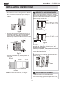
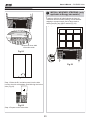
A.Keep a firm grip on the air conditioner, carefully
place the unit into the window opening so the bottom
of the air conditioner frame is against the window
sill (Fig.5A and Fig.5B). Carefully close the window
behind the top rail of the unit.
Fig.5A
NOTE: If storm window blocks AC, see Fig. 11.
Top Rail
Bottom Rail
Top left
Top right
Fig.4
Wooden Windows
INSIDE
OUTSIDE
H:About 3/4 to 1 for 5 to 8K);
Measure from the cabinet edge
3
H:About 1 to 1 / for 10 to12K);
8
H
Fig.5B
Vinyl-Clad Windows
INSIDE
OUTSIDE
H:About 3/4 to 1 for 5 to 8K);
Measure from the cabinet edge
3
H:About 1 to 1 / for 10 to12K);
8
H
NOTE: Check that air conditioner is tilted back
about••H (Fig.5A and Fig.5B) (tilted about 3
O••
t o••4
O
downward••t o•• th e••outside).
After proper installation, condensate should not
drain ••from the overflow drain hole during••n ormal••use,••
correct••the slope otherwise.
B.Extend the side panels out against the window••
frame (Fig.6).
window
frame
Fig.6
INSTALL SUPPORT BRACKET
5
A.Place the frame lock between the frame
extensions and the window sill as shown(Fig.7A for
Wooden windows), (Fig.7B for Vinyl-Clad windows) .
"
NOTE: Check that air conditioner is tilted back
about H (Fig. 5A and Fig. 5B)(tilted about 3° to 4°
downward to the outside).
After proper installation, condensate should not drain
from the overow drain hole, during normal use,
correct the slope otherwise.

Owner’s Manual - RG/RADS Series
Fig.10
FOAM SEAL
13
INSTALLATION INSTRUCTIONS
Measure the inner width
of the side curtain
1 2 3 4 5 6 7 8 9 10 11 12 13 14 15 16 17
1 2 3 4 5 6
Fig.11
or
Fig.12
Fig.7A Fig.7B
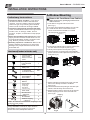
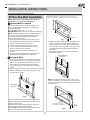
DRIVE LOCKING SCREWS
6
A: For wooden windows:
Drive 1/ 2 (12.7 mm) locking screws through the frame••
lock and into the sill (Fig.8A). NOTE: To prevent
window sill from splitting, drill 1/8 (3mm) pilot holes
before driving screws. Drive 1/ 2 (12.7mm) locking••
screws through frame holes into window sash (Fig.8B).••
B: For Vinyl-Clad windows:
Drive 1/ 2 (12.7 mm) locking screws through the frame••
lock and into the window sash (Fig.8B). NOTE: Before••
driving the screws, use a drill to drill 5 holes through••
the holes in the frame lock and frame extensions into••
the windows sash as shown (Fig. 8B).
Fig.8A Fig.8B
C.To secure lower sash in place, attach right angle
sash lock with 3/4" (19mm) or 1 screw as
shown(Fig.9).
/2" (12.7mm)
Fig.9
D.Cut and insert it in the
space between the upper and lower sashes (Fig.10).
Window sash seal foam
INSTALL R1 HARDWARE (only be
applicable to Energy star models )
7
In order to minimize air leaks and ensure optimal
insulation, it is necessary to install the included R1
hardware to the side curtain. Follow the instructions
below.
Step 1. After the unit is installed to the window,
measure the inner width of the side curtain as shown
(Fig.11).
Step 2. Remark a line on the provide R1 insulation
panel according to a length 1/8 (3mm) less than the
measured width in step 1, then cut the R1 insulation
panel along the line (Fig.12).
A: For wooden windows:
Drive 1/2” (12.7 mm) locking screws through the frame
lock and into the sill (Fig. 8A). NOTE: To prevent window
sill from splitting, drill 1/8” (3 mm) pilot holes before driving
screws. Drive 1/2” (12.7 mm) locking screws through frame
holes into window sash (Fig. 8B).
B: For Vinyl-Clad windows:
Drive 1/2” (12.7 mm) locking screws through the frame
lock and into the window sash (Fig. 8B). NOTE: Before
driving the screws, use a drill to drill 5 holes through the
holes in the frame lock and frame extensions into the win-
dow sash as shown (Fig. 8B).

Owner’s Manual - RG/RADS Series
14
INSTALLATION INSTRUCTIONS
If AC is Blocked by Storm Window
Add wood as shown in Fig.15, or remove storm
window before air conditioner is installed.
If Storm Window Frame must remain, be sure the
drain holes or slots are not caulked or painted shut.
Accumulated Rain Water or Condensation must be
allowed to drain out.
Removing AC From Window
Turn AC off, and disconnect power cord.
Remove sash seal from between windows, and
unscrew safety sash lock.
Remove screws installed through frame and frame-
lock.
Remove the R1 Panel and close (slide) side panels
into frame.
Keeping a firm grip on air conditioner, raise sash
and carefully remove.
Be carefully not to spill any remaining water while
lifting unit from window. Store parts WITH air
conditioner.
Board
thickness
as required,
for proper
pitch to rear,
along entire
sill. Fasten
with nails or
screws.
Fig.15
Storm window
frame or other
obstruction.
SASH
1-1/2"min
(38 mm)
INSTALL WEATHER STRIPPING (only
applicable to Energy star models)
7
In order to minimize air leaks between the room air••
condit••oner and the window opening, trim the
weather
st••ipping •• ••••a proper length, peel off the
protective
backing and plug any gaps if needed
(Fig.14).
Fig.14
Step 4. Repeat on the other side.
Fig.13
Step 3. Slide the R1 insulation panel into the side
curtain, the side with pattern should fac•• the indoor••
side.(Fig.13).
Step 3. Slide the R1 insulation panel into the
side curtain, the side with pattern should face the
indoor side. (Fig.13).
In order to minimize air leaks between the room air
conditioner and the window opening, trim the weather
stripping to a proper length, peel off the protective
backing and plug any gaps if needed (Fig. 14).

Owner’s Manual - RG/RADS Series
15
INSTALLATION INSTRUCTIONS(for 15000 to 18000Btu/h)
Read these instructions completely
and carefully.
IMPORTANT- Save these••
instructions for local inspector s use.
IMPORTANT- Observe all••governing
codes and ordi••ances.
Note to Installer- Be sure to leave these••
instructions with the Consumer.
Note to Consumer- Keep these••
instructions for fut• •••e reference.
Skill level- Installatio•• of this appliance••
requires basic mechanical skills.
Completion time- Approximately 1 hour.••
We recommend that two people install••
this product.
Proper installation is the responsibility
of the installer.
Product failure due to improper installation••
is not covered under the Warranty.
You MUST use all supplied parts and use••
proper installation procedures as described••
in these instructions when installing this air••
conditioner.
BEFORE YOU BEGIN
CAUTION
Do not, under any circumstances, cut or••
remove the third (ground) prong from the••
power cord.
Do not change the plug on the power cord••
of the air conditioner.
Aluminum house wiring may present special••
problems- consult a qualified elect••••cian.
When handling unit, be careful to avoid cuts from••
sharp metal edges and aluminum fins on front and••
rear coils.
Save Carton and these Installation Instructions
for future reference. The carton is the best way
to store unit during winter, or when not in use.
NOTE:
Preliminary Instructions
Do the following before starting to install unit.
See illustrations below.
Check dimensions of your unit to determine
model type:
Unit Height: 18 5/8 17 5/8
Unit Width:
Min. Window Opening:
Min. Window Width:
Max. Window Width:
26 23
1
2
/
5
8
/
19 18
1
2
/
31 28
42 40
1
2
/
1. Check window opening size-- the mounting
parts furnished with this air conditioner are
made to install in a wooden sill double-hung
window. The standard parts are for window
dimensions listed above. Open sash to a mini-
mum of 19 inches(483mm). See Fig.D.
SASH
/2 MIN.
1
19 MIN.
Storm Window Frame or
Other Obstruction
Storm Window
Frame or Other
Obstruction
Board
Thickness
As Required,
Along Entire
Stool. Fasten
With Two Nails
Or Screws.
Fig.D
Fig.E
/2 MIN.
1
/2 MIN.
1
19 MIN.
SASH
Window Sash Seal
Safety Lock and
3 /4 (or1 ) Long
Hex Head Screw
/2
Top Angle
Foam Gasket
Washer Head
Locking screw
Frame
Assembly
(Left)
Side Retainer
Bottom rail
seal to Unit
1 /2 Long
Screw and
Locknuts
Locknut
3 /4 Long
Flat Head
Bolt
Sill Angle
Bracket
Window Support
Bracket
Frame
Assembly
(Right)
1
/
2
2.Check condition of window-- all wood parts of
window must be in good shape and able to firmly
hold the needed screws. If not, make repairs
before installing unit.
Read these instructions completely and
carefully.
IMPORTANT- Save these instructions for
local inspector’s use.
IMPORTANT- Observe all governing
codes and ordinances.
Note to Installer- Be sure to leave these
instructions with the Consumer.
Note to Consumer- Keep these
instructions for future reference.
Skill level- Installation of this appliance
requires basic mechanical skills.
Completion time- Approximately 1 hour.
We recommend that two people install
this product. Proper installation is the
responsibility of the installer. Product failure
due to improper installation is not covered
under the Warranty. You MUST use all
supplied parts and use proper installation
procedures as described in these instructions
when installing this air conditioner.
Do not, under any circumstances, cut or
remove the third (ground) prong from the
power cord.
Do not change the plug on the power cord of
the air conditioner.
Aluminum house wiring may present special
problems- consult a qualied electrician.
When handling unit, be careful to avoid cuts from
sharp metal edges and aluminum ns on front and rear
coils.

Owner’s Manual - RG/RADS Series
16
INSTALLATION INSTRUCTIONS
3. Check your storm windows-- if your storm
window frame does not allow the clearance
required, correct by adding a piece of wood as
shown in Fig.E,or by removing storm window
while room air conditioner is being installed.
4 .Check for anything that could block airflow--
check area outside of window for things such as
shrubs, trees, or awnings. Inside, be sure
furniture, drapes, or blinds will not stop proper
airflow.
5.Check the available electrical service- Power
supply must be the same as that shown on the
unit serial nameplate. Power cord is 48 inches
long. Be sure you have an outlet near.
6.Carefully unpack air conditioner- Remove all
packing material. Protect floor or carpet from
damage. Two people should be used to move
and install unit.
Preliminary Instructions
Tools Required
A large flat blade screwdriver;Tape measure
Adjustable wrench or pliers;Pencil;Level
Socket wrenches;Phillips Screwdriver
Hardware(Packed with the unit)
7/16 inch Locking
screw and Flat
washer for window
panels
3 / 4 or 1/2)inch
Long Hex-head
Screw
Safety Lock
1 / 2 inch Long
screw and Locknut
3 / 4 inch Long
Flat Head Bolt
and Locknut
Sill Angle
Bracket
Long hex-head
locking screw
for top angle,
side retainer
5 /16 inch Long
2 ea.
7
1
4ea.
2ea.
2
10
Foam insert
2
Window sash
seal foam
1
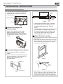
A.Window Mounting
1
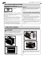
Remove Air Conditioner from Cabinet
1. Pull down front grille and remove filter.
(See Fig.1).
2. Lift front grille upwards and place to one side.
3. Locate the four front screws and remove.
These screws will be needed to re-install
the front panel (see Fig.2).
7. Remove shipping screws from top of unit and
also on the side by the base if installed
(see Fig.5).
8. Hold the cabinet while pulling on the base pan
handle, and carefully remove the unit.
9. Add two foam inserts to holes in top of cabinet
where shipping screws were removed from
(see Fig.6).
4. Push metal cabinet side to release plastic tabs
on each side of front panel (see Fig.3).
5. Gently lift front panel off unit(see Fig.3A).
6. Disconnect the connector plug of the display
panel from the unit and place front panel to one
side(see Fig.4).
Front Grille
Fig.1 Fig.2
Fig.3
Fig.3A
Front Panel
Fig.4
shipping
screws
Fig.5 Fig.6
R1 hardware
2
(10 *3/4 *1/12 )
NOET: R1 hardware and Weather stripping is only
for Energy star models.
Weather stripping
5
NOTE: Remove any packaging material from
cabinet exterior.

Owner’s Manual - RG/RADS Series
17
INSTALLATION INSTRUCTIONS
10. Your unit may come with internal packaging.
This packaging must be removed prior to
installing the air conditioner back into the
cabinet.(see Fig.7).
2
Install Top Angle and
Side Bracket
1. Attach foam gasket to top angle
above holes as shown in Fig.6.
2. Install top angle and side retainers
to cabinet as shown in Fig.8 (10 sc-
rews).
3
Assemble Window Filler Panels
1. Place cabinet on floor, a bench, or
a table.
2. Slide I section of window filler panel
into side retainer on the side of the
cabinet (see Fig.9 & Fig.10).
Do both sides.
,,
,,
Plastic
Frame
Window Filler
Panel
Side Retainer
Fig.9
5 16 long
hex-head
/
Shipping Packaging
Plastic tie
Fig.7
Fig.8
3. Insert top and bottom legs of window
filler panel frame into channel in the
top angle and bottom rail. Do both
sides.
4. Insert washer head locking 7/16" screws
(2) into holes in top leg of filler panel
frame (see step 6). Do not totally tigh-
ten. Allow leg to slide freely. Screws
will be tightened after section 6.
4
Place Cabinet in window
1.Open window and mark center of window stool as
shown(Fig.11).
2. Place cabinet in window with bottom stool angle
firmly seated over window stool as shown. Bring
window down temporarily behind top angle to
hold cabinet in place(Fig.12).
Stool
Stool
Angle
Top
View
Air Conditioner
Cabinet
Plastic
Frame
" " Section
Window
Filler
Panel
Locking
Screw
Hole
Fig.10
Fig.11
Fig.12
3. Shift cabinet left or right as needed to line up
center of cabinet on center line marked on stool.
4. Fasten cabinet to window stool with 2 screws
into holes(You may wish to pre-drill pilot holes).
5. Add bottom rail seal over screws to window stool.

Owner’s Manual - RG/RADS Series
18
INSTALLATION INSTRUCTIONS
5
Install Support Bracket
1. Hold each support bracket flush against
outside of sill, and tight to bottom of cabinet
as shown in Fig.15A. Mark brackets at top level
of sill, and remove.
2. Assemble sill angle bracket to support
brackets at the marked position(Fig.15B).
Hand tighten, but allow for any changes later.
Bottom
Rail Seal
1 2 Long Screws
And Locknuts
Left
Right
Sill Angle
Bracket
Flat Head
Bolt
2 Each Required For
Each Support Bracket
Locknut
3 4 (or1 )Long
Hex-head Screw
/2
Fig.13
Fig.15A
Mark
Fig.15B
3. Close window behind top angle.
6
Extend Window Filler Panels
1. Carefully raise window to expose filler panel
locking screws. Loosen screws so filler panels
slide easily.
2. Extend panels to fill window opening completely.
Tighten locking screws on top(Fig.17).
3. Install support brackets(with sill angle
brackets attached) to correct hole in
bottom of cabinet as shown in Fig.16.
4. Tighten all 6 bolts securely.
1 2 Long Screws
and Locknuts
Locking Screw
7/16"Locking Screw
and Washer
Fig.16
Fig.17
FIG.14
5
Side Louvers
Window Sash
Window Sill
Sill Angle Bracket
15
About1 / to1 /
4 8
Measure from
the cabinet edge.
NOTE: Check that air conditioner is tilted back about
O
(tilted about 3 t o 4 downward t o th e o utside).
After proper installation, condensate should not
drain from the overflow drain hole during••n••rmal••use,••
correct•• the slope otherwise (Fig.14).
15 O
1 / to 1 /
4 8
drain from the overow drain hole during normal use, correct
the slope otherwise (Fig. 14).
Page is loading ...
Page is loading ...
Page is loading ...
Page is loading ...
Page is loading ...
Page is loading ...
Page is loading ...
Page is loading ...
Page is loading ...
Page is loading ...
Page is loading ...
Page is loading ...
Page is loading ...
Page is loading ...
-
 1
1
-
 2
2
-
 3
3
-
 4
4
-
 5
5
-
 6
6
-
 7
7
-
 8
8
-
 9
9
-
 10
10
-
 11
11
-
 12
12
-
 13
13
-
 14
14
-
 15
15
-
 16
16
-
 17
17
-
 18
18
-
 19
19
-
 20
20
-
 21
21
-
 22
22
-
 23
23
-
 24
24
-
 25
25
-
 26
26
-
 27
27
-
 28
28
-
 29
29
-
 30
30
-
 31
31
-
 32
32
-
 33
33
-
 34
34


Century RADS-101Q Installation, Operation & Maintenance Manual
- Category
- Mobile air conditioners
- Type
- Installation, Operation & Maintenance Manual
Ask a question and I''ll find the answer in the document
Finding information in a document is now easier with AI
Related papers
-
COMFORT-AIRE RADS-253S Owner's manual
-
COMFORT-AIRE RADS Series Owner's manual
-
COMFORT-AIRE RADS-61R Installation, Operation & Maintenance Manual
-
-
-
-
-
COMFORT-AIRE PS-81D 101D Owner's manual
-
-


