
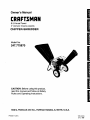
Owner's Manual
CRRFTSMAN
[]
6.5 Horse Power _]
m
3" diameter chipping capacity
CHIPPER-SHREDDER
Model No. B
247.775870
CAUTION: Before using this product,
read this manual and follow all Safety
Rules and Operating Instructions.
i
Sears, Roebuck and Co., Hoffman Estates, IL 60179, U.S.A.
Printed in U,S.A.

Content Page Content Page
Warranty Information 2 Service & Adjustment 14
Safe Operation Practices 3 Off-Season Storage 16
Assembly 5 Trouble-Shooting 17
Operation 8 Repair Parts 18
Maintenance 11
One-Year Warranty on Craftsman Chipper-Shredder
For one year from the date of purchase, when this Craftsman chipper-shredder is maintained, lubricated, and
tuned up according tothe operating and maintenance instructions inthe operator's manual, Sears will repair, free
of charge, any defect in material or workmanship.
This warranty excludes the blades, chipper blades, flails, air cleaners, spark plugs, catcher bags and tires which
are expendable parts and become worn during normal use.
If this chipper-shredder is used for commercial or rental purposes, this warranty applies for only 30 days from the
date of purchase.
WARRANTY SERVICE IS AVAILABLE BY CONTACTING THE NEAREST SEARS SERVICE CENTER INTHE
UNITED STATES. THIS WARRANTY APPLIES ONLY WHILE THIS PRODUCT IS IN USE IN THE UNITED
STATES.
This warranty gives you specific legal rights, and you may also have other rights which vary from state to state.
Sears, Roebuck and Co., D/817WA, Hoffman Estates, II60179
These accessorieswere
available when the chipper-
shredderwas purchased.
They are also available at
mostSears retailoutletsand
service centers.MostSears
storescan order repair parts
foryou when you providethe
model numberofyour
chipper-shredder.
Spark Air Engine Gas Stabilizer Tow Hitch Kit
Plug Filter Oil Can
PRODUCT
HORSEPOWER:
CRANKCASE CAPACITY:
FUEL TANK CAPACITY:
SPARK PLUG:
SPARK PLUG GAP:
SPECIFICATION
6.5 H.P.
21oz. SAE 30 ENGINE OIL
3 QUARTS (UNLEADED)
Champion (N4C)
.030
Model Number ............. 247.775870 ...........
Serial Number ...........................................................
Date of Purchase ......................................................
Record both serial number and date of purchase and
keep in a safe place for future reference.
2

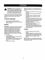
This symbol points out important safety instructions which, if not followed, could endanger the per-
sonal safety and/or property of yourself and others. Read and follow all instructions in this manual before
attempting to operate your chipper shredder. Failure to comply with these instructions may result in per-
sonal injury. When you see this symbol--heed its warning.
I Your chipper-shredder was built to be operated according to the rules for safe operation in
,_ DANGER" this manual. As with any type of power equipment, carelessness or error on the part of the oper-
_" " ator can result in serious injury. If you violate any of these rules, you may cause serious
injury to yourself or others.
,_ WARNING: The Engine Exhaustfrom this product containschemicalsknown to
the State of California to cause cancer, birth defects or other reproductive harm.
GENERAL OPERATION
Read this owner's guide carefully in its entirety before
attempting to assemble this machine. Read,
understand, and follow all instructions on the machine
and in the manual(s) before operation. Be completely
familiar with the controls and the proper use ofthe
machine before operating it. Keep this manual in a
safe place forfuture and regular reference and for
ordering replacement parts.
Your chipper-shredder is a powerful tool, nota
plaything. Therefore, exercise extreme caution at all
times. Your unit has been designed to perform two
jobs; tochip and shred vegetation found in a normal
yard. Do not use itfor any other purpose.
Never allow children under age 16 to operate the unit.
Children 16 years and older should only operate the
unit under close parental supervision. Only
responsible individuals who are familiar with these
rules ofsafe operation should be allowed to useyour
unit.
Keep ths area ofoperation clear of all persons,
particulady small children and pets. Stop the engine
when they are inthe vicinity of the unit. Keep work
area clean and clear ofbranches or obstacles which
could cause you to stumble or fall.
When feeding material intothis equipment, be
extremely careful that pieces of metal, rocks, bottles,
cans or other foreign objects are notincluded.
Personal injury ordamage to the machine could result.
Always wear safety glasses or safety goggles, during
operation and while performing an adjustment or
repair, to protect eyes from foreign objects that may be
thrown from the machine.
Wear sturdy, rough-soled work shoes and close fitting
slacks and shirt. Shirt and slacks that cover the arms
and legs and steel-toed shoes are recommended. Do
not wear loose fitting clothes orjewelry and secure hair
so it is above shoulder length. They can be caught in
moving parts. Never operate a unitin bare feet,
sandals or sneakers. Wear gloves when feeding
material in the chipper chute or shredder hopper.
Never place your hands, feet, or any part of your body
intothe shredder hopper, chipper chute, discharge
opening, or near any moving part while the engine is
3
running. Keep clear of the discharge opening at all
times. If it becomes necessary to push material into
the chipper chute or shredder hopper, use a small
diameter stick, NOT YOUR HANDS,
Ifit is necessary for any reason to unclog the feed
intake or discharge openings or to inspect or repair any
part of the machine where a moving part can come in
contact with your body or clothing, stop the machine,
allow it to cool, disconnect the spark plug wire from the
spark plug and move it away from the spark plug
before attempting to unclog, inspect or repair.
Do not operate unitwhile under the influence ofalcohol
or drugs.
The machine should only be operated on a level
surface. Never operate your uniton a slippery, wet,
muddy or icy surface. Keep your work area clean and
clear of branches or obstacles which could cause you
to stumble and fall Do not overreach. Maintaining
proper footing and balance is essential to preventing
accidents.
Do not allow an accumulation of processed material to
build-up in the discharge area as this will prevent
proper discharge and can result in kick-back from the
chipper chute.
Keep your face and body back from chipper chute to
avoid accidental bounce back of any material.
Do not transport machine while engine is running.
Ifthe cutting mechanism strikes a foreign object or if
your machine should start making an unusual noise or
vibration, immediately stopthe engine and allow the
machine to come to a complete stop. Disconnect the
spark plug wire and move it away from the spark plug.
Take the following steps.
a. inspect fordamage.
b. Repair or replace any damaged parts.
c. Check for any loose parts and tighten to assure
continued safe operation.
Never attempt to attach or remove catcher bag when
engine is running. Shut the engine off and wait for the
impeller to come to a complete stop. The impeller
continues to rotate for a few seconds after the engine is
shut off. Never place any part of the body in the
impeller area until you are sure the impeller has
stopped rotating.
Muffler and engine become hot and can cause a burn.
Do not touch.

Do not ailow leaves or other debris to build-up on
engine's muffler. The debris could ignite and cause a
fire.
Do not attempt to shred or chip material larger than
specified in this manual. Personal injuryor damage
to the machine could result.
Do not operate engine if air cleaner or cover over
carburetor air-intake is removed, except for
adjustment, Removal of such parts could create a fire
hazard.
Only use accessories approved for this machine by
the manufacturer. Read, understand, and follow all
instructions provided with the approved accessory.
If situations occur which are not covered by this
manual, use care and good judgment. Contact your
dealer for assistance.
Keep discharge discharge chute, chipper chute door,
and ell other guards end safety devices in place and
operating properly.
Only operate unit in good daylight. Do not operate
unit at night or in dark areas where your vision may be
impaired.
CHILDREN
Tragic accidents can occur if the operator is notalert to the
presence of small children. Children are often attracted to
the chipper-shredder and the chipping and shredding
activity. Never assume that children will remain where you
last saw them.
Keep children out of the work area and under the
watchful eye of a responsible adult other than the
operator.
Be alert and turn the unit off if a childenters the area.
• Never allow children under the age of 16 to operate
the chipper-shredder.
SERVICE
Use extreme care in handling gasoline end other
fuels. They are extremely flammable and the vapors
are explosive.
a. Store fuel and oil in approved containers, away
from heat and open flame, and out of the reach
of children. Check and add fuel before starting
the engine. Never remove gas cap or add fuel
while the engine isrunning. Allow engine to
cool at least two minutes before refueling.
b. Replace gasoline cap securely and wipe off any
spilled gasoline before starting the engine as it
may cause a fire or explosion.
c. Extinguish all cigarettes, cigars, pipes and other
sources of ignition.
d. Never refuel unit indoors because flammable
vapors will accumulate in the area.
e. Never store the machine or fuel container inside
where there is an open flame or spark such as a
gas hot water heater, space heater, clothes
dryer or furnace.
Never run your machine in an enclosed area as the
exhaust from the engine contains carbon monoxide,
which is an odorless, tasteless and deadly poisonous
gas.
To reduce fire hazard, keep engine and muffler free of
leaves, grass, and other debris build-up. Clean up
fuel and oil spillage. Allow unit to cool at least 5
minutes before storing.
Before cleaning, repairing, or inspecting, make certain
the impeller and all moving parts have stopped.
Disconnect the spark plug wire and keep wire away
from spark plug to prevent accidental starting. Do not
use flammable solutions to clean air filter.
Check the blade and engine mounting screws at
frequent intervals for proper tightness. Also visually
inspect blades for wear and/or damage (e.g., bent,
cracked). Replace with blades which meet original
equipment specifications.
Keep all nuts, bolts, and screws tight to be sure the
equipment isin safe working condition.
Never tamper with safety devices. Check their proper
operation regularly.
After stdkinge foreign object, immediately stop the
engine, disconnect the spark plug wire from the spark
plug, end thoroughly inspect the unit for any damage.
Repair damage before starting and operating unit.
Do not alter or tamper with the engine's governor
setting. The governor controls the maximum safe
operating speed of the engine. Over-speeding the
engine is dangerous and will cause damage to the
engine and to other moving parts of the machine.
YOUR RESPONSIBILITY
Restrict the use of this power machine to
persons who read, understand and follow the
warnings and instructions inthis manual and on
the machine.
SAVE THESE INSTRUCTIONS
FOR FUTURE REFERENCE.
This unit is equipped with an internal combustion engine and should not be used on or near any unimproved forest-
covered, brush-covered orgrass-covered land unless the engine's exhaust system is equipped with a spark arrester
meeting applicable local or state laws (if any). If a spark arrester isused, itshould be maintained in effective working
order by the operator.
In the State of California the above isrequired by law (Section 4442 ofthe California Public Resources Code). Other
states may have similar laws. Federal laws apply on federal lands. A spark arrester for the muffler is available
through your nearest Sears Authorized Service Center (See the REPAIR PARTS section of this manual.)
4

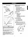
Carton Contents
Hopper
Discharge Chute
Catcher Bag
__Bottle
of Oii
Chipper Chute
• You will find the hopper in the top insert inside the carton.
Figure 1
IMPORTANT: This unitis shipped without gasoline
or oil in the engine. After assembly, see OPERATION
section of this manual for proper fuel and engine oil
fill-up.
NOTE: To determine right and left hand sides ofyour
chipper-shredder, stand behind the unit with the
engine farthest away from you.
Your chipper-shredder has been completely assembled
at thefactory, exceptfor the hopperassembly,
discharge chute and thecatcher bag.
These parts are shipped loose in the carton. A pair of
safety glasses and a bottle of oilare also included in
the carton.
REMOVE CHIPPER-SHREDDER
FROM CARTON
• Cut the corners of the carton.
• Remove all packing inserts.
• Remove all loose parts including owner's
manual. See figure 1.
• Roll chipper-shredder out of the carton.
• Make certain all parts and literature have been
removed before the carton is discarded.
LOOSE PARTS
(Refer to figure 1.)
a. Hopper Assembly
b. Discharge Chute
c. Catcher Bag
d. Bottleof Oil
e. Safety Glasses (not shown infigure 1)
f. Owner's Manual (not shown infigure 1)
g. Chipper Chute
TOOLS REQUIRED
1. 1/2" or Adjustable Wrenches
2. 7/16" or Adjustable Wrenches
3. 9/16" or Adjustable Wrenches
4. Funnel
DISCONNECTING SPARK PLUG
Disconnect the spark plug wire and move it
away from the spark plug before assembling the
chipper-shredder. See figure 2.
Spark
Wire
Figure 2
5

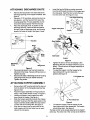
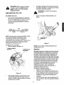
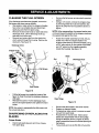
ATTACHING DISCHARGE CHUTE
• Remove the wing knobs from each side ofthe
discharge opening on the chipper-shredder. See
figure 3.
• Using two 7/16" wrenches, remove hex lock nut,
two spacers, and the hex bolt from top ofthe
housing assembly. For easy assembly, do not
remove the second spacer from the hex bolt.
• Place the discharge chute in position on the
discharge opening. Insert hex boltand spacer
through hinge on discharge chute and housing
(spacer fits inside of hinge). See figure 3 inset.
Insert the hex bolt (that you earlier removed)
from the left through the hole on the hopper and
the inlet guide. Insert the hex nut onto the bolt
from the other side. See figure 4 inset.
Hopper Pivot Door
Inlet G_
Nu1
Hex Nut
-- Hex Bolt
Hinge
Sto:
Wing
Knob
Discharge
Chute
tg Knob
Figure 3
Place second spacer over hex bolt inside the
other half ofthe hinge. Secure with hex lock nut.
Tighten securely.
Secure both sides of discharge chute to housing
using wing knobs that you earlier removed.
Tighten wing knobs.
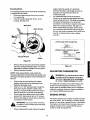
ATTACHING HOPPER ASSEMBLY
• Remove the 8-3/8" long hex boltand the hex nut
from the bottom of the inlet guide opening. See
figure 4 inset.
• Place the hopper assembly on the ground and
hold itin the position shown in step 1 in figure 4.
• Holding the hopper, push hopper pivot door
down inside the hopper. See figure 4.
• Slide the hopper assembly towards the chipper-
shredder housing so that the upper guide on the
hopper assembly slides under the stop washer
on each side ofthe inletguide. See figure 4.
• Alignthe two holes (one on each side) of the
lower hopper with the two holes (one on each
side) ofthe inlet guide.
Inlet Guide
Hopper
Figure 4
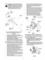
Tighten the boltto remove all sideplay ( after
tightening the bolt, the hopper willpivot up and
down). This will secure the hopper assembly to
the inletguide.
To raise the hopper, hold the hopper by the
hand-hold and lift itup tillitclicks into
position.See figure 5.
1. Lift
2. Pull release bar
Figure 5
• To Iowerthe hopper, hold the hopper by the
hand-hold and pull the release bar. The hopper
should drop down. See figure 5.
The flap control rod isalready attached to the hopper
at the top. The other end of the rodhas to be attached
6

to the stop washer on the inlet guide. See figure 6.
,_ WARNING: This flap control rod is a safety
device to hold the flap in place inside the
hopper while shredding branches. Do not
operate the chipper-shredder without
properly attaching this flap control rod.
Hopper
Attach flap
control rod f
here
and hex nuts that you earlier removed• Do not
tighten the nuts at this time. Make sure to place
the cupped side ofthe washer against the
chipper chute.
• Align the holestowards the front opening ofthe
chute with the holes on the brace. See figure 7.
• Insert one each ofthe hex bolts, lock nuts, and
flat washers (that you earlier removed) through
each hole inthe chute and the brace. Tighten
these boltsto secure brace to the chute.
• Tighten bolts securingthe brace tothe lower
frame. These boltshad been removedearlier.
• Tighten the three nuts on the weld studs.
Chipper
Chute
Cw::::-
Weld Stud
Weld Stud
Flap Control
Rod
* Do notremovethese hardwarefromthe inletguide
assembly whileattachingtheflap controlrod.
Figure 6
• Raise the hopper tillit clicks intoposition.
• Unscrew the shoulder bolt from the stop washer
on the inletguide. See figure 6.
• Align the loose end of the flap control rodwith
the stop washer on the inlet guide.
• Slide the shoulder bolt through the opening in
the flap control rod. Secure tightly.See figure 6.
ATTACHING THE CHIPPER CHUTE
• Your unit isshipped with one end of the brace
already secured tothe lowerframe. Loosen the
bolts securing the brace to the frame.
• Remove the three cupped washers and hex
nuts from the weld studs beside the opening on
the leftside ofthe housing. See figure 7.
• Remove the two sets of hex bolt, lock nut, and
flat washer from the two holes on the upper end
of the brace as shown in figure 7.
• Place the chipper chute over the weld studs so
the sloton the chute istowards the bottom. Align
the three holes at the bottom of the chute with
the three weld studs.
• Secure with the three pairs of cupped washers
Washer
Chute
Brace
Figure 7
ATTACHING THE CATCHER BAG
Your chipper-shredder isequipped with a catcher bag
to catch the shredded material.
• To attach the bag, place the bag opening over
the discharge chute so it completely covers the
discharge chute and goes over the chute
flanges.
• Depress the plunger on the draw-string, and pull
on the drew-string until the bag istight around
the chute opening. Release plunger to lockitinto
position. See figure 8.
Drawstring
Bag
Figure 8

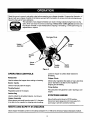
I
Read this owner's manual and safety rules before operating your chipper-shredder. Compare the illustration in I
figure9withy_urchipper_shreddert_fami_iarizey_urselfwiththe__cati_n_fVari_usc_ntr__sandadjustments_ _1
Save this manual for future reference. I
The operation of any chipper-shredder can result in foreign objects being thrown intothe
eyes, which can resultin severe eye damage. Always wear safety glasses provided w th
the chipper-shredder or eye shields before chipping or shredding, or while performing any
adjustments or repairs.
Discharge Chute
Hopper f Chipper
Assembly Chute
Release
Bar
Primer
Button
Figure 9
Throttle Starter
Control Handle
OPERATING CONTROLS
Release Bar
Used to release the hopper when raising or lowering.
Starter Handle
Used to manually start the engine.
Throttle Control
Regulates speed ofthe engine.
Catcher Bag
Used to collect the shredded material. (not shown)
Hopper Assembly
Allows leaves and small branches upto 0.5 "diameter
to be fed into the impeller for chipping and shredding.
Lower the hopper to collect raked materiat for
shredding.
Chipper Chute
Allows bulky vegetation like stalks or heavy branches
upto3" diameter to be fed intothe impeller for
chipping and shredding.
Primer Button
Fills carburetor with gasoline to aid in starting a cold
engine.
STOPPING ENGINE
Move throttle control lever to STOP position.
Disconnect spark plug wire and move away from
spark plug to prevent accidental starting.
MEETS ANSI SAFETY STANDARDS
Sears chipper-shreddersconformtothe safetystandard B 71.6 -1990 ofthe American National Standards Institute.
8

&
WARNING: Before using yourchipper-
shredder, refer to the safety rules on
pages 3 and 4 of this manual again.
Always be careful.
GAS AND OIL FILL-UP
Oil (Packed with unit)
• Only use high quality detergent oil rated with
API service classification SF, SG or SH. Select
the oil's viscosity grade according to your
expected operating temperature. Follow the
chart below.
Co der _ 32°F _ Warmer
_.==_.o L
5W30 I SAE 30
NOTE: Although multi-viscosity oils (5W30, 10W30,
etc.) improve starting in cold weather, these
multiviseosity oils willresult in increased oil
consumption when used above 32°[::. Check the oil
level more frequently toavoid possible engine
damage from running low on oil.
Fillengine with oil as follows.
• Remove dipstick. See figure 10.
1. Remove dipstick
end fill oll
2. Remove cap
and fill gas
F
Figure 10
With chipper-shredder on level ground, use a
funnel to fillengine with oilto FULL mark on
dipstick. Capacity is approximately 20 ounces.
Be careful not to overfill.
Tiltchipper-shreddertowardthe left (from behind
the hopper). See figure 11.Check oillevel. Put the
unitbackon the groundcarefully.
,_ WARNING: Do not tilt unit holdingthe
hand-hold.
Add oil if necessary. Replace dipstick and
tighten.
Hold unit this
to tilt
Figure 11
NOTE: Do not overfill. Oil bottle packed with unit
contains 20 oz. of oil.
Gasoline
Warning: Experience indicates that alcohol blended
fuels (called gasohol or using ethanol or methanol)
can attract moisture which leads to separation and
formation of acids during storage. Acidic gas can
damage the fuel system of an engine while instorage.
To avoid engine problems, the fuel system should be
emptied before storage for 30 days or longer. Drain
the gas tank, startthe engine and let itrun until the
fuel lines and carburetor are empty. Use fresh fuel
next season. See STORAGE instructionsfor
additional information. Never use engine or
carburetor cleaner products inthe fuel tank or
permanent damage may occur.
Fill gas tank with gas as follows.
• Remove fuel cap. See figure 10.
• Make sure the container (from which you will
pour the gasoline) isclean and free from rust or
foreign particles. Never use gasoline that may
be stale from long periods of storage inthe
container.
• Fill fuel tank with fresh, lead-free gasoline. DO
NOT use Ethyl or high octane gasoline.Replace
fuel cap.

WARNING:Do not fill closer than 1/2 inch
oftop of fuel tank to prevent spills and to
allow for fuel expansion. If gasoline is
accidently spilled, move chipper-shredder
away from area of spill.Avoid creating any
source of ignition until gasoline vapors have
disappeared.
Check the fuel level periodically to avoid
running out of gasoline while operating the
chipper-shredder.
If the unit runs out of gas as itis shredding or
chipping, it may be necessary to unclog the unit
before itcan be restarted. Refer to Removing
the Flail Screen in SERVICE AND
ADJUSTMENT section.
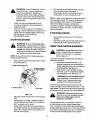
STARTING ENGINE
WARNING: Be sure no one other than
the operator is standing near the chipper-
shredder while starting or operating. Do not
operate this chipper-shradder unless the
discharge chute has been properly installed
and is secured with the hand knobs.
NOTE: To prevent the unitfrom sliding,place your
foot firmlyagainst the tire.
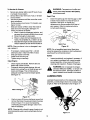
Attach spark plug wire and rubber boot to spark
plug. See figure 12.
1. Attach spark plug wire
2. Place Throttle
in Fast Position
3. Prime 3 times
4. Pull rope
Figure 12
• Place the throttle control lever in FAST position
(UP).
• Push primer 2 or 3 times, waiting a couple of
seconds between each push. In cold weather
(50°F or below) prime 5 times.
• Grasp starter handle and pull rope out slowly
until engine reaches start of compression cycle
(rope will pull slightly harder at this point). Let
the rope rewind slowly.
• Pull rope with a rapid full arm stroke. Let rope
return to starter slowly. See figure 12.
• When engine starts, move throttle control to
IDLE position for a few minuteswarm-up.
NOTE: A noise will be heard when finding the start of
the compression cycle. This noise is caused by the
flails and fingers which are part of the shredding
mechanism falling intoplace, and should be
expected. In addition, the flailsand fingers will be
noisy after the engine is started, until the impeller
reaches furlspeed.
STOPPING ENGINE
• Move throttle control lever to STOP position
(DOWN).
• Disconnect spark plugwire and move away from
spark plug to prevent accidental starting.
USING YOUR CHIPPER-SHREDDER
WARNING: Do not attempt to shred or
chipany material other than vegetation
found in a normal yard (i.e., branches,
leaves, twigs, etc.).
The chipper-shredder is designed for two different
methods ofoperation.
a. Leaves and small branches up to 1/2"
diameter (maximum) can be fed intothe
hopper assembly when itis inthe raised or
lowered position. See figure 13.
b. Bulky material, such as stalks or heavy
branches, up to3" in diameter can be fed
intothe chipper chute. See figure 13.
WARNING: Do not put material larger
than is specified intothe hopper or the
chipper chute. Personal injuryand/or
damage to the machine could result.
If it becomes necessary to push material intothe
chipper-shredder, use a small diameter stick-- not
your hands, The stick should be small enough that it
will be ground up ifit gets intothe impeller assembly.
WARNING: Never remove discharge
chute tillthe unithas completely stopped.
Never turn off the engine until all
chipping is completed,
For best performance, it isimportant to keep the
shredding blade and the chipper blades sharp.
If the composition of the material being discharged
changes (becomes stringy, etc.) or if the rate at which
the material is discharged slows down considerably, it
is likely that the shredding blade and/or chipper
10

blades are dull and need to be sharpened or
replaced. To sharpen or replace the blades, refer to
Service and Adjustments section.
IMPORTANT: There isa flail screen located inside
the housing in the discharge area. Ifthe flail screen
becomes clogged, remove and clean as instructed in
the Service and Adjustments section on page 14.
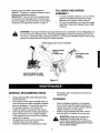
TO LOWER THE HOPPER
ASSEMBLY
• To lower the hopper assembly, use one hand to
grasp the hand-hold at the top ofthe hopper
assembly and lift slightly. Refer to figure 5.
• Pull up on the release bar, and lower the hopper
assembly tothe ground. Release the bar. Refer
to figure 5.
WARNING: The chipper-shredder discharges materials with considerable velocity. Keep away from
the area around the discharge chute. Always stop the engine and disconnect spark plug wire when
removing or attaching the bag, changing containers, or removing the shredded material. Wear safety
glasses and gloves whenever using your chipper-shredder.
Shred material upto 112 inch in diameter
\
Figure 13
GENERAL RECOMMENDATIONS
• Always observe safety rules when performing
any maintenance.
• The warranty on this chipper shredder does not
cover items that have been subjected to operator
abuse or negligence. To receive full value from
the warranty, operator must maintain the
chipper-shredder as instructed in this manual.
• Some adjustments willbe needed periodically for
proper maintenance ofyour chipper shredder.
These adjustments are covered inthe following
section of this manual.
• All adjustments mentioned here should be
checked at least once each season.
• Follow the maintenance schedule given below.
Periodically check all fasteners and make sure
these are tight.
CLEANING
• Clean the chipper-shredder by running water
from a hose through the hopper assembly and
chipper chute with the engine running. Allow the
chipper-shredder to dry thoroughly.
• Wash the bag periodically with water. Allow to
dry thoroughly in the shade. Do not use heat.
WARNING: Always stop the engine and
disconnect the spark plug wire before
performingany maintenance oradjustments.
Never remove discharge chute tilltheengine
hascompletely stopped.
11

ENGINE MAINTENANCE
Engine Oil
• Only use high quality detergent oilrated with
API service classification SF, SG or SH. Select
the oil's viscosity grade according to your
expected operating temperature. Refer to page
9 of this manual for viscosity chart.
• The four-cycle engine of your chipper-shredder
will normally consume some oil. Therefore,
check engine oil level regularly approximately
every five hours of operation and before each
usage.
• Stop engine and wait several minutes before
checking oil level. With engine on level ground,
the oil must be to FULL mark on dipstick.
• Change engine oil after the first five hours of
operation, and every twenty-five hours
thereafter.
To Drain Oil
Drain oilwhile engine is warm. Follow the instructions
given below.
• Remove oil drain plug. Catch oil in a suitable
container.
• When engine is drained of all oil, replace drain
plug securely.
• Refill with fresh oil. Refer to GAS AND OIL FILL-
UP section. Replace dipstick.
Air Cleaner
The air cleaner prevents damaging dirt, dust, etc.,
from entering the carburetor and being forced intothe
engine and is important to engine life and
performance. The air cleaner consistsof a pre-
cleaner or foam filter, and a paper filter. Never run
the engine without air cleaner completely assembled.
-- Wing Nut
_Cover
Base
/
Paper Filter
/ Pre-Cleaner
Figure 14
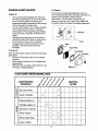
CUSTOMER RESPONSIBILITIES
MAINTENANCE _# @'_ _ ,@ ,,_ _ SERVICE
I--
Oil pivot points
0
Clean shredder _
Check engine oil _
Change engine oil _
LU
z
Service air cleaner
z
LU
Clean engine _
Reset spark plug _
Clean muffler
12

To Service Air Cleaner:
1. Service pre-cleaner after every 25 hours of use,
or at least once a season.
2. Service filter every 100 hours of use, or at least
once a season.
3. Service pre-cleaner and filter more often under
dusty conditions.
Remove wing nut and cover. For location, see
figure 14 inset.
Slide pre-cleaner offfilter. Clean the inside of
base and cover thoroughly. See figure 14.
• Clean pre-cleaner as follows:
c. Wash inwater and detergent solution, and
squeeze (donottwist)untilalldirtisremoved.
d. Rinse thoroughly in clear water.
e. Wrap in a clean clothand squeeze (do not
twist) untilcompletely dry,or allowtoair dry.
f. Saturate with engine oiland squeeze (don't
twist) to distributeoiland remove excess oil.
NOTE: If the pre-cleaner is torn or damaged in any
way, replace it,
• If necessary, replace paper filter---do not
attempt to clean. Install new filter on base.
• Slide pre-cleaner over filter.
• Install cover and wing nut.
• Tighten wing nut securely.
Clean Engine
• Clean engine periodically. Remove dirtand
debris with a clothor brush.
• Frequently remove grass clippings, dirt and
debris from cooling fins, air intake screen and
levers and linkage. This will help ensure
adequate cooling and correct engine speed.
See figure 15.
_1_ WARNING: Temperature ofmuffler andnearby areas may exceed 150° F(65°C).
Avoid these areas.
Spark Plug
Clean the spark plug and reset the gap to .030"
at least once a season or every 50 hours of
operation. See figure 16. Spark plug
replacement is recommended at the start of
each season. Refer to engine parts list for
correct spark plug type.
.030" Feeler
_ Guage
g
Figure 16
NOTE: Do not sandblast spark plug. Spark plug
should be cleaned by scraping or wire brushing and
washing with a commercial solvent.
Muffler
Inspect periodically, and replace if necessary. If
your engine is equipped with a spark arrester
screen assembly, remove every 50 hours for
cleaning and inspection. Replace ifdamaged.
WARNING: Do not operate the chipper-
shredder without a muffler, or tamper with
the exhaust system. Damaged mufflers or
spark arresters could create a fire hazard.
LUBRICATION
Lubricate the pivot points on the release bar, hopper
assembly, and discharge chute once a season using
a light oil. Refer to the lubrication chart in figure 17.
Clean cooling
Figure 15
Yearly or every 25 hours, whichever occursfirst,
remove the blower housing and clean the areas
shown in figure 15 to avoid overspeeding,
overheating and engine damage. Clean more
often if necessary.
NOTE: Cleaning with a forceful spray of water is not
recommended as water could contaminate the fuel
system.
Figure 17
13

CLEANING THE FLAIL SCREEN
Ifthe discharge area becomes clogged, remove the
flail screen and clean area as follows.
• Stop engine, make certain the chipper-shredder
has come to a complete stop and disconnect
spark plug wire from the spark plug.
• Remove the two hand knobs on each side of the
discharge chute. Liftthe discharge chute up,
and keep itout ofthe way.
• Remove two hairpin clips from the clevis pins
which extend through the housing. Remove the
clevis pins. See figure 18.
Discharge Chute
Chipper Chute_'
Hairpin
Clips,
Clevis
Pins
Screen
Hexl=ut,
Washer
Knobs
Figure 18
• Pul!theflailscreen from insidethe housing.See
figure 18. Clean the screen byscraping or washing
withwater.
• Reinstall the screen. Put the discharge chute
back to itsoriginal position and tighten the hand
knobs.
NOTE: Be certain toreassemble the flail screen with
the curved side down.
SHARPENING OR REPLACING THE
BLADES
Chipper Blades
• Disconnect spark plug wire and move it away
from spark plug.
Remove the flailscreen as instructed in previous
section.
Using a 1/2" wrench, remove the chipper chute
by removing three hex nuts and washers. See
figure 18. (Only two hex nut positions shown in
figure.)
NOTE: When reassembling, the cupped washer goes
on theslot toward the bottom of thechipper chute with
the cupped side against the chute.
Rotate the impeller assembly by hand until you
locate one of the two chipper blades in the
chipper chute opening. Remove the blade, using
a 3/16" allen wrench on the outside of the blade
and 1/2" wrench on the impeller assembly
(inside the housing). See figure 19.
Slot
Blade
Discharge Chute
Figure 19
14
Remove the other blade in the same manner.
Replace or sharpen blades.
If sharpening, make certain to remove an equal
amount from each blade.
Reassemble in reverse order. Make certain
blades are reassembled with the sharp edge
facing the direction shown infigure 19 (sharp
edge is assembled toward the slotted opening at
the bottom).
Torque boltsand nuts to 250-350 inch-pounds.

ShreddingBlade
Theshreddingblade may be removed for sharpening
or replacement as follows.
• Disconnect spark plug wire and move itaway
from spark plug.
• Lower the hopper assembly. Block up the
housing. See figure 20.
Weld Bolt
Allen Screws
Pipe
Blade
Figure 20
• Remove the sixhex lock nuts and lockwashers
from the housing weld bolts using a 1/2" wrench.
Separate the chipper-shredder intotwo halves.
• Remove the back-up plate.
NOTE: When reassembling, make certain the
embossed tab faces inward towards the impeller, and
opening on the back-up plate is toward thebottom of
the unit.
• Remove the two hand knobs and cupped
washers which secure the discharge chute.
Raise the discharge chute.
• Insert a 1/2" or 3/4" diameter pipe through the
flail screen intothe impeller to keep itfrom
turning, or remove the flail screen and insert a
piece ofwood (2 x 4) intothe chute opening.
• Remove the two outside screws on the blade,
using a 3/16" allen wrench and a 1/2" wrench.
• Remove the blade by removing the center bolt,
lock washer and flat washer.
_hL WARNING: Use caution when removing
the blade toavoid contacting the weld bolts
on the housing.
• When sharpening the blade, follow the original
angle of grind as a guide. It isextremely
important that each cutting edge receives an
equal amount of grinding to prevent an
unbalanced blade.
An unbalanced blade willcause excessive
vibrationwhen rotatingat highspeeds and may
cause damage totheunit.The bladecan be tested
for balance by balancing iton a roundshaft
screwdriver ornail. Remove metal from the heavy
side untilitisbalanced evenly. See figure 21.
When reassembling the blade, tighten center
boltto between 550 and 650 inch-pounds and
the two outer bolts tobetween 250 and 350 inch-
pounds, or lacking torque wrench, tighten
securely.
I. Insert screw driver through hole
d./
2. Blade should be parallel to ground
Scre_
Driver'_ Blade
_1 o' ol--
Ground
Figure 21
ADJUSTING CARBURETOR
WARNING: If any adjustmentsare made to
the engine whilethe engine isrunning(e.g.
carburetor),keep clear of all moving parts.
Be carefulofheated surfaces and muffler.
The carburetor has been pre-set at the factory and
should not require adjustment. However, if your
engine does not operate properly due to suspected
carburetor problems, take your chipper-shredder to
your nearest SEARS service center.
ENGINE SPEED
The engine speed on yourchipper-shredder has been
set at the factory. Do not attempt to increase engine
speed or itmay resultin personal injury. If you believe
the engine is runningtoo fast or too slow, take your
chipper-shredder to the nearest SEARS service
center for repair and adjustment.
15

A
WARNING: Never store machine with fuel
in the fuel tank inside of building where
fumes may reach an open flame or spark,
or where ignitionsources are present such
as hot water and space heaters, furnaces,
clothes dryers, stoves, electric motors, etc.
A yearly check-up by your local Sears service center
is a good way to make certain your chipper-shredder
will provide maximum performance for the next
season.
CHIPPER-SHREDDER
Clean the chipper-shredder thoroughly.
Wipe unit with an oiled rag to prevent rust (use a
lightoil or silicone).
ENGINE
IMPORTANT: Itis important to prevent gum deposits
from forming in essential fuel system parts such as
carburetor, fuel filter, fuel hose, or tank during
storage. Also, experience indicates that alcohol
blended fuels (called gasohol or using ethanol or
methanol) can attract moisture which leads to
separation and formation ofacids during storage.
Acidic gas can damage the fuel system of an engine
while in storage.
• Drain the fuel tank.
• Start the engine and let it rununtil the fuel lines
and carburetor are empty.
• Never use engine or carburetor cleaner products
inthe fuel tank or permanent damage may
Occur,
• Use fresh fuel next season.
NOTE: Fuel stabilizer is an acceptable a/temative in
minimizing the formation of fuel gum deposits during
storage.
• Add stabilizer to gasoline in fuel tank or storage
container.
• Always follow the mix ratio found on stabilizer
container.
• Run engine at least 10 minutes after adding
stabilizer to allow the stabilizer to reach the
carburetor.
• Do not drain the gas tank and carburetor if using
fuel stabilizer. Drain all the oil from the crankcase
(this should be done after the engine has been
operated and is stillwarm) and refill the
crankcase with fresh oil.
• If you have drained the fuel tank, protect the
inside of the engine as follows.
• Remove spark plug, pour approximately 1/2
ounce (approximately one tablespoon) of engine
oil into cylinder and crank slowly to distribute oil.
• Replace spark plug.
OTHER
Do not store gasoline from one season to
another.
Replace your gasoline can ifyour can starts to
rust. Rust and/or dirtin your gasoline will cause
problems. Store unit in a clean, dry area. Do not
store next to corrosive materials, such as
fertilizer.
NOTE: Ifstoring in an unventilated or metal storage
shed, be certain torustproof the equipment by coating
with a light oilor silicone.
16

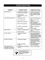
PROBLEM
Engine fails to start
Loss of power; operation erratic
Engine overheats
Too much vibration
Unit does not discharge
Rate of discharge slows
considerably or composition of
discharged material changes
POSSIBLE CAUSE
1. Fuel tank empty, or stale fuel
2. Spark plug wire disconnected
3. Faulty spark plug
4. Throttle control not in correct
position
1. Spark plug wire loose
2. Unit running on Choke
3. Blocked fuel line or stale fuel
4. Water or dirt in fuel system
5. Carburetor out of adjustment
6. Dirty air cleaner
1. Carburetor not adjusted properly
2. Engine oil level low
1. Loose parts or damaged
impeller
1. Discharge chute clogged
2. Foreign object lodged in
impeller
1. Shredding blade and/or chipping
blade dull
CORRECTIVE ACTION
1. Fill tank with clean, fresh fuel
2. Connect wire to spark plug.
3. Clean, adjust gap or replace.
4. Move throttle control to FAST
position
1. Connect and tighten spark plug
wire.
2. Move choke lever to OFF
position.
3. Clean fuel line; fill tank with
clean, fresh gasoline.
4. Disconnect fuel line at carburetor
to drain fuel tank. Refill with fresh
fuel.
5. Contact your SEARS service
center.
6. Service air cleaner.
1. Contact your SEARS service
center.
2. Fillcrankcase with proper oil.
1. Stop engine immediately and
disconnect spark plug wire.
Tighten all bolts and nuts. Make
all necessary repairs. If vibration
continues, have unit serviced by
a SEARS service center.
1. Stop engine immediately and
disconnect spark plug wire.
clean flailscreen and inside of
blower housing.
2. Stop engine immediately and
disconnect spark plug wire.
Remove lodged object.
1. Sharpen or replace blade(s).
For repairs beyond the minor
adjustments listed above, please
contact your nearest SEARS
service center.
17

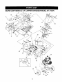
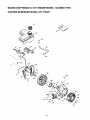
SEARS CRAFTSMAN 6.5 H.P. CHIPPER-SHREDDER MODEL 247.775870
29
,/62
66
\
8
13
17
48
64
42
42
j 'i
53
58
18

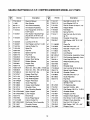
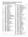
SEARS CRAFTSMAN 6.5 H.P. CHIPPER-SHREDDER MODEL 247.775870
Key
No
1
2
3
4
6
7
8
9
10
11
12
13
14
15
16
17
18
19
20
21
22
23
24
25
26
27
28
29
30
31
32
33
34
35
36
37
Pe_ No
770-1231A
_11480
681-0111
681-0144
710-0542
710-0607
710-3256
712-0429
712-3027
714-0104
715-0129
726-0106
726-0135
728-0175
732-0546
732-0629
735-0127
735-0651
736-0119
738-0137A
738-0946
747-0531A
747-0747
747-1124
747-1125
781-0492A
781-0633
781-0698
781-0715
781-0752
781-0754-0483
781-0755-0483
720-0170
750-0793
714-0149B
681-0094-0483
781-0457
681-0030
Description
Owner's Manual
Stop Washer
Inlet Guide Assembly
Arm Bracket Assembly
Hex Flange Bolt: 5/16-18 x
8.375" (gr.5)
Hex Washer Head Self-Tap-
ping Screw: 5/16-18 x 0,5"
Button-Head Screw 1/4-20 x
0.5"
Lock Nut: 5/16-18
Hex Flange Lock Nut: 1/4-20
Internal Cotter Pin
Spiral Pin
Cap Nut
Speed Cap Nut
Pop Rivet
Torsion Spring
Hopper Door Spring
Rubber Washer
Hopper Flap
Lock Washer
Shdr. Scr: .340 x .285 x 1/4-20
Shdr. Scr: .56 x ,165 x 5/16-18
Ret. Rod: 5/16" dia.
Hopper Door Rod
Flap Retaining Rod
Flap Retaining Bail
Hopper Pivot Door
Chute Flap Strip
Hopper Lock Bracket
Shredder Plate
Flap Mounting Bracket
Upper Hopper
Lower Hopper
Hand Knob
Chute Hinge Spacer
Internal Cotter Pin
Discharge Chute Assembly
Shredder Screen
impeller Assembly
Key Pa_ No
No
38 710-0157
39 736-0119
40 710-1054
41 781-0490
42 719-0329
43 715-0166
44 712-0411
45 735-0249
46 736-0247
47 711-0833B
48 710-3008
49 710-0825
50 711-0835
51 736-0217
52 681-0004A
53 681-0117
54 726-0214
55 734-1600
56 750-0786
57 738-0814
58 712-3004A
59 736-0170
60 781-0510B
61 710-0805
62 761-0633
63 728-0175
64
65 781-0735
66 710-0751
67 736-0173
68 742-0571
69 712-3027
70 749-1004
71 710-0106
72 681-0068
73 712-3010
74 736-0242
75 731-1899
Description
Hex Bolt 5/16-24 X .75"
Lock Washer 5/16" Id
Flat Hd. Screw 5/16-24 X .75"
Chipper Blade
Flail Blade
Spring Roll Pin
Hex Top Lock Nut 5/16-24
(gr. 5)
Shredder Chute Flap
Flat Washer .406" ID X 1.25"
OD
Clevis Pin
Hex Bolt5/16-18 X 1.5"
Hex Bolt 1/4-20 X 3.75"
Clevis Pin
Lock Washer
Flail Housing Assembly: Outer
Flail Housing Assembly: Inner
Push Cap 5/8" Dia,
Wheel Assembly Comp.
Spacer
Shredder Axle
Hex Lock Nut 5/16-18 (Gr.5)
Special Lock Washer
Shredder Frame
Hex Bolt5/16-18 x 1.5"
Chute Flap Strip
Pop Rivet
Engine: Tecumseh 6.5 hp.
OHH65-71701
Pin Retaining Clip
Hex Bolt 1/4-20 x .625
Flat Washer .28 I.D. x .74 O.D.
Shredder Blade
Flanged Lock Nut
Chipper Chute Support
Hex Screw 1/4-20 x .625 (gr. 21
Chipper Chute Assembly
Hex Nut 5/16-18 (gr. 5)
Bell Washer .345" I.D. x .88"
Chipper Chute
|
|
19

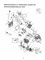
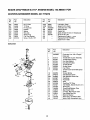
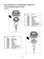
SEARS CRAFTSMAN 6,5 H.P. ENGINE MODEL 143.986501 FOR
CHIPPER-SHREDDER MODEL 247.775870
310 --
279
161A
307
I
305
\
161
308
159
4O
41
/
s
82
182
185 /
184 _ •
154
155
173
}--43
130A
_207 252
130
135
6
240
120
126
125
38 2
16
245
245A
/
900
119
250A
/
5
251
20
Page is loading ...
Page is loading ...
Page is loading ...
Page is loading ...
Page is loading ...
-
 1
1
-
 2
2
-
 3
3
-
 4
4
-
 5
5
-
 6
6
-
 7
7
-
 8
8
-
 9
9
-
 10
10
-
 11
11
-
 12
12
-
 13
13
-
 14
14
-
 15
15
-
 16
16
-
 17
17
-
 18
18
-
 19
19
-
 20
20
-
 21
21
-
 22
22
-
 23
23
-
 24
24
-
 25
25


Craftsman 247.775870 User manual
- Category
- Garden shredders
- Type
- User manual
Ask a question and I''ll find the answer in the document
Finding information in a document is now easier with AI
Related papers
-
Craftsman 247775890 User manual
-
-
-
-
-
-
-
-
-
Other documents
-
MTD Series 410 thru 420 User manual
-
Yard Machines 462 thru 465 User manual
-
Troy-Bilt 494 User manual
-
MTD 464 Series Owner's manual
-
-
Sears Chipper 247-795890 User manual
-
-
-
-
PowerSmart PS10 User manual