
A Division of Cisco Systems, Inc.
®
Model No.
WIRED
with 4-Port Switch
ADSL2 Gateway
AG241
User Guide

ADSL2 Gateway with 4-Port Switch
Copyright and Trademarks
Specifications are subject to change without notice. Linksys is a registered trademark or trademark of Cisco
Systems, Inc. and/or its affiliates in the U.S. and certain other countries. Copyright © 2004 Cisco Systems, Inc. All
rights reserved. Other brands and product names are trademarks or registered trademarks of their respective
holders.
How to Use this Guide
Your Guide to the ADSL2 Gateway with 4-Port Switch has been designed to make understanding networking with
the Gateway easier than ever. Look for the following items when reading this User Guide:
In addition to these symbols, there are definitions for technical terms that are presented like this:
Also, each figure (diagram, screenshot, or other image) is provided with a figure number and description, like
this:
Figure numbers and descriptions can also be found in the “List of Figures” section in the “Table of Contents”.
This exclamation point means there is a Caution or
Warning and is something that could damage your
property or the Gateway.
word: definition.
This checkmark means there is a Note of interest and
is something you should pay special attention to while
using the Gateway.
This question mark provides you with a reminder about
something you might need to do while using the Gateway.
Figure 0-1: Sample Figure Description
AG241-EU-UG-50208

ADSL2 Gateway with 4-Pot Switch
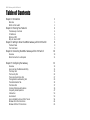
Table of Contents
Chapter 1: Introduction 1
Welcome 1
What’s in this Guide? 2
Chapter 2: Planning Your Network 4
The Gateway’s Functions 4
IP Addresses 4
What is a VPN? 5
Why do I need a VPN? 6
Chapter 3: Getting to Know the ADSL2 Gateway with 4-Port Switch 8
The Back Panel 8
The Front Panel 9
Chapter 4: Connecting the ADSL2 Gateway with 4-Port Switch 10
Overview 10
Wired Connection to a Computer 11
Chapter 5: Configuring the Gateway 13
Overview 13
How to Access the Web-based Utility 15
The Setup Tab 15
The Security Tab 22
The Access Restrictions Tab 27
The Applications and Gaming Tab 29
The Administration Tab 32
The Status Tab 37
Common Problems and Solutions 39
Frequently Asked Questions 47
Introduction 53
Environment 53
How to Establish a Secure IPSec Tunnel 54
Windows 98 or Me Instructions 64
Windows 2000 or XP Instructions 65

10/100 8-Port VPN Router
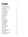
List of Figures
Figure 2-1: Network 4
Figure 2-2: Computer-to-VPN Gateway 6
Figure 2-3: VPN Gateway-to-VPN Gateway 7
Figure 3-1: Back Panel 8
Figure 3-2: Front Panel 9
Figure 4-1: Ethernet Connection 11
Figure 4-2: ADSL Connection 11
Figure 4-3: Power Connection 11
Figure 5-1: Password Screen 15
Figure 5-2: Basic Setup Tab 15
Figure 5-3: Dynamic IP 16
Figure 5-4: Static IP 16
Figure 5-5: IPoA 17
Figure 5-6: RFC 2516 PPPoE 17
Figure 5-7: RFC 2364 PPPoA 18
Figure 5-8: Bridged Mode Only 18
Figure 5-9: Optional Settings 19
Figure 5-10: DynDNS.org 20
Figure 5-11: TZO.com 20
Figure 5-12: Advanced Routing 21
Figure 5-13: Routing Table List 22
Figure 5-14: Firewall 23
Figure 5-15: VPN 24
Figure 5-16: VPN Settings Summary 24
Figure 5-17: Manual Key Management 25
Figure 5-18: System Log 25
Figure 5-19: Advanced VPN Tunnel Setup 26
Figure 5-20: Internet Access 27

10/100 8-Port VPN Router
Figure 5-21: Internet Policy Summary 27
Figure 5-22: List of PCs 28
Figure 5-23: Port Services 28
Figure 5-24: Single Port Forwarding 29
Figure 5-25: Port Range Forwarding 29
Figure 5-26: Port Triggering 30
Figure 5-27: DMZ 30
Figure 5-28: QOS 31
Figure 5-29: Management 32
Figure 5-30: Reporting 33
Figure 5-31: System Log 33
Figure 5-32: Ping Test 34
Figure 5-33: Backup&Restore 34
Figure 5-34: Factory Defaults 35
Figure 5-35: Firmware Upgrade 35
Figure 5-36: Reboot 36
Figure 5-37: Status 37
Figure 5-38: Local Network 37
Figure 5-39: DHCP Clients Table 37
Figure 5-40: DSL Connection 38
Figure B-1: Local Security Screen 54
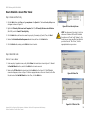
Figure B-2: Rules Tab 54
Figure B-3: IP Filter List Tab 54
Figure B-4: IP Filter LIst 55
Figure B-5: Filters Properties 55
Figure B-6: New Rule Properties 55
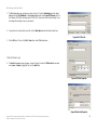
Figure B-7: IP Filter List 56
Figure B-8: Filters Properties 56
Figure B-9: New Rule Properties 56
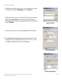
Figure B-10: IP Filter List Tab 57

10/100 8-Port VPN Router
Figure B-11: Filter Acton Tab 57
Figure B-12: Security Methods Tab 57
Figure B-13: Authentication Methods 58
Figure B-14: Preshared Key 58
Figure B-15: New Preshared Key 58
Figure B-16: Tunnel Setting Tab 59
Figure B-17: Connection Type Tab 59
Figure B-18: Properties Screen 59
Figure B-19: IP Filter List Tab 60
Figure B-20: Filter Action Tab 60
Figure B-21: Authentication Methods Tab 60
Figure B-22: Preshared Key 61
Figure B-23: New Preshared Key 61
Figure B-24: Tunnel Setting Tab 61
Figure B-25: Connection Type 62
Figure B-26: Rules 62
Figure B-27: Local Computer 62
Figure B-28: VPN Tab 63
Figure C-1: IP Configuration Screen 64
Figure C-2: MAC Address/Adapter Address 64
Figure C-3: MAC Address/Physical Address 65
Figure D-1: Upgrade Firmware 66

1
Chapter 1: Introduction
Welcome
ADSL2 Gateway with 4-Port Switch
Chapter 1: Introduction
Welcome
The Linksys ADSL2 Gateway with 4-Port Switch is the all-in-one solution for Internet connectivity in your home.
The ADSL Modem function gives you a blazing fast connection to the Internet, far faster than a dial-up, and
without tying up your phone line.
Connect your computers to the Gateway via the built-in 4-port 10/100 Ethernet Switch to jump start your home
network. You can share files, printers, hard drive space and other resources, or play head-to-head computer
games. Attach four computers directly, or connect more hubs and switches to create as big a network as you
need. The Gateway ties it all together and lets your whole network share that high-speed Internet connection.
To protect your data and privacy, the ADSL2 Gateway with 4-Port Switch features an advanced firewall to keep
Internet intruders and attackers out.
Safeguard your family with Parental Control features like Internet Access Time Limits and Key Word Blocking.
Configuration is a snap with any web browser.
With the Linksys ADSL2 Gateway with 4-Port Switch at the heart of your home network, you're connected to the
future.

2
Chapter 1: Introduction
What’s in this Guide?
ADSL2 Gateway with 4-Port Switch
What’s in this Guide?
This user guide covers the steps for setting up and using the ADSL2 Gateway with 4-Port Switch.
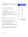
• Chapter 1: Introduction
This chapter describes the ADSL2 Gateway with 4-Port Switch ADSL2 Gateway with 4-Port Switch
applications and this User Guide.
• Chapter 2: Planning Your Network
This chapter describes the basics of networking.
• Chapter 3: Getting to Know the ADSL2 Gateway with 4-Port Switch
This chapter describes the physical features of the Gateway.
• Chapter 4: Connecting the ADSL2 Gateway with 4-Port Switch
This chapter instructs you on how to connect the Gateway to your network.
• Chapter 5: Configuring the Gateway
This chapter explains how to use the Web-Based Utility to configure the settings on the Gateway.
• Appendix A: Troubleshooting
This appendix describes some problems and solutions, as well as frequently asked questions, regarding
installation and use of the ADSL2 Gateway with 4-Port Switch.
• Appendix B: Configuring IPSec between a Windows 2000 Computer and the Gateway
This appendix instructs you on how to establish a secure IPSec tunnel using preshared keys to join a private
network inside the VPN Gateway and a Windows 2000 or XP computer.
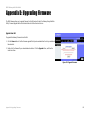
• Appendix C: Upgrading Firmware
This appendix instructs you on how to upgrade the firmware on your Gateway if you should need to do so.
• Appendix D: Finding the MAC Address and IP Address for your Ethernet Adapter.
This appendix describes how to find the MAC address for your computer’s Ethernet adapter so you can use
the MAC filtering and/or MAC address cloning feature of the Gateway.
• Appendix E: Glossary
This appendix gives a brief glossary of terms frequently used in networking.
• Appendix F: Specifications
This appendix provides the technical specifications for the Gateway.

3
Chapter 1: Introduction
What’s in this Guide?
ADSL2 Gateway with 4-Port Switch
• Appendix G: Warranty Information
This appendix supplies the warranty information for the Gateway.
• Appendix H: Regulatory Information
This appendix supplies the regulatory information regarding the Gateway.
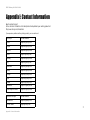
• Appendix I: Contact Information
This appendix provides contact information for a variety of Linksys resources, including Technical Support.

4
Chapter 2: Planning Your Network
The Gateway’s Functions
ADSL2 Gateway with 4-Port Switch
Chapter 2: Planning Your Network
The Gateway’s Functions
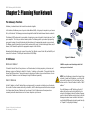
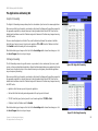
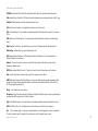
A Gateway is a network device that connects two networks together.
In this instance, the Gateway connects your Local Area Network (LAN), or the group of computers in your home or
office, to the Internet. The Gateway processes and regulates the data that travels between these two networks.
The Gateway’s NAT feature protects your network of computers so users on the public, Internet side cannot “see”
your computers. This is how your network remains private. The Gateway protects your network by inspecting
every packet coming in through the Internet port before delivery to the appropriate computer on your network.
The Gateway inspects Internet port services like the web server, ftp server, or other Internet applications, and, if
allowed, it will forward the packet to the appropriate computer on the LAN side.
Remember that the Gateway’s ports connect to two sides. The LAN ports connect to the LAN, and the ADSL port
connects to the Internet. The LAN ports transmit data at 10/100Mbps.
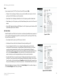
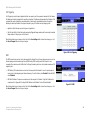
IP Addresses
What’s an IP Address?
IP stands for Internet Protocol. Every device on an IP-based network, including computers, print servers, and
Gateways, requires an IP address to identify its “location,” or address, on the network. This applies to both the
Internet and LAN connections. There are two ways of assigning an IP address to your network devices. You can
assign static IP addresses or use the Gateway to assign IP addresses dynamically.
Static IP Addresses
A static IP address is a fixed IP address that you assign manually to a computer or other device on the network.
Since a static IP address remains valid until you disable it, static IP addressing ensures that the device assigned
it will always have that same IP address until you change it. Static IP addresses must be unique and are
commonly used with network devices such as server computers or print servers.
LAN: the computers and networking products that
make up your local network
NOTE: Since the Gateway is a device that connects two
networks, it needs two IP addresses—one for the LAN,
and one for the Internet. In this User Guide, you’ll see
references to the “Internet IP address” and the “LAN IP
address.”
Since the Gateway uses NAT technology, the only IP
address that can be seen from the Internet for your
network is the Gateway’s Internet IP address. However,
even this Internet IP address can be blocked, so that the
Gateway and network seem invisible to the Internet—
see the Block WAN Requests description under Security
in “Chapter 5: Configuring the Gateway.”
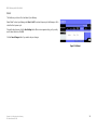
Figure 2-1: Network

5
Chapter 2: Planning Your Network
What is a VPN?
ADSL2 Gateway with 4-Port Switch
Since you use the Gateway to share your DSL Internet connection, contact your ISP to find out if they have
assigned a static IP address to your account. If so, you will need that static IP address when configuring the
Gateway. You can get that information from your ISP.
Dynamic IP Addresses
A dynamic IP address is automatically assigned to a device on the network, such as computers and print servers.
These IP addresses are called “dynamic” because they are only temporarily assigned to the computer or device.
After a certain time period, they expire and may change. If a computer logs onto the network (or the Internet) and
its dynamic IP address has expired, the DHCP server will automatically assign it a new dynamic IP address.
DHCP (Dynamic Host Configuration Protocol) Servers
Computers and other network devices using dynamic IP addressing are assigned a new IP address by a DHCP
server. The computer or network device obtaining an IP address is called the DHCP client. DHCP frees you from
having to assign IP addresses manually every time a new user is added to your network.
A DHCP server can either be a designated computer on the network or another network device, such as the
Gateway. By default, the Gateway’s DHCP Server function is enabled.
If you already have a DHCP server running on your network, you must disable one of the two DHCP servers. If you
run more than one DHCP server on your network, you will experience network errors, such as conflicting IP
addresses. To disable DHCP on the Gateway, see the DHCP section in “Chapter 5: Configuring the Gateway.”
What is a VPN?
A VPN, or Virtual Private Network, is a connection between two endpoints - a VPN Gateway, for instance - in
different networks that allows private data to be sent securely over a shared or public network, such as the
Internet. This establishes a private network that can send data securely between these two locations or
networks.
This is done by creating a “tunnel”. A VPN tunnel connects the two computers or networks and allows data to be
transmitted over the Internet as if it were still within those networks. Not a literal tunnel, it is a connection
secured by encrypting the data sent between the two networks.
VPN was created as a cost-effective alternative to using a private, dedicated, leased line for a private network.
Using industry standard encryption and authentication techniques - IPSec, short for IP Security - the VPN creates
a secure connection that, in effect, operates as if you were directly connected to your local network. Virtual
Private Networking can be used to create secure networks linking a central office with branch offices,

6
Chapter 2: Planning Your Network
Why do I need a VPN?
ADSL2 Gateway with 4-Port Switch
telecommuters, and/or professionals on the road (travelers can connect to a VPN Gateway using any computer
with VPN client software that supports IPSec, such as SSH Sentinel.)
There are two basic ways to create a VPN connection:
• VPN Gateway to VPN Gateway
• Computer (using VPN client software that supports IPSec) to VPN Gateway
The VPN Gateway creates a “tunnel” or channel between two endpoints, so that data transmissions between
them are secure. A computer with VPN client software that supports IPSec can be one of the two endpoints. Any
computer with the built-in IPSec Security Manager (Microsoft 2000 and XP) allows the VPN Gateway to create a
VPN tunnel using IPSec (refer to “Appendix C: Configuring IPSec between a Windows 2000 or XP computer and
the VPN Gateway”). Other versions of Microsoft operating systems require additional, third-party VPN client
software applications that support IPSec to be installed.
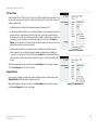
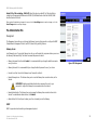
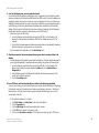
Computer (using VPN client software that supports IPSec) to VPN Gateway
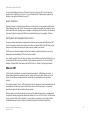
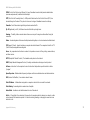
The following is an example of a computer-to-VPN Gateway VPN. (See Figure 2-2.) In her hotel room, a traveling
businesswoman dials up her ISP. Her notebook computer has VPN client software that is configured with her
office's VPN settings. She accesses the VPN client software that supports IPSec and connects to the VPN Gate-
way at the central office. As VPNs utilize the Internet, distance is not a factor. Using the VPN, the businesswoman
now has a secure connection to the central office's network, as if she were physically connected.
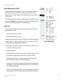
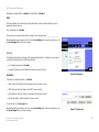
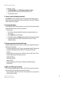
VPN Gateway to VPN Gateway
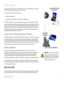
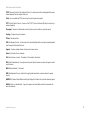
An example of a VPN Gateway-to-VPN Gateway VPN would be as follows. (See Figure 2-3.) At home, a
telecommuter uses his VPN Gateway for his always-on Internet connection. His Gateway is configured with his
office's VPN settings. When he connects to his office's Gateway, the two Gateways create a VPN tunnel,
encrypting and decrypting data. As VPNs utilize the Internet, distance is not a factor. Using the VPN, the
telecommuter now has a secure connection to the central office's network, as if he were physically connected.
For additional information and instructions about creating your own VPN, please visit Linksys’s international
website at www.linksys.com/international or refer to “Appendix C: Configuring IPSec between a Windows 2000 or
XP computer and the VPN Gateway.”
Why do I need a VPN?
Computer networking provides a flexibility not available when using a paper-based system. With this flexibility,
however, comes an increased risk in security. This is why firewalls were first introduced. Firewalls help to
IMPORTANT: You must have at least one VPN
Gateway on one end of the VPN tunnel. At the
other end of the VPN tunnel, you must have a
second VPN Gateway or a computer with VPN
client software that supports IPSec.
Figure 2-2: Computer-to-VPN Gateway

7
Chapter 2: Planning Your Network
Why do I need a VPN?
ADSL2 Gateway with 4-Port Switch
protect data inside of a local network. But what do you do once information is sent outside of your local network,
when emails are sent to their destination, or when you have to connect to your company's network when you are
out on the road? How is your data protected?
That is when a VPN can help. VPNs secure data moving outside of your network as if it were still within that
network.
When data is sent out across the Internet from your computer, it is always open to attacks. You may already have
a firewall, which will help protect data moving around or held within your network from being corrupted or
intercepted by entities outside of your network, but once data moves outside of your network - when you send
data to someone via email or communicate with an individual over the Internet - the firewall will no longer protect
that data.
At this point, your data becomes open to hackers using a variety of methods to steal not only the data you are
transmitting but also your network login and security data. Some of the most common methods are as follows:
1) MAC Address Spoofing
Packets transmitted over a network, either your local network or the Internet, are preceded by a packet header.
These packet headers contain both the source and destination information for that packet to transmit efficiently.
A hacker can use this information to spoof (or fake) a MAC address allowed on the network. With this spoofed
MAC address, the hacker can also intercept information meant for another user.
2) Data Sniffing
Data “sniffing” is a method used by hackers to obtain network data as it travels through unsecured networks,
such as the Internet. Tools for just this kind of activity, such as protocol analyzers and network diagnostic tools,
are often built into operating systems and allow the data to be viewed in clear text.
3) Man in the Middle Attacks
Once the hacker has either sniffed or spoofed enough information, he can now perform a “man in the middle”
attack. This attack is performed, when data is being transmitted from one network to another, by rerouting the
data to a new destination. Even though the data is not received by its intended recipient, it appears that way to
the person sending the data.
These are only a few of the methods hackers use and they are always developing more. Without the security of
your VPN, your data is constantly open to such attacks as it travels over the Internet. Data travelling over the
Internet will often pass through many different servers around the world before reaching its final destination.
That's a long way to go for unsecured data and this is when a VPN serves its purpose.
Figure 2-3: VPN Gateway-to-VPN Gateway

8
Chapter 3: Getting to Know the ADSL2 Gateway with 4-Port Switch
The Back Panel
ADSL2 Gateway with 4-Port Switch
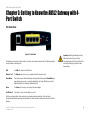
Chapter 3: Getting to Know the ADSL2 Gateway with 4-
Port Switch
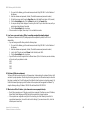
The Back Panel
The Gateway’s ports, where a network cable is connected, are located on the back panel. The Gateway’s buttons
are also located on the back panel.
LINE The LINE port connects to the ADSL line.
Ethernet (1-4) The Ethernet ports connect to your computer and other network devices.
Reset Button There are two ways to Reset the Gateway's factory defaults. Either press the Reset Button, for
approximately ten seconds, or restore the defaults from the Factory Defaults screen of the
Administration tab in the Gateway’s Web-Based Utility.
Power The Power port is where you will connect the power adapter.
On/Off Switch This switch is used to turn the Gateway on or off.
With these, and many other, Linksys products, your networking options are limitless. Go to the Linksys
international website at www.linksys.com/international for more information about products that work with the
Gateway.
Important: Resetting the Gateway to factory
defaults will erase all of your settings
and replace them with the factory defaults. Do
not reset the Gateway if you want to retain
these settings.
Figure 3-1: Back Panel

9
Chapter 3: Getting to Know the ADSL2 Gateway with 4-Port Switch
The Front Panel
ADSL2 Gateway with 4-Port Switch
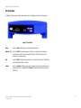
The Front Panel
The Gateway's LEDs, where information about network activity is displayed, are located on the front panel.
Power Green. The Power LED lights up when the Gateway is powered on.
Ethernet (1-4) Green. The LAN LED serves two purposes. If the LED is continuously lit, the Gateway is
successfully connected to a device through the LAN port. If the LED is blinking, it is an
indication of any network activity.
DSL Green. The DSL LED lights up whenever there is a successful DSL connection. The LED blinks
while establishing the ADSL connection.
Internet Green. The Internet LED lights up green when an Internet connection to the Internet Service
Provider (ISP) session is established. The Internet LED lights up red when the connection to
the ISP fails.
Figure 3-2: Front Panel

10
Chapter 4: Connecting the ADSL2 Gateway with 4-Port Switch
Overview
ADSL2 Gateway with 4-Port Switch
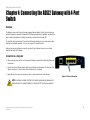
Chapter 4: Connecting the ADSL2 Gateway with 4-Port
Switch
Overview
The Gateway’s setup consists of more than simply plugging hardware together. You will have to configure your
networked computers to accept the IP addresses that the Gateway assigns them (if applicable), and you will also
have to configure the Gateway with setting(s) provided by your Internet Service Provider (ISP).
The installation technician from your ISP should have left the setup information for your modem with you after
installing your broadband connection. If not, you can call your ISP to request that data.
After you have the setup information you need for your specific type of Internet connection, you can begin
installation and setup of the Gateway.
Connection to a Computer
1. Before you begin, make sure that all of your network’s hardware is powered off, including the Gateway and
all computers.
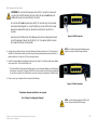
2. Connect one end of an Ethernet network cable to one of the Ethernet ports (labeled 1-4) on the back of the
Gateway (see Figure 4-1), and the other end to an Ethernet port on a computer.
3. Repeat this step to connect more computers, a switch, or other network devices to the Gateway.
Figure 4-1: Ethernet Connection
NOTE:
A small device called a microfilter (not included) may be necessary between each
phone and wall jack to prevent interference. Contact your ISP if you have any questions.

11
Chapter 4: Connecting the ADSL2 Gateway with 4-Port Switch
Connection to a Computer
ADSL2 Gateway with 4-Port Switch
4. Connect a phone cable from the Line port on the Gateway’s back panel (see Figure 4-2) to the wall jack of
the ADSL line. A small device called a microfilter may be necessary between each phone and wall jack to
prevent interference. Contact your ISP if you have any questions.
5. Connect the power adapter to the Gateway’s Power port (see Figure 4-3), and then plug the power adapter
into a power outlet. Turn the On/Off switch to On.
• The Power LED on the front panel will light up green as soon as the power adapter is connected properly
and the switch is turned on. The Power LED will flash for a few seconds, then it will light up steady when
the self-test is complete. If the LED flashes for one minute or longer, see “Appendix A: Troubleshooting.”
6. Power on one of your computers that is connected to the Gateway.
The Gateway’s hardware installation is now complete.
Go to “Chapter 5: Configuring the Gateway.”
Figure 4-2: ADSL Connection
Figure 4-3: Power Connection
NOTE: You should always plug the Gateway’s power
adapter into a power strip with surge protection.
NOTE: You should always change the SSID from its
default, linksys, and enable WEP encryption.
IMPORTANT: For countries that have phone jacks with RJ-11 connectors, make sure to
only place the microfilters between the phone and the wall jack and not between the
Modem and the wall jack or your ADSL will not connect.
For countries that do not have phone jacks with RJ-11 connectors (e.g. France, Sweden,
Switzerland, United Kingdom, etc.), except for ISDN users, the microfilter has to be used
between the modem and the wall jack, because the microfilter will have the RJ-11
connector.
Annex B users (E1 and DE versions of the Gateway) must use the included special cable to
connect the gateway to the wall jack (RJ-45 to RJ-12). If you require splitters or special
jacks, please contact your service provider.

13
Chapter 5: Configuring the Gateway
Overview
ADSL2 Gateway with 4-Port Switch
Chapter 5: Configuring the Gateway
Overview
Follow the steps in this chapter and use the Gateway’s web-based utility to configure the Gateway. This chapter
will describe each web page in the Utility and each page’s key functions. The utility can be accessed via your web
browser through use of a computer connected to the Gateway. For a basic network setup, most users only have to
use the following screens of the Utility:
• Basic Setup. On the Basic Setup screen, enter the settings provided by your ISP.
• Management. Click the Administration tab and then the Management tab. The Gateway’s default username
and password is admin. To secure the Gateway, change the Password from its default.
There are six main tabs: Setup, Security, Access Restrictions, Applications & Gaming, Administration, and Status.
Additional tabs will be available after you click one of the main tabs.
Setup
• Basic Setup. Enter the Internet connection and network settings on this screen.
• DDNS. To enable the Gateway’s Dynamic Domain Name System (DDNS) feature, complete the fields on this
screen.
• Advanced Routing. On this screen, you can alter Dynamic Routing, and Static Routing configurations.
Security
• Firewall. This screen contains Filters and Block WAN Requests. Filters block specific internal users from
accessing the Internet and block anonymous Internet requests.
• VPN. To enable or disable IPSec and/or PPTP Pass-through, and set up VPN tunnels, use this screen.
Access Restrictions
• Internet Access. This screen allows you to prevent or permit only certain users from attaching to your
network.
Note: For added security, you should change
the password through the Administration tab.
Have You: Enabled TCP/IP on your computers?
computers communicate over the network with
this protocol. Refer to Windows Help for more
information on TCP/IP.

14
Chapter 5: Configuring the Gateway
Overview
ADSL2 Gateway with 4-Port Switch
Applications & Gaming
• Single Port Forwarding. Use this screen to set up common services or applications on your network.
• Port Range Forwarding. To set up public services or other specialized Internet applications on your network,
click this tab.
• Port Triggering. To set up triggered ranges and forwarded ranges for Internet applications, click this tab.
• DMZ. To allow one local user to be exposed to the Internet for use of special-purpose services, use this
screen.
• QoS. QoS ensures better service to high-priority types of network traffic, which may involve demanding, real-
time applications, such as Internet phone calls or videoconferencing.
Administration
• Management. On this screen, alter Gateway access privileges, SNMP, UPnP, and WT-82 settings.
• Reporting. If you want to view or save activity logs, click this tab.
• Diagnostics. Use this screen to do a Ping Test.
• Backup&Restore. The Backup&Restore tab allows you to back up and restore the Gateway’s configuration file.
• Factory Defaults. If you want to restore the Gateway’s factory defaults, use this screen.
• Firmware Upgrade. Click this tab if you want to upgrade the Gateway’s firmware.
• Reboot. This tab allows you to do a soft or hard reboot of your Gateway.
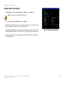
Status
• Gateway. This screen provides status information about the Gateway.
• Local Network. This provides status information about the local network.
• DSL Connection. This screen provides status information about the DSL connection.

15
Chapter 5: Configuring the Gateway
How to Access the Web-based Utility
ADSL2 Gateway with 4-Port Switch
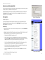
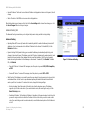
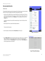
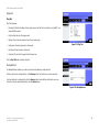
How to Access the Web-based Utility
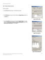
To access the web-based utility, launch Internet Explorer or Netscape Navigator, and enter the Gateway’s default
IP address, 192.168.1.1, in the Address field. Then press Enter.
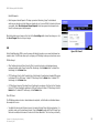
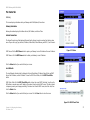
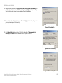
A password request page, shown in Figure 5-1 will appear. (non-Windows XP users will see a similar screen.)
Enter admin (the default user name) in the User Name field, and enter admin (the default password) in the
Password field. Then click the OK button.
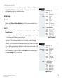
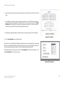
The Setup Tab
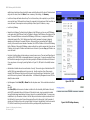
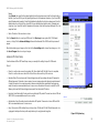
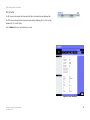
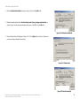
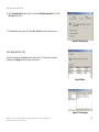
The Basic Setup Tab
The first screen that appears is the Basic Setup tab. This tab allows you to change the Gateway's general
settings. Change these settings as described here and click the Save Settings button to save your changes or
Cancel Changes to cancel your changes.
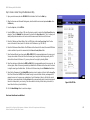
Internet Setup
• PVC Connection. Select a PVC connection number from the drop-down menu. Then, select the Enable Now to
enable the connection.
• VC Settings. Virtual Circuits (VPI and VCI): These fields consist of two items: VPI (Virtual Path Identifier) and VCI
(Virtual Channel Identifier). Your ISP will provide the correct settings for these fields.
• Multiplexing: Select LLC or VC , depending on your ISP.
• QOS Type: Select from the drop-down menu: CBR, Continuous Bit Rate to specify fixed bandwidth for
voice or data traffic; UBR, Unspecific Bit Rate for application that are none-time sensitive, such as email;
or VBR, Variable Bite Rate for Bursty traffic and bandwidth sharing with other application.
• Pcr Rate: Peak Cell Rate, divide the DSL line rate by 424 to find the PCR to get the maximum rate the
sender can send cells. Enter the rate in the field (if required by your service provider).
• Scr Rate: Sustain Cell Rate, sets the average cell rate that can be transmitted. SCR normally less than
PCR. Enter the rate in the field (if required by your service provider).
• Autodetect: Select Enable to have the settings automatically entered or Disable to enter the values
manually.
• Virtual Circuit: Enter the VPI and VCi ranges in the fields.
Figure 5-2: Basic Setup Tab
Figure 5-1: Password Screen
Page is loading ...
Page is loading ...
Page is loading ...
Page is loading ...
Page is loading ...
Page is loading ...
Page is loading ...
Page is loading ...
Page is loading ...
Page is loading ...
Page is loading ...
Page is loading ...
Page is loading ...
Page is loading ...
Page is loading ...
Page is loading ...
Page is loading ...
Page is loading ...
Page is loading ...
Page is loading ...
Page is loading ...
Page is loading ...
Page is loading ...
Page is loading ...
Page is loading ...
Page is loading ...
Page is loading ...
Page is loading ...
Page is loading ...
Page is loading ...
Page is loading ...
Page is loading ...
Page is loading ...
Page is loading ...
Page is loading ...
Page is loading ...
Page is loading ...
Page is loading ...
Page is loading ...
Page is loading ...
Page is loading ...
Page is loading ...
Page is loading ...
Page is loading ...
Page is loading ...
Page is loading ...
Page is loading ...
Page is loading ...
Page is loading ...
Page is loading ...
Page is loading ...
Page is loading ...
Page is loading ...
Page is loading ...
Page is loading ...
Page is loading ...
Page is loading ...
Page is loading ...
Page is loading ...
Page is loading ...
-
 1
1
-
 2
2
-
 3
3
-
 4
4
-
 5
5
-
 6
6
-
 7
7
-
 8
8
-
 9
9
-
 10
10
-
 11
11
-
 12
12
-
 13
13
-
 14
14
-
 15
15
-
 16
16
-
 17
17
-
 18
18
-
 19
19
-
 20
20
-
 21
21
-
 22
22
-
 23
23
-
 24
24
-
 25
25
-
 26
26
-
 27
27
-
 28
28
-
 29
29
-
 30
30
-
 31
31
-
 32
32
-
 33
33
-
 34
34
-
 35
35
-
 36
36
-
 37
37
-
 38
38
-
 39
39
-
 40
40
-
 41
41
-
 42
42
-
 43
43
-
 44
44
-
 45
45
-
 46
46
-
 47
47
-
 48
48
-
 49
49
-
 50
50
-
 51
51
-
 52
52
-
 53
53
-
 54
54
-
 55
55
-
 56
56
-
 57
57
-
 58
58
-
 59
59
-
 60
60
-
 61
61
-
 62
62
-
 63
63
-
 64
64
-
 65
65
-
 66
66
-
 67
67
-
 68
68
-
 69
69
-
 70
70
-
 71
71
-
 72
72
-
 73
73
-
 74
74
-
 75
75
-
 76
76
-
 77
77
-
 78
78
-
 79
79
-
 80
80


Ask a question and I''ll find the answer in the document
Finding information in a document is now easier with AI
Related papers
Other documents
-
Linksys ADSL2+ User manual
-
Linksys WAG354G (EU) User manual
-
Linksys WAG54G User manual
-
-
-
Linksys WAG54GP2 User manual
-
Linksys WAG200G Owner's manual
-
AOpen 4-Port 10/100Mbps Ethernet Broadband Router User manual
-
-
Cisco Systems WRV54G User manual