Metos Falcon E3913i 400 Owner's manual
- Category
- Hobs
- Type
- Owner's manual
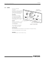
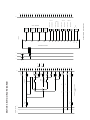
Metos Falcon E3913i 400 is a high-powered induction range with a glass-ceramic cooktop and a convection oven. The four individually controlled cooking zones provide 5kW of power each, allowing you to cook food quickly and efficiently. The oven has a 6.4kW twin-fan convection system and five shelf positions, providing ample space and even cooking.
The induction hob requires the use of proper pan type for correct operation. Suitable pans are those made with ferrous materials, such as stainless steel or steel. The induction hob also features a number of safety features, including:
- Automatic pan detection: The hob will only operate when a pan is placed on the cooking zone.


-
 1
1
-
 2
2
-
 3
3
-
 4
4
-
 5
5
-
 6
6
-
 7
7
-
 8
8
-
 9
9
-
 10
10
-
 11
11
-
 12
12
-
 13
13
-
 14
14
-
 15
15
-
 16
16
-
 17
17
-
 18
18


Metos Falcon E3913i 400 Owner's manual
- Category
- Hobs
- Type
- Owner's manual
Metos Falcon E3913i 400 is a high-powered induction range with a glass-ceramic cooktop and a convection oven. The four individually controlled cooking zones provide 5kW of power each, allowing you to cook food quickly and efficiently. The oven has a 6.4kW twin-fan convection system and five shelf positions, providing ample space and even cooking.
The induction hob requires the use of proper pan type for correct operation. Suitable pans are those made with ferrous materials, such as stainless steel or steel. The induction hob also features a number of safety features, including:
- Automatic pan detection: The hob will only operate when a pan is placed on the cooking zone.
Ask a question and I''ll find the answer in the document
Finding information in a document is now easier with AI
Related papers
-
Metos Ardox IE4 Owner's manual
-
-
-
-
-
-
-
-
-
Other documents
-
Bartscher 296318 Operating instructions
-
Falcon E3441R (GP101) Owner's manual
-
-
FlowerHouse FHXUPT-GT Installation guide
-
Sirman IH27 Induction Cooker User manual
-
-
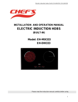 Chef's EH-DIH333 Operating instructions
-
Transmitter NOTOUCHREX Owner's manual
-
-
