Weslo WLTL62790 User manual

Category
Treadmills
Type
User manual

This manual is also suitable for

USER'S MANUAL
¨
CAUTION
Read all precautions and instruc-
tions in this manual before using
this equipment. Save this manual
for future reference.
Serial
Number
Decal
Model No. WLTL62790
Serial No.
Find the serial number in the location
shown below. Write the serial number
in the space above for reference.
Visit our website at
www.weslo.com
new products, prizes,
fitness tips, and much more!
QUESTIONS?
As a manufacturer, we are com-
mitted to providing complete
customer satisfaction. If you
have questions, or if there are
missing parts, we will guarantee
complete satisfaction through di-
rect assistance from our factory.
TO AVOID UNNECESSARY DE-
LAYS, PLEASE CALL DIRECT TO
OUR TOLL-FREE CUSTOMER
HOT LINE. The trained techni-
cians on our Customer Hot Line
will provide immediate assis-
tance, free of charge to you.
CUSTOMER HOT LINE:
1-800-999-3756
Mon.ÐFri., 6 a.m.Ð6 p.m. MST
2
TABLE OF CONTENTS
IMPORTANT PRECAUTIONS . . . . . . . . . . . . . . . . . . . . . . . . . . . . . . . . . . . . . . . . . . . . . . . . . . . . . . . . . . . . . . . . .3
BEFORE YOU BEGIN . . . . . . . . . . . . . . . . . . . . . . . . . . . . . . . . . . . . . . . . . . . . . . . . . . . . . . . . . . . . . . . . . . . . . . .6
ASSEMBLY . . . . . . . . . . . . . . . . . . . . . . . . . . . . . . . . . . . . . . . . . . . . . . . . . . . . . . . . . . . . . . . . . . . . . . . . . . . . . . .7
TREADMILL OPERATION . . . . . . . . . . . . . . . . . . . . . . . . . . . . . . . . . . . . . . . . . . . . . . . . . . . . . . . . . . . . . . . . . . . .9
TELEVISION OPERATION . . . . . . . . . . . . . . . . . . . . . . . . . . . . . . . . . . . . . . . . . . . . . . . . . . . . . . . . . . . . . . . . . .12
HOW TO FOLD AND MOVE THE TREADMILL . . . . . . . . . . . . . . . . . . . . . . . . . . . . . . . . . . . . . . . . . . . . . . . . . .18
TROUBLE-SHOOTING . . . . . . . . . . . . . . . . . . . . . . . . . . . . . . . . . . . . . . . . . . . . . . . . . . . . . . . . . . . . . . . . . . . . .19
CONDITIONING GUIDELINES . . . . . . . . . . . . . . . . . . . . . . . . . . . . . . . . . . . . . . . . . . . . . . . . . . . . . . . . . . . . . . .22
PART LIST . . . . . . . . . . . . . . . . . . . . . . . . . . . . . . . . . . . . . . . . . . . . . . . . . . . . . . . . . . . . . . . . . . . . . . . . . . . . . . .23
ORDERING REPLACEMENT PARTS . . . . . . . . . . . . . . . . . . . . . . . . . . . . . . . . . . . . . . . . . . . . . . . . . .Back Cover
LIMITED WARRANTY . . . . . . . . . . . . . . . . . . . . . . . . . . . . . . . . . . . . . . . . . . . . . . . . . . . . . . . . . . . . . . .Back Cover
Note: An EXPLODED DRAWING is attached in the center of this manual.
¨
WARNING: Before beginning this or any exercise program, consult your physician. This
is especially important for persons over the age of 35 or persons with pre-existing health problems.
Read all instructions before using. ICON assumes no responsibility for personal injury or property
damage sustained by or through the use of this product.
3
1. It is the responsibility of the owner to ensure
that all users of this treadmill are adequately
informed of all warnings and precautions.
2. Use the treadmill only as described in this
manual.
3. The treadmill is intended for home use only.
Do not use the treadmill in a commercial,
rental, or institutional setting.
4. Place the treadmill on a level surface, with
eight feet of clearance behind it. To protect
the floor or carpet from damage, place a mat
under the treadmill.
5. Slots and openings in the treadmill and TV
are provided for ventilation, to ensure reliable
operation, and to help prevent overheating.
These openings must not be blocked or cov-
ered. Do not place the treadmill on any sur-
face that blocks openings or near a radiator
or other heat source.
6. Keep the treadmill indoors, away from mois-
ture and dust. Do not place the treadmill in a
garage or covered patio or near water.
7. Do not operate the treadmill where aerosol
products are used or where oxygen is being
administered.
8. You must be able to safely lift 45 pounds (20
kg) in order to raise or lower the treadmill.
9. Keep children under the age of 12 and pets
away from the treadmill at all times.
10. The treadmill should not be used by persons
weighing more than 250 pounds.
11. Never allow more than one person on the
treadmill at a time.
12. Wear appropriate exercise clothing when
using the treadmill. Do not wear loose cloth-
ing that could become caught in the tread-
mill. Athletic support clothes are recom-
mended for both men and women.
13. Always wear athletic shoes when using the
treadmill. Never use the treadmill with bare
feet, wearing only stockings, or in sandals.
14. Inspect and tighten all parts of the treadmill
regularly.
15. The treadmill operates on 120 V, 60 Hz, AC
power only. Consult your dealer before con-
necting the treadmill if you do not know the
AC voltage in your area, as incorrect voltage
might damage the treadmill or TV. Never con-
nect the treadmill to other than the specified
voltage such as 50 Hz or to direct current.
16. When connecting the power cord (see HOW
TO PLUG IN THE POWER CORD on page 9),
plug the power cord into a surge protector
(not included) and plug the surge protector
into a grounded circuit capable of carrying 15
or more amps. No other appliance should be
on the same circuit. Do not overload the wall
outlets as this can result in a risk of electric
shock, fires, and other hazards.
17. Use only a UL-listed surge protector, rated at
15 amps, with a 14-gauge cord of five feet or
less in length. Do not use an extension cord.
18. The power cord and the surge protector
should be positioned so they are not likely to
be walked on or pinched by items placed
upon or against them; pay particular atten-
tion to the cords at the plugs, the conve-
nience receptacles, and the point where the
power cord exits the treadmill. Keep the
power cord and the surge protector away
from heated surfaces.
19. Do not operate the treadmill if the power cord
or plug is damaged or if the treadmill is not
working properly.
20. If an outside antenna or cable system is con-
nected, be sure that the antenna or cable sys-
tem is grounded so as to provide some pro-
tection against voltage surges and built-up
static charges. Section 810 of the National
Electrical Code, ANSI/NFPA No. 70-1984,
WARNING: To reduce the risk of burns, fire, electric shock, or injury to persons, read the
following important precautions and information before operating the treadmill.
IMPORTANT PRECAUTIONS
4
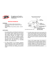
provides information with respect to proper
grounding of the mast and supporting struc-
ture, grounding of the lead-in wire to an an-
tenna discharge unit, size of grounding con-
ductors, location of antenna discharge unit,
connection to grounding electrodes, and re-
quirements for the grounding electrode.
21. An outside antenna system should not be lo-
cated in the vicinity of overhead power lines
or other electric light or power circuits, or
where it can fall into such power lines or cir-
cuits. When installing an outside antenna
system, extreme care should be taken to
keep from touching such power lines or cir-
cuits as contact with them might be fatal.
22. Never start the treadmill while you are stand-
ing on the walking belt. Always hold the
handrails while using the treadmill.
23. The treadmill is capable of high speeds.
Adjust the speed in small increments to
avoid sudden jumps in speed.
24. Never leave the treadmill unattended while it
is running. Move the on/off switch to the ÒoffÓ
position when the treadmill is not in use.
25. To protect the treadmill and TV during light-
ning storms, unplug the power cord from the
wall outlet and disconnect the antenna or
cable system. This will prevent damage due
to lightning and power line surges.
26. Never drop or insert any object into any
opening.
27. DANGER: Always unplug the power
cord immediately after use, before cleaning
the treadmill, and before performing the
maintenance and adjustment procedures de-
scribed in this manual. Never remove the
motor hood unless instructed to do so by an
authorized service representative. Servicing
other than the procedures in this manual
should be performed by an authorized ser-
vice representative only.
28. To reduce the risk of electric shock, do not
remove the cover or back of the TV. There are
no user serviceable parts inside. Refer ser-
vicing to qualified service personnel.
29. The graphic symbols on the back cover of the
TV mean the following:
The lightning flash with arrowhead
symbol within an equilateral trian-
gle is intended to alert the user to
the presence of uninsulated Òdan-
gerous voltageÓ within the TVÕs enclosure
that may be of sufficient magnitude to consti-
tute a risk of electric shock to persons.
The exclamation point within an
equilateral triangle is intended to
alert the user to the presence of im-
portant operating and maintenance
(servicing) instructions in this manual.
30. Unplug the treadmill from the wall outlet and
refer servicing to qualified service personnel
under the following conditions:
¥ When the power cord or plug is damaged
¥ If liquid has been spilled, or objects have
fallen into the treadmill
¥ If the treadmill has been exposed to water
¥ If the treadmill or TV does not operate nor-
mally when the operating instructions are
followed. Adjust only those controls that
are covered by the operating instructions,
as improper adjustment of other controls
may result in damage and will often require
extensive work by a qualified technician to
restore normal operation
¥ If the treadmill has been dropped
¥ When the treadmill exhibits a distinct
change in performance.
31. When replacement parts are required, be
sure the service technician uses replacement
parts specified by the manufacturer or those
that have the same characteristics as the
original part. Unauthorized substitutions may
result in fire, electric shock, or other hazards.
32. Upon completion of any service or repairs to
the treadmill or TV, ask the service technician
to perform safety checks to determine that
5
the unit is in proper operating condition
(refer to the drawing below).
¥ Use No. 10 AWG (5.3mm
2
) copper, No. 8
AWG (8.4mm
2
) aluminum, No. 17 AWG
(1.0mm
2
) copper-clad steel or bronze wire,
or larger as a ground wire.
¥ Secure antenna lead-in and ground wires to
house with stand-off insulators spaced
from 4 to 6 feet (1.22 to 1.83m) apart.
¥ Mount antenna discharge unit as close as
possible to where the lead-in enters the
house.
¥ Use jumper wire not smaller than No. 6
AWG (13.3mm
2
) copper, or the equivalent
when a separate antenna-grounding elec-
trode is used. See NEC Section 810-21 (j).
Note to CATV system installer: This reminder is
provided to call the CATV system installerÕs at-
tention to Article 820-40 of the NEC that provides
guidelines for proper grounding and, in particu-
lar, specifies that the cable ground shall be con-
nected to the grounding system of the building,
as close to the point of cable entry as practical.
Power Lines
Ground
Clamps
Ground
Clamps
Ground
Clamp
Bonding
Jumper
Standoff
Insulators
Antenna
Lead-in Wire
Ground Wire
Ground
Wire
Antenna
Discharge Unit
To External Antenna
Terminal of Treadmill
Mast
Service
Entrance
Equipment
Power Service Grounding
Electrode System (e.g.
Interior Metal Water Pipe)
Service
Entrance
Conductors
Optional Antenna Grounding Electrode Driven 8
Feet (2.44m) Into The Earth (If Required By Local
Codes). See NEC Section 810Ð21 (f).
SAVE THESE INSTRUCTIONS
The decal shown below has been placed on your treadmill in
the indicated location. If the decal is missing or illegible,
please call our Customer Service Department, toll-free, at
1-800-999-3756 to order a free replacement decal. Apply the
decal in the location shown.
Note: The decal is shown at 38% of actual size.
6
Thank you for selecting the new WESLO
¨
CADENCE
TV36 treadmill. The CADENCE TV36 treadmill com-
bines advanced technology with innovative design to
help you get the most from your exercise program in
the convenience of your home. And when youÕre not
exercising, the unique CADENCE TV36 can be folded
up, requiring less than half the floor space of other
treadmills.
For your benefit, read this manual carefully before
using the treadmill. If you have additional questions,
please call our Customer Service Department toll-free
at 1-800-999-3756, Monday through Friday, 6 a.m.
until 6 p.m. Mountain Time (excluding holidays). To
help us assist you, please note the product model
number and serial number before calling. The model
number of the treadmill is WLTL62790. The serial
number can be found on a decal attached to the tread-
mill (see the front cover of this manual for the location).
Before reading further, please familiarize yourself with
the parts that are labeled in the drawing below.
BEFORE YOU BEGIN
Handrail
Console
Storage Latch
Television
Key/Clip
Circuit
Breaker
On/Off Switch
Walking Belt
Cushioned Walking Platform
Front
Wheel
Foot Rail
Power Cord
Rear Roller
Adjustment Bolts
Water Bottle
Holder (Bottle
not included)
RIGHT SIDELEFT SIDE
7
ASSEMBLY
Assembly requires two people. Set the treadmill in a cleared area and remove all packing materials. Do not
dispose of the packing materials until assembly is completed. Assembly requires the included allen wrench
and your own phillips screwdriver .
Note: The underside of the treadmill walking belt is coated with high-performance lubricant. During shipping, a
small amount of lubricant may be transferred to the top of the walking belt or the shipping carton. This is a normal
condition and does not affect treadmill performance. If there is lubricant on top of the walking belt, simply wipe off
the lubricant with a soft cloth and a mild, non-abrasive cleaner.
1. With the help of a second person, carefully raise the
Uprights (61) until the treadmill is in the position shown.
Identify the Right Extension Leg (101) by looking at the
sticker on the underside. Insert the Right Extension Leg
into the right side of the treadmill as shown. (Note: It may
be helpful to tip the Uprights (61) in the direction shown
by the arrow as you insert the Extension Leg.) Attach the
Extension Leg with a Long Extension Leg Screw (18).
Make sure to push on the head of the Extension Leg
Screw while tightening it.
Attach the Left Extension Leg (not shown) in the same way.
2. Insert the upper end of a Handrail (53) into the right
Upright (61) as shown. Note: It will be necessary to
pivot the Handrail to the side and back repeatedly
(see arrow A) while pushing on the Handrail (see
arrow B) to insert it fully into the Upright. Next, pivot
the lower end of the Handrail down and push it against
the bracket on the Right Extension Leg.
Insert the other Handrail (53) into the left Upright (61) in
the same way.
101
Bracket
18
61
1
Bracket
61
61
53
53
2
B
A
3. Make sure that the hole in the Handrail (53) is aligned with
the hole in the bracket on the Extension Leg (101). If the
holes are not aligned, rotate the Handrail away from the
treadmill and slide the upper end of the Handrail out of the
Upright (61) slightly. Then, rotate the lower end of the
Handrail back to the position shown by the dotted line in
drawing 2. Repeat, if necessary, until the holes are
aligned. Make sure that the lower end of the Handrail is
against the bracket on the Extension Leg. Using the in-
cluded allen wrench, tighten a Handrail Screw (77) into
the bracket and the Handrail.
Attach the other Handrail (not shown) in the same way.
53
101
77
61
3
8
7. Make sure that all parts are tightened before you use
the treadmill. Note: The ratchet screws on the adjustable
rear incline are factory set and should not be adjusted.
Keep the included allen wrench in a secure place. The
allen wrench is used to adjust the walking belt (see page
20). To protect the floor or carpet from damage, place a
mat under the treadmill.
4. Remove the Lock Knob (54) from the Lock Pin (59).
Press the Lock Knob Sleeve (55) into the left Upright (61).
Make sure that the Lock Pin Collar (57) and the Spring
(56) are on the Lock Pin. Insert the Lock Pin into the left
Upright (61) and tighten the Lock Knob onto the Lock Pin.
59
61
56
57
55
54
4
5. Note the location of the 75 ohm antenna terminal on
the treadmill (for clarity, the treadmill is shown in the
storage position). For the television to operate prop-
erly, an antenna, a CATV cable, or a VCR must be con-
nected to the 75 ohm antenna terminal.
If you are using an antenna, it must be properly con-
nected and adjusted for optimal reception. Refer to AN-
TENNA CONNECTIONS on pages 12 and 13 to properly
connect an antenna.
If you are using a CATV cable, refer to CATV CABLE
CONNECTION on page 13 to properly connect the cable.
If you are using a VCR, refer to HOW TO CONNECT A
VCR on page 17 to properly connect the VCR. The VCR
must be turned on, a videocassette must be properly
inserted, and the VCR must be playing. Refer to your
VCR userÕs manual for operating instructions.
6. The console requires two "AA" batteries (not included).
Alkaline batteries are recommended. To install batteries,
first open the Battery Cover (98) as shown. Press two
batteries into the battery compartment, with the negative
ends of the batteries (marked ÒÐÓ) touching the springs.
Close the battery cover, push up on the battery cover tab,
and then push the tab forward as shown. Be sure that the
tab locks into place.
5
6
Ratchet
Screws
Batteries
98
75 Ohm
Antenna
Terminal
Battery
Cover Tab
7
9
THE PERFORMANT LUBE
TM
WALKING BELT
Your treadmill features a walking belt coated with
PERFORMANT LUBE
TM
, a high-performance lubricant.
IMPORTANT: Never apply silicone spray or other
substances to the walking belt or the walking plat-
form. They will deteriorate the walking belt and
cause excessive wear.
HOW TO PLUG IN THE POWER CORD
Your treadmill, like any other type of sophisticated
electronic equipment, can be seriously damaged by
sudden voltage changes in your homeÕs power.
Voltage surges, spikes, and noise interference can re-
sult from weather conditions or from other appliances
being turned on or off.
To decrease the pos-
sibility of your tread-
mill being damaged,
always use a surge
protector (not in-
cluded) with your
treadmill.
Surge protectors are
sold at most hardware
stores and department
stores. Use only a UL-
listed surge protector,
rated at 15 amps, with a
14-gauge cord of five
feet or less in length.
This product must be
grounded. If it should
malfunction or break
down, grounding pro-
vides a path of least re-
sistance for electric cur-
rent to reduce the risk of
electric shock. This product is equipped with a cord
having an equipment-grounding conductor and a
grounding plug. Plug the power cord into a surge
protector, and plug the surge protector into an ap-
propriate outlet that is properly installed and
grounded in accordance with all local codes and
ordinances.
This product is for use on a nominal 120-volt circuit,
and has a grounding plug that looks like the plug illus-
trated in drawing 1 below. A temporary adapter that
looks like the adapter illustrated in drawing 2 may be
used to connect the surge protector to a 2-pole recep-
tacle as shown in drawing 2 if a properly grounded out-
let is not available.
The temporary adapter should be used only until a
properly grounded outlet (drawing 1) can be installed
by a qualified electrician.
The green-colored rigid ear, lug, or the like extending
from the adapter must be connected to a permanent
ground such as a properly grounded outlet box cover.
Whenever the adapter is used it must be held in place
by a metal screw. Some 2-pole receptacle outlet box
covers are not grounded. Contact a qualified elec-
trician to determine if the outlet box cover is
grounded before using an adapter.
DANGER: Improper connection
of the equipment-grounding conductor can
result in an increased risk of electric shock.
Check with a qualified electrician or service-
man if you are in doubt as to whether the
product is properly grounded. Do not modify
the plug provided with the productÑif it will
not fit the outlet, have a proper outlet in-
stalled by a qualified electrician.
1
2
Grounded Outlet Box
Grounded Outlet Box
Grounding Plug
Treadmill Power Cord
Grounding Plug
Grounding Plug
Grounding Pin
Surge Protector
Grounding Pin
Grounding Pin
Adapter
Lug
Metal Screw
Grounded Outlet
10
CONSOLE DIAGRAM
FEATURES OF THE CONSOLE
The treadmill console is designed to make your work-
outs more enjoyable and effective. As you exercise,
the integral color TV will show your favorite television
programs while the LCD displays show the elapsed
time, the distance you have walked, the approximate
numbers of calories and fat calories you have burned,
and the speed of the walking belt.
To operate the treadmill, follow the instructions at the
right.
To operate the color TV, follow the instructions begin-
ning on page 12. IMPORTANT: For the television to
operate properly, an antenna, a CATV cable, or a
VCR must be connected to the 75 ohm antenna
terminal on the treadmill.
If you are using an antenna, it must be properly con-
nected and adjusted. Refer to ANTENNA CONNEC-
TIONS on pages 12 and 13 to properly connect an an-
tenna.
If you are using a CATV cable, refer to CATV CABLE
CONNECTION on page 13 to connect the cable.
If you are using a VCR, refer to HOW TO CONNECT
A VCR on page 17 to properly connect the VCR.
STEP-BY-STEP CONSOLE OPERATION
Note: The console requires two ÒAAÓ batteries (not in-
cluded). If you have not installed batteries, see assem-
bly step 6 on page 8.
Locate the on/off
switch near the power
cord. Make sure that
the on/off switch is in
the on position. In addi-
tion, make sure that
the power cord is prop-
erly plugged in (see
HOW TO PLUG IN THE POWER CORD on page 9).
When you are ready to
begin exercising, step
onto the foot rails of
the treadmill. Find the
clip attached to the
key, and slide the clip
onto the waistband of
your clothing.
Follow the steps on page 11 to operate the console.
CAUTION: Before operating the
console, read the following precautions.
¥ Do not stand on the walking belt when turn-
ing on the power or starting the walking belt.
¥ Always wear the clip (see the drawing
above) while using the treadmill. When the
key is pulled from the console, the walking
belt will stop.
¥ The treadmill is capable of high speeds.
Adjust the speed in small increments.
¥ Never leave the treadmill unattended while
it is running.
¥ To reduce the possibility of electric shock,
keep the console dry. Avoid spilling liquids
on the console and use only a sealable
water bottle.
Note: If there is a thin sheet of clear plastic
on the face of the console, remove it before
operating the console.
Clip
11
Insert the key into the console.
Inserting the key
will not turn on the
displays. The dis-
plays will turn on
when the ON/
RESET button is
pressed or when
the walking belt is
started. Note: If you just installed batteries, the
displays will already be on.
Reset the speed control.
Slide the speed
control to the
RESET position.
Note: Each time
the walking belt is
stopped, the
speed control
must be moved to
the RESET position before the walking belt
can be restarted.
Start the walking belt.
After you have
moved the speed
control to the
RESET position,
slowly slide it to the
right until the walk-
ing belt begins to
move at slow
speed. Carefully step onto the walking belt and
begin exercising. Change the speed of the walking
belt as desired by sliding the speed control.
To stop the walking belt, step onto the foot rails
and slide the speed control to the RESET position.
Monitor your progress with the LCD displays.
TIME/DISTANCE dis-
playÑThis display
shows the elapsed time
and distance that you
have walked or run, in
miles. Every seven sec-
onds, the display will change from one number to
the other. Arrows in the display will show which
number is currently shown.
CALS/FAT CALS/
SPEED displayÑThis
display shows the ap-
proximate numbers of
calories and fat calories
you have burned. (See
FAT BURNING on page 22.) In addition, the dis-
play shows the speed of the walking belt, in miles
per hour. Every seven seconds, the display will
change. Arrows in the display will indicate which
information is currently shown.
To reset the displays at
any time, press the
ON/RESET button.
When you are finished exercising, stop the
walking belt and remove the key.
Step onto the foot rails, stop the walking belt, and
remove the key from the console. The displays will
turn off about five minutes after the key is re-
moved. Note: Any time that the walking belt is
stopped and the ON/RESET button is not
pressed for five minutes, the displays will au-
tomatically turn off in order to conserve the
batteries.
HOW TO CHANGE THE INCLINE OF THE TREADMILL
The incline of the treadmill can be changed by raising
or lowering the back end. Before changing the in-
cline, remove the key and unplug the power cord.
Hold the
rear roller
endcap with
both hands.
When the
back end of
the treadmill
is in the low-
est position,
the incline is
about 10%.
Raise the back end until it clicks into position. (Note: It
may be necessary to shake the treadmill lightly so that
it clicks into position.) The incline will then be about
7%. Raise the back end again until it clicks into posi-
tion. The incline will then be about 3%. To lower the
back end, raise it past the highest position and then
lower it. CAUTION: Before exercising, push on the
back of the treadmill to make sure that the incline
legs are locked in position. Do not place objects
under the treadmill to change the incline; change
the incline only as described above.
5
4
3
2
1
Incline
Leg
Hold the Rear
Roller Endcap
in these locations
12
1. Power indicator (Note: The power indicator will
remain on whenever the on/off switch is on.)
2. POWER button
3. CHANNEL
and
buttons
4. VOLUME + and Ð buttons
5. Compartment door (IMPORTANT: The treadmill
and TV, like any other electronic equipment,
can be damaged by static electricity. Before
touching the controls behind the compartment
door, touch one of the treadmill handrails to
discharge static electricity.)
6. TV/CATV button
7. TV/AV button
8. Pop-up MENU button
9. Earphone Jack
¥ Blackstripe picture tube
¥ 181 cable-ready channels (68 standard TV channels
and 113 cable channels)
¥ Full-featured on-screen display
¥ User-friendly menu-driven TV controls
¥ Video and audio input jacks
¥ Real time clock with one on-timer and one off-timer
¥ Mono audio
¥ Earphone jack
¥ LED power indicator
¥ Auto memory and auto search for TV channel
¥ Automatically skips unavailable channels in your area
Note: If desired, the TV can be viewed without the
treadmill being used. Make sure that the on/off switch
located near the power cord is in the ÒonÓ position.
(See the drawing near the top of page 10.)
Indoor Antenna
1. Place the VHF
antenna in the
desired loca-
tion. Connect
the 300 ohm
flat wire to the
screws on the
300 ohm to 75
ohm adapter.
2. Connect the
300 to 75 ohm
adapter to the
75 ohm antenna
terminal on the
treadmill. (See
assembly draw-
ing 5 on page 8
to find the loca-
tion of the termi-
nal.)
TELEVISION OPERATION
FEATURES OF THE TELEVISIONDIAGRAM OF THE TELEVISION
1
2 4
5
3
6
7 8
9
ANTENNA CONNECTIONS
300 to 75 Ohm Adapter
Screwdriver
VHF 300
Ohm Flat
Wire
75 Ohm
Terminal
300 to 75 Ohm
Adapter
VHF Rod
Antenna
13
Outdoor Antenna
Outdoor antennas are subject to weathering that can
reduce signal quality. Inspect the antenna and lead-in
wiring before connecting the antenna. Any service cen-
ter can explain the various outdoor antennas available.
300 Ohm Flat Wire
1. Refer to the drawing above. Connect the 300 ohm
flat wire to the 300 ohm to 75 ohm adapter.
2. Push the end of the 300 ohm to 75 ohm adapter
into the 75 ohm antenna terminal on the treadmill.
(See assembly drawing 5 on page 8 to find the lo-
cation of the terminal.)
75 Ohm Coaxial Cable
Refer to the drawing above. Connect the 75 ohm coax-
ial cable directly to the 75 ohm antenna terminal. (See
assembly drawing 5 on page 8 to find the location of
the terminal.)
1. Remove the VHF 300 to 75 ohm adapter or the VHF
cable from the antenna terminal. (See assembly draw-
ing 5 on page 8 to find the location of the terminal.)
2. Connect the CATV
cable (75 ohm coaxial
cable) to the 75 ohm
antenna terminal on
the treadmill.
Read the important
precautions on pages
3 to 5 of this manual.
Before operating the TV,
make sure that the
on/off switch located
near the power cord is
in the ÒonÓ position. In
addition, make sure that the power cord is properly
plugged in (see page 9).
Turning on the Power
To turn on the TV, press the POWER button on the TV.
Volume Control
To adjust the volume to the desired level, press the
VOLUME + or Ð button.
The sound level will be
shown by a bar on the TV
screen. As the sound level is
increased, the bar will move
to the right. As the sound
level is decreased, the bar
will move to the left. Note: If
no broadcasting signal is re-
ceived, the sound will be muted and the volume control
will be disabled.
Skip Mode
Press the CHANNEL
or
button to select memo-
rized channels, skipping over empty channels. Hold
down the CHANNEL
or
button to change channels
continuously. Note: If no channels are memorized, the
TV will switch to the SEARCH mode.
Search Mode
Press the CHANNEL
or
button to search for the
next available channel. Hold down the CHANNEL
or
button to search through all available channels.
Note: Before selecting channels with the CHANNEL
or
button, the channels must be set into the TVÕs
memory. See MEMORIZING CHANNELS on page 14.
Combination
VHF/UHF Antennas
300 Ohm
Flat Wire
75 Ohm
Terminal
on Treadmill
300 to 75
Ohm Adapter
75 Ohm
Coaxial Cable
75 Ohm CATV Cable
VHF 75 Ohm Jack
75 Ohm CATV Cable
CATV CABLE CONNECTION
BASIC TV OPERATION
VOLUME
14
Memorizing Channels
The TV is equipped with a channel memorizing func-
tion that allows you to step up or down from the current
channel to the next channel set into memory. Before
channels can be selected in this way, they must be set
into the TVÕs memory. Note: When programming
channels, if no buttons are pressed for four sec-
onds, the TV will return to the normal screen.
Automatic Memory Tuning
1. Press the MENU button
to turn on the pop-up
menu in the TV mode or
CATV mode. Press the
MENU button again to
select CH MEMORY
(channel memory).
2. Press the MENU button
again to select AUTO
MEMORY.
3. Press the + button to
start AUTO MEMORY.
The TV will begin setting
into memory all the chan-
nels available in your
area. When no broadcast
signal is detected on a
channel, the channel is
erased from memory. When a signal is detected, the
channel is stored in memory and the next channel is
selected.
This process will be re-
peated until the highest
channel is reached. It then
stops at the lowest channel
stored in memory, and re-
turns to a normal screen
after four seconds. The TV
will then be in the SKIP
mode.
Erasing Channels
After all channels available in your area have been set
into memory, you can erase unwanted channels by fol-
lowing the steps below:
1. Select the unwanted channel by using the CHANNEL
and
button.
2. Press the MENU button
to turn on the pop-up
menu. Press the MENU
button again to select CH
MEMORY.
3. Press the + or Ð button to
move the arrow to MEM-
ORY ADD¥ERASE.
Select MEMORY
ADD¥ERASE by pressing
the MENU button.
4. Press the Ð button to
erase the stored channel
from memory. The chan-
nel number will change
from green to red.
Adding Channels
Channels that are not in memory can be stored manu-
ally. To manually store a channel, follow the steps
above, but press the + button when MEMORY ADD¥
ERASE is selected. The channel will be stored in
memory, and the channel number will change from red
to green.
CHANNEL PROGRAMMING
CH MEMORY
ANALOG
CLOCK/TIMER
TV 07
AUTO MEMORY
START [+]
TV 07
AUTO MEMORY
END
AUTO MEMORY
SEARCH/SKIP
MEMORY ADD
¥ERASE
TV/CATV
CH MEMORY
ANALOG
CLOCK/TIMER
AUTO MEMORY
SEARCH/SKIP
MEMORY ADD
¥ERASE
TV/CATV
TV 07
CHANNEL MEMORY
END ERASE
[ + ] [ Ð ]
15
Manually Searching for and Storing Channels
1. Press the MENU button
to turn on the pop-up
menu. Press the MENU
button again to select
CH MEMORY.
2. Press the + or Ð button
to move the arrow to
SEARCH/SKIP. Select
SEARCH/SKIP by press-
ing the MENU button.
3. Press the Ð button to se-
lect the SEARCH mode.
The TV will return to the
normal screen after four
seconds.
4. Press the CHANNEL
or
button to start search-
ing. It will stop whenever an available channel is
found.
5. If you do not want to store the channel in memory,
press the CHANNEL
or
button again. To store
the channel in memory, refer to ADDING CHAN-
NELS at the left.
6. Until all desired channels have been stored, return
to SEARCH/SKIP as described above and press the
+ button to return to the SKIP mode.
In addition to normal broadcast reception, the TV is
equipped to receive up to 125 cable channels (113 and
12 TV channels). To use the TV with a cable TV sys-
tem, following the steps below.
1. Press the MENU button
to turn on the pop up
menu. Press the MENU
button again to select CH
MEMORY.
2. Press the + or Ð button to
move the arrow to
TV/CATV. Select
TV/CATV by pressing the
MENU button.
3. Press the MENU button
to cycle through the four
channel modes: (1) TV;
(2) STD (Standard) for
cable TV mode; (3) HRC
(Harmonic Related
Carrier) for cable TV sub-
scriber; (4) IRC (Incre-
mental Related Carrier) for cable TV subscriber.
Once the appropriate cable TV mode is selected, the
screen will return to normal after two seconds. Note:
Consult your cable company if you are not sure which
system you are using, or try different systems to obtain
the maximum number of channels.
To toggle between the TV mode and the cable TV
mode, press the TV/CATV button on the TV.
To memorize cable TV channels, refer to CHANNEL
PROGRAMMING on page 14.
CATV Channel Reference Table
Use the table below to find which CATV channel your
TV is displaying. The top row (in bold) represents the
channel number shown on the TV screen; the bottom
row represents the corresponding CATV channel.
CHANNEL UP/DOWN
SKIP : [ + ]
SEARCH : [ Ð ]
CH MEMORY
ANALOG
CLOCK/TIMER
AUTO MEMORY
SEARCH/SKIP
MEMORY ADD
¥ERASE
TV/CATV
CABLE TV (CATV) OPERATION
TV 07
CH MEMORY
ANALOG
CLOCK/TIMER
AUTO MEMORY
SEARCH/SKIP
MEMORY ADD
¥ERASE
TV/CATV
1, 2 . . . . 6 . . . . 13, 14 . . . . 26 . . . . 36, 37 . . . . 50 . . . . 65,
5A, 2 . . . . 6 . . . . 13, A . . . . M . . . . W, W+1 . . W+14 . .W+29,
66 . . . . 75 . . . . 86 . . . . 94, 95 . . . . 99, 100 . . . . 112 . . . . 125
W+30 . . W+39 . . W+50 . . W+58, A-5 . . A-1, W+59 . . W+71 . . W+84
16
Picture level controls are preset to nominal levels. If
desired, you can individually adjust the contrast, bright-
ness, color, or tint by following the steps below.
1. Press the MENU button
to turn on the pop-up
menu.
2. Press the + or Ð button
to move the arrow to
ANALOG.
3. Press the MENU button
to select CONTRAST,
BRIGHTNESS, COLOR,
or TINT.
4. Press the + or Ð button to adjust the level.
Press the TV/AV button on the TV to toggle between
TV and VIDEO input.
Your TV has the capability to turn on, switch to a chan-
nel for recording, and then turn off againÑall automati-
cally. Follow the instructions below to use this feature.
Note: When setting the clock, the on timer, or the
off timer, if no buttons are pressed for four sec-
onds, the TV will return to the normal screen.
Setting the Clock
1. Press the MENU button
to turn on the pop-up
menu.
2. Press the + or Ð button to
move the arrow to
CLOCK/TIMER.
3. Press the MENU button
to turn on the setting
menu.
2. Press the + or Ð button to set the clock to the correct
time.
Setting the On Timer
1. After the clock has been
set, press the MENU but-
ton to select ON TIME.
2. Press the + or Ð button to set the time that you want
the TV to turn on.
CLOCK AM 12:00
ON TIME
AM 12:00 OFF
ON CH 02 TV
OFF TIME
AM 12:00 OFF
CLOCK AM 12:00
ON TIME
AM 12:00 OFF
ON CH 02 TV
OFF TIME
AM 12:00 OFF
PICTURE LEVEL ADJUSTMENTS
SELECTING VIDEO INPUT
CONTRAST
CH MEMORY
ANALOG
CLOCK/TIMER
CH MEMORY
ANALOG
CLOCK/TIMER
CH MEMORY
ANALOG
CLOCK/TIMER
CH MEMORY
ANALOG
CLOCK/TIMER
USING THE RECORDING TIMER
Setting the Channel to be Recorded
1. After the on timer has
been set, press the
MENU button repeatedly
to select ON CH (on
channel).
2. Press the + button to cycle through the channels
until the desired channel is selected.
3. Press the Ð button to cycle through the four channel
modes: (1) TV, (2) STD, (3) HRC, (4) IRC.
After the channel has been set, press the MENU but-
ton to select the on/off setting mode of the on timer.
Pressing the + or Ð button at this point will change the
display to ÒON,Ó reset the seconds of the on timer, and
start the count.
Setting the Off Timer
1. After a channel has been
set, press the MENU
button repeatedly to se-
lect OFF TIME.
2. Press the + or Ð button to set the time that you want
the TV to turn off.
After the channel has been set, pressing the MENU
button will select the on/off setting mode of the off
timer. Pressing the + or Ð button at this point will
change the display to ÒON,Ó reset the seconds of the
off timer, and start the count.
When the menu is used, pressing the MENU button
will display a menu that allows selection of channel
memory, the clock, the on timer, the off timer, or pic-
ture level controls. When the MENU button is pressed,
the display will be as shown below.
TV Mode Video Mode
Follow the steps below to connect your VCR (not in-
cluded) to the treadmill. A CATV cable (75 ohm coaxial
cable) at least nine feet long is required.
1. Connect one end of the CATV cable to the video
output jack on the VCR.
2. Plug in the power cord of the VCR. Refer to your
VCR userÕs manual for proper grounding instructions.
3. Connect the CATV cable to the 75 ohm antenna ter-
minal on the treadmill. (See assembly drawing 5 on
page 8 to find the location of the terminal.
To operate the VCR
with the TV, make sure
that the on/off switch lo-
cated near the power
cord is in the ÒonÓ posi-
tion, and that the power
cord is properly plugged
in (see page 9).
To turn on the TV, press the POWER button on the TV.
Make sure that the TV is on channel 3 or 4. Note: When
the treadmill is not in use, you may want to leave the
surge protector plugged in. Each time the power cord is
unplugged, the TV must go through an automatic chan-
nel resetting routine when the power is turned on again.
17
CLOCK AM 12:00
ON TIME
AM 12:00 OFF
ON CH 02 TV
OFF TIME
AM 12:00 OFF
CLOCK AM 12:00
ON TIME
AM 12:00 OFF
ON CH 02 TV
OFF TIME
AM 12:00 OFF
HOW TO CONNECT A VCR
USING THE MENU FUNCTION
CH MEMORY
ANALOG
CLOCK/TIMER
ANALOG
CLOCK/TIMER
HOW TO FOLD AND MOVE THE TREADMILL
HOW TO FOLD THE TREADMILL FOR STORAGE
Before folding the treadmill, adjust the incline to the
lowest position. If this is not done, the treadmill may be
permanently damaged. Next, unplug the power cord.
CAUTION: You must be able to safely lift 45 pounds (20
kg) in order to raise, lower, or move the treadmill.
1. Hold the treadmill with your hands in the locations shown
at the right. CAUTION: To decrease the possibility of in-
jury, bend your legs and keep your back straight. As
you raise the treadmill, make sure to lift with your legs
rather than your back. Raise the treadmill about halfway
to the vertical position.
2. Move your right hand to the position shown and hold the
treadmill firmly. Hold the lock knob with your left hand and
pull it to the left. Position the treadmill until the hole in the
side of the treadmill lines up with the lock pin. Slowly re-
lease the lock knob. Make sure that the pin on the lock
knob is fully insert into the hole in the frame.
To protect the floor or carpet from damage, place a
mat under the treadmill. Keep the treadmill out of
direct sunlight. Do not leave the treadmill in the stor-
age position in temperatures above 85¡ Fahrenheit.
HOW TO MOVE THE TREADMILL
Before moving the treadmill, convert the treadmill to the stor-
age position as described above. Make sure that the pin
on the lock knob is holding the treadmill frame securely.
1. Hold the handrails as shown and place one foot against a
wheel.
2. Tilt the treadmill back until it rolls freely on the front wheels.
Carefully move the treadmill to the desired location. Never
move the treadmill without tipping it back. To reduce
the risk of injury, use extreme caution while moving
the treadmill. Do not attempt to move the treadmill
over an uneven surface.
3. Place one foot on the base, and carefully lower the
treadmill until it is resting in the storage position.
HOW TO LOWER THE TREADMILL FOR USE
1. Refer to drawing 2 above. Hold the upper end of the treadmill with your right hand as shown. Using your left
hand, pull the lock knob to the left and hold it. Pivot the treadmill down until the frame is past the pin on the lock
know.
2. Refer to drawing 1 above. Hold the treadmill firmly with both hands, and lower the treadmill to the floor.
CAUTION: To decrease the possibility of injury, bend your legs and keep your back straight.
Base
Front Wheels
1
Knob
Hole
2
18
TROUBLE-SHOOTING
Most treadmill problems can be solved by following the steps below. Find the symptom that applies, and
follow the steps listed. If further assistance is needed, please call our Customer Service Department toll-
free at 1-800-999-3756, Monday through Friday, 6 a.m. until 6 p.m. Mountain Time (excluding holidays).
PROBLEM: The power does not turn on
SOLUTION: a. Make sure that the power cord is plugged into a surge protector, and that the surge protector is
plugged into a properly grounded outlet. (See HOW TO PLUG IN THE POWER CORD on page
9.) Use only a UL-listed surge protector, rated at 15 amps, with a 14-gauge cord of five feet or
less in length.
b. After the power cord has been plugged in, make sure that the key is fully inserted into the console.
c. Check the circuit breaker located on the treadmill
near the power cord. If the switch protrudes as
shown, the circuit breaker has tripped. To reset the
circuit breaker, wait for five minutes and then press
the switch back in.
d. Check the on/off switch located on the treadmill
near the power cord. The switch must be in the on
position.
PROBLEM: The power turns off during use
SOLUTION: a. Check the circuit breaker located on the treadmill frame near the power cord (see c. above). If the
circuit breaker has tripped, wait for five minutes and then press the switch back in.
b. Make sure that the power cord is plugged in.
c. Remove the key from the console. Reinsert the key fully into the console.
d. Make sure that the on/off switch is in the on position.
e. If the treadmill still will not run, please call our Customer Service Department, toll-free.
PROBLEM: The displays of the console do not function properly
SOLUTION: a. Check the batteries in the console. See assembly step 6 on page 8. Most problems are the result
of drained batteries.
a. Remove the key from the console and unplug the
power cord. Remove the screws from the hood and
carefully remove the hood. Locate the Reed Switch (9)
and the Magnet (8) on the left side of the Pulley (12).
Turn the Pulley until the Magnet is aligned with the
Reed Switch. Make sure that the gap between the
Magnet and the Reed Switch is about 1/8Ó. If nec-
essary, loosen the Screw (39) and move the Reed
Switch slightly. Retighten the Screw. Re-attach the
hood, and run the treadmill for a few minutes to check
for a correct speed reading.
Tripped
Reset
Tripped
c
Reset
On
Position
d
8
9
89
Top
View
12
1/8Ó
19
PROBLEM: The walking belt slows when walked on
SOLUTION: a. Use only a UL-listed surge protector, rated at 15 amps, with a 14-gauge cord of five feet or less in
length.
b. If the walking belt is overtightened, treadmill perfor-
mance may decrease and the walking belt may be-
come damaged. Remove the key and UNPLUG THE
POWER CORD. Using the allen wrench, turn both
rear roller adjustment bolts counterclockwise, 1/4 of a
turn. When the walking belt is properly tightened, you
should be able to lift each side of the walking belt 2 to
3 inches off the walking platform. Be careful to keep
the walking belt centered. Plug in the power cord, in-
sert the key and run the treadmill for a few minutes.
Repeat until the walking belt is properly tightened.
c. If the walking belt still slows, please call our Customer Service Department, toll-free.
PROBLEM: The walking belt is off-center
SOLUTION: a. If the walking belt has shifted to the left, first remove
the key and UNPLUG THE POWER CORD. Using the
allen wrench, turn the left rear roller adjustment bolt
clockwise, and the right bolt counterclockwise, 1/4 of a
turn each. Be careful not to overtighten the walking belt.
Plug in the power cord, insert the key and run the tread-
mill for a few minutes. Repeat until the walking belt is
centered.
b. If the walking belt has shifted to the right, first re-
move the key and UNPLUG THE POWER CORD.
Using the allen wrench, turn the left rear roller adjust-
ment bolt counterclockwise, and the right bolt clockwise,
1/4 of a turn each. Be careful not to overtighten the
walking belt. Plug in the power cord, insert the key and
run the treadmill for a few minutes. Repeat until the
walking belt is centered.
PROBLEM: The walking belt slips when walked on
SOLUTION: a. If the walking belt slips when walked on, first remove
the key and UNPLUG THE POWER CORD. Using the
allen wrench, turn both rear roller adjustment bolts
clockwise, 1/4 of a turn. When the walking belt is cor-
rectly tightened, you should be able to lift each side of
the walking belt 2 to 3 inches off the walking platform.
Be careful to keep the walking belt centered. Plug in the
power cord, insert the key and carefully walk on the
treadmill for a few minutes. Repeat until the walking belt
is properly tightened.
Rear Roller Adjustment Bolts
2ÓÐ3Ó
b
b
a
a
20
  • Page 1 1
  • Page 2 2
  • Page 3 3
  • Page 4 4
  • Page 5 5
  • Page 6 6
  • Page 7 7
  • Page 8 8
  • Page 9 9
  • Page 10 10
  • Page 11 11
  • Page 12 12
  • Page 13 13
  • Page 14 14
  • Page 15 15
  • Page 16 16
  • Page 17 17
  • Page 18 18
  • Page 19 19
  • Page 20 20
  • Page 21 21
  • Page 22 22
  • Page 23 23
  • Page 24 24
  • Page 25 25
  • Page 26 26

Weslo WLTL62790 User manual

Category
Treadmills
Type
User manual
This manual is also suitable for

Ask a question and I''ll find the answer in the document

Finding information in a document is now easier with AI