American Power Conversion AP9222 User manual
- Category
- Power distribution units (PDUs)
- Type
- User manual
This manual is also suitable for

MasterSwitch VM
Power Distribution Unit
AP9222
AP9222EXP
User’s Guide

Thank You!
Thank you for selecting the
APC
MasterSwitch
VM
(vertical-mount)
power distribution unit (
PDU
). It has been designed for many years of
reliable, maintenance-free service.
APC
is dedicated to the
development of high-performance electrical power conversion and
control products. We hope that you will find this product a valuable,
convenient addition to your system.
Please read this manual!
It provides important configuration and
operating instructions that will help you get the most from your
MasterSwitch
VM power distribution unit. See the
Installation and Quick
Start Manual
includedwithMasterSwitch
VM
andonthis
CD
for more
detailed information on installing and setting up the unit.

MasterSwitch VM
MasterSwitch VM User’s Guide iii
Contents
Introduction.................................
1
ProductDescription .............................1
MasterSwitch
VM
—
1
MasterSwitch VM Controller
—
2
LEDs
—
3
OperatingMasterSwitchVM.......................4
Initial setup
—
4
Configuring outlets for operation
—
4
Current sensing
—
9
Overload Outlet Restrictions
—
9
Overload Audible Alarm
—
9
Low Current Threshold
—
9
ManagingMasterSwitchVM ....................
10
ManagementInterfaces .........................10
Overview
—
10
Web interface
—
10
Control Console interface
—
11
SNMP interface
—
12
Auto-configuring MasterSwitch
VM
—
12
Password-ProtectedAccounts.....................13
Overview
—
13
Account access to outlets and menu items
—
13
MenuItems.................................
14
Outlets .....................................14
Control actions
—
14
Synchronization set configuration
—
15
MasterSwitch
VM
..............................16
Unit Configuration
—
16
Outlet Configuration
—
17
Outlet Configuration: Lnks
—
17

MasterSwitch VM User’s Guide iv
Contents
EventLog....................................18
Event Log
—
18
Accessing the Event Log
using the FTP interface
—
18
Retrieving the Event Log
using the FTP interface
—
19
Viewing the Event Log
—
19
Deleting an Event Log in the FTP interface
—
19
Network.....................................20
TCP/IP
—
20
TFTP/FTP
—
20
Telnet/Web
—
21
SNMP
—
21
SNMP: Access Control
—
21
SNMP: Trap Receiver
—
22
System......................................23
User Manager
—
23
Outlet User Manager
—
24
Identification
—
25
Date/Time
—
25
File Transfer
—
25
Tools
—
26
Links
—
26
Help........................................27
Overview
—
27
Contents
—
27
Interactive Assistant
—
27
About Card
—
27
Security....................................
28
SecurityFeatures ..............................28
Planning and implementing security features
—
28
Port assignments
—
28
User names, passwords and community names
—
28
Authentication................................29
Authentication versus encryption
—
29
MD5
authentication (Web interface)
—
29
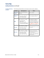
Summary of access methods
—
30

MasterSwitch VM User’s Guide v
Contents
ProductInformation ..........................
31
WarrantyInformation ..........................31
Limited warranty
—
31
Obtaining service
—
31
Warranty limitations
—
31
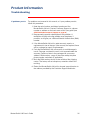
Troubleshooting...............................32
If problems persist
—
32
Life-SupportPolicy .............................33
General policy
—
33
Examples of life-support devices
—
33
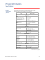
Specifications.................................34
Product specifications (
AP9222
)
—
34
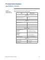
Product specifications (AP9221NX166)
—
35
Index
APCWorldwideTechnicalSupport

MasterSwitch VM User’s Guide 1
MasterSwitch VM
Introduction
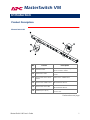
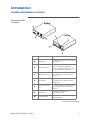
Product Description
MasterSwitch
VM
Continued on next page
No. Feature Description
!
Switched outlet
Provides individually managed
power control to outlets.
"
Outlet status LED
Indicates the state of the switched
outlet.
#
Overcurrent alarm silence
button
Silences the audible alarm.
$
Overcurrent audible alarm
Alertsyoutoanoverloadonthe
MasterSwitch VM unit.
%
Overcurrent alarm LED
Indicatesanoverloadonthe
MasterSwitch VM unit.
&
Modular ports (RJ11)
Connects a unit to the controller or to
another unit.

MasterSwitch VM User’s Guide 2
Introduction
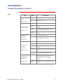
Product Description continued
MasterSwitch VM
Controller
Continued on next page
No. Feature Description
!
Status
LED
Indicates the status of the connection
with the unit.
"
Configuration Port
Connects the unit to a serial port on a
device running the appropriate
terminal emulation software in order
to access the Control Console
.
#
Modular port (
RJ11
)
Connects the unit to an Ethernet
LAN
for configuration or remote access
control.
$
Reset Button
Re-initializes the MasterSwitch
VM
network interface without affecting
outlet state.
%
10
Base-
T
network
port
Connects the unit to an Ethernet
LAN
for configuration or remote access
control.
&
Status
LED
Indicates the status of the
management card.
'
Link-
RX/TX LED
Indicates the status of the Ethernet
LAN
connection.

MasterSwitch VM User’s Guide 3
Introduction
Product Description continued
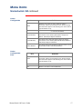
LED
s
LED Status Description
MasterSwitch
VM
Outlets
page 1
, Item 2
On The Outlet is on.
Off The Outlet is off.
MasterSwitch
VM
Overcurrent Alarm
page 1
, Item 5
Off The unit has no power.
Green
The unit is operating under normal load
conditions.
Flashing
green
The unit is approaching its maximum load.
(Warning threshold exceeded)
Solid red
The unit has exceeded its maximum load.
(>
100
%)
MasterSwitch
VM
Controller
Front Status
page 2
, Item 1
On The Controller has power.
Off The Controller has no power.
MasterSwitch
VM
Controller
Rear Status
page 2
, Item 6
Off The unit has no power.
Solid green The unit has valid network settings.
Flashing
green
The unit does not have valid network
settings.
Solid red
A hardware failure has been detected in the
unit.
Blinking
Red (Slow)
The unit is making
BOOTP
requests.
MasterSwitch
VM
Controller Rear
Link-
RX/TX
page 2
, Item 7
Off
The device which connects the unit to the
network (whether a router, hub, or
concentrator) is off or not operating
correctly.
Flashing
Green
The unit is receiving data packets from the
network.

MasterSwitch VM User’s Guide 4
Introduction
Operating MasterSwitch VM
Initial setup
You must configure the network settings of MasterSwitch
VM
before it
can operate on a network. The required settings are:
•
IP
address of MasterSwitch
VM
• Subnet Mask
•
IP
address of the default gateway
Note: If a default gateway is not present, enter an
IP
address
of a computer on the same subnet that is always active.
For instructions on configuring the MasterSwitch
VM
network settings,
see the installation manual included with the unit and on the
CD
. After
you have configured MasterSwitch
VM
, no further configuration is
required. The remaining MasterSwitch
VM
properties are pre-configured
at the factory. However, you may want to customize these properties for
your application. See
Menu Items on page 14
for more details on
changing MasterSwitch
VM
properties.
Configuring
outlets for
operation
MasterSwitch
VM
allows you to configure an outlet for on-demand
operation. On-demand operation consists of On, Off, and Reboot Outlet
Control Actions. The sections that follow desribe each operation that
you can configure for your MasterSwitch
VM
unit.
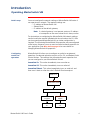
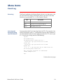
Immediate On. This action immediately turns an outlet on.
Immediate Off. This action immediately turns an outlet off.
Immediate Reboot. This action immediately turns an outlet off, and
then turns it back on after the outlet’s Reboot Duration expires.
Outlet is on
Immediate Reboot
command is issued
Outlet is turned off
Cancel command
is issued
Reboot Duration
expires
Outlet remains
off
Outlet is turned
on

MasterSwitch VM User’s Guide 5
Introduction
Operating MasterSwitch VM continued
Configuring
outlets for
operation,
continued
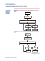
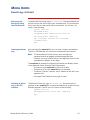
Delayed On. This action turns on an outlet according to its Power On
Delay.
Delayed Off. This action turns off an outlet according to its Power Off
Delay.
Continued on next page
Outlet is off
Delayed On
command is issued
Power On Delay
Cancel command
is issued
Power On Delay
expires
Outlet remains
off
Outlet is turned
on
Never
Delay
Outlet is on
Delayed Off
command is issued
Power Off Delay
Cancel command
is issued
Power Off Delay
expires
Outlet remains
on
Outlet is turned
off
Never
Delay

MasterSwitch VM User’s Guide 6
Introduction
Operating MasterSwitch VM continued
Configuring
outlets for
operation,
continued
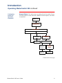
Delayed Reboot. This action turns an outlet off after the outlet’s Power
Off Delay expires. Once the outlet’s Reboot Duration expires, the outlet
is turned on.
Continued on next page
Outlet is on
Delayed Reboot
command is issued
Power Off Delay
Cancel command
is issued
Power Off Delay
expires
Outlet remains
on
Outlet is turned off
Never
Delay
Cancel
command is
issued
Reboot
Duration
expires
Outlet
remains off
Outlet is
turned ons

MasterSwitch VM User’s Guide 7
Introduction
Operating MasterSwitch VM continued
Configuring
outlets for
operation,
continued
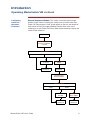
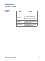
Sequenced Reboot. This action is available only through Master Outlet
Control. Initiating this action immediately powers off all outlets. Each
outlet will wait the longest Reboot Duration time (in seconds) in the set
of outlets on a MasterSwitch
VM
unit plus its own Power On Delay.
When these two delays expire, the outlet will be turned on.
Continued on next page
Outlet is on
Sequenced Reboot†
command is issued
Power On Delay
Cancel command
is issued
Power On Delay
expires
Outlet
remains off
Never
Delay
Outlet is
turned ons
Outlet is turned off
Longest
Reboot
Duration
expires

MasterSwitch VM User’s Guide 8
Introduction
Operating MasterSwitch VM continued
Configuring
outlets for
operation,
continued
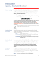
Delayed Sequenced Reboot. This action is available only through
Master Outlet Control. Initiating this action turns off outlets after their
Power Off Delay expires. Once all the outlets on the unit are turned off,
each outlet will wait the longest Reboot Duration time in the set of
outlets plus its own Power On Delay. When these two delays expire, the
outlet will be turned on.
Outlet is on
Delayed Sequenced
Reboot†
command
is issued
Power Off Delay
Cancel command
is issued
Power Off Delay
expires
Outlet
remains on
Never
Delay
Outlet is
turned offs
Power On Delay
Cancel command
is issued
Power On
Delay
expires
Outlet
remains off
Never
Delay
Outlet is
turned ons
Longest
Reboot
Duration
expires

MasterSwitch VM User’s Guide 9
Introduction
Operating MasterSwitch VM continued
Current sensing
Each MasterSwitch
VM
unit is equipped with a sensor that measures
the total current being used by the unit and devices connected to the
unit. The current measurement is displayed on the first screen that
appears when you log on and is used to generate alarms that you
define. The values displayed are:
• The aggregate current
• A percentage of the branch circuit rating, which is derived using
the following formula:
In the Unit Configuration section of the MasterSwitch
VM
menu, you can
define Overload Outlet Restrictions, conditions that generate an
Overload Audible Alarm, and the Low Current Threshold. (See
Unit
Configuration on page 16
for a detailed description of the items listed in
the menu.)
Do not exceed the maximum voltage and current ratings listed
on the label on the back of the unit.
Overload Outlet
Restrictions
Outlet Restrictions prevents users from turning on outlets when the
current sensor detects an overload condition. The following restrictions
can be set for each unit:
None
Outlets always turn on.
On Warning
Outlets do not turn on when the Overload Warning
Threshold has been exceeded.
On Overload
Outlets do not turn on when the full load percentage
exceeds
100
%.
Overload Audible
Alarm
You can customize the Overload Audible Alarm so that it never sounds,
it sounds when the load exceeds
100
%, or it sounds when the load
exceeds its Overload Warning Threshold. The value for the Overload
Warning Threshold can be set at a value that you determine based on
the needs of your system. If the Overload Audible Alarm is set to On
Overload Warning and the load exceeds the Overload Warning
Threshold, the Overload Warning
LED
flashes green and the alarm
sounds.
Low Current
Threshold
In addition to monitoring for overload conditions, the current sensor
monitors for low-current conditions. If current drops below the Low
Current Threshold that you have defined, the unit generates an
SNMP
trap to alert the host computer.
Note
: This item is available only in the
SNMP
interface.

MasterSwitch VM User’s Guide 10
MasterSwitch VM
Managing MasterSwitch VM
Management Interfaces
Overview
After you have configured MasterSwitch
VM
with the proper network
settings (see
Initial setup on page 4
), you can manage MasterSwitch
VM
remotely through its Web, Control Console, and
SNMP
interfaces.You
can also manage locally on the Control Console through a serial
connection. Only one user at a time can access MasterSwitch
VM
.
Serial connections (using a terminal emulator) have precedence over
Telnet users, and Telnet users have precedence over Web users.
Web interface
To access and log on to the MasterSwitch
VM
unit’s Web interface
perform these steps:
In the
URL
Location field, do one of the following:
• If the MasterSwitch
VM
unit’s Web port is set to the default
value of 80, type http:// followed by the MasterSwitch
VM
unit’s
IP
address. The following example shows a typical IP
address:
http://170.241.17.51
• If the MasterSwitch
VM
Web port is set to a value other than the
default of
80
, enter the System
IP
address (the IP address of the
MasterSwitch
VM
unit) followed by a colon and the configured
Web Port value (
8000
in the following example):
http://170.241.17.51:8000
• You can also enter the
DNS
name—this requires a
DNS
server
entry for the MasterSwitch
VM
unit. See the example below:
http://MasterSwitchVM25
Respond to the username and password prompts. The default
Administrator user name and password are both apc, all lowercase.
Note:
You can change the user name, password, and time-out values
in the System menu. See
User Manager on page 23
and
Outlet
User Manager on page 24
for more information.
Note:
Some Web interface features (data verification,
APC
Interactive
Assistant, and
MD5
authentication) require that you enable
JavaScript and/or Java. In order for
MD5
to function properly
you must also have cookies enabled on your Web browser.
Continued on next page

MasterSwitch VM User’s Guide 11
Managing MasterSwitch VM
Management Interfaces continued
Control Console
interface
In addition to using the Web, you can also manage MasterSwitch
VM
through the Control Console by one of the following modes of access:
• Telnet, for remote management
• A serial connection, for local management.
Telnet. To access the MasterSwitch
VM
unit’s Control Console using
Telnet :
1. Start a Telnet session and choose Remote System from the
Connect pull-down menu.
2. Type in the IP address of the MasterSwitch
VM
unit.
3. Click on the Connect button.
Serial connection. To access the Control Console using a serial
connection:
1. Use the supplied configuration cable (
APC
part number
940-
0024
C) to connect your serial port to the configuration port on
the MasterSwitch
VM
Controller.
2. Set the terminal port for the following communication settings:
Logging on. The procedure for logging on to the Control Console is the
same for both Telnet and a serial connection; respond to the user name
and password prompts.The default values of Administrator name and
password are both apc, all lowercase. You can change the username,
password and time-out values through the System menu. See
User
Manager on page 23
.
Structure. All menus in the Control Console list items by number and
name. To select an item, type in the number and press E
NTER
.For
menus that configure values, always use the
Accept Changes
option to
save any changes you have made.
Continued on next page
Item Setting
Baud Rate
2400
Data Bits
8
Stop Bits
1
Parity None
Handshaking None
Local Echo Off
Terminal Type
ANSI
(
VT100
)

MasterSwitch VM User’s Guide 12
Managing MasterSwitch VM
Management Interfaces continued
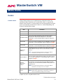
SNMP interface
MasterSwitch
VM
fully supports
SNMP
—all unit and outlet properties
are configurable through
SNMP
. For instructions on how to use
SNMP
to
manage MasterSwitch
VM
,seetheMibguide.pdf file in the Snmp folder
on the
CD
.
Auto-configuring
MasterSwitch
VM
Unit properties, outlet properties, and user accounts can be downloaded
to MasterSwitch
VM
from a configuration file. For details on auto-
configuring your MasterSwitch
VM
unit(s), open the README.txt file in
the apcConfigUtility directory on the
CD
. You can also find additional
information on the I2C utility on page 15 of the Management Card
Addendum.pdf locatedontheCD.

MasterSwitch VM User’s Guide 13
Managing MasterSwitch VM
Password-Protected Accounts
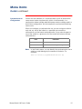
Overview
MasterSwitch
VM
provides three types of password-protected accounts
that allow you to control access to the MasterSwitch
VM
unit. Each type
of account provides a different level of access to the management
menus. There is one Administrator account, one Device Manager
account, and up to
16
Outlet User accounts.
Account access to
outlets and menu
items
Administrator and Device Manager accounts have access to all outlets.
Each Outlet User only has access to the outlets assigned to his or her
account. The Administrator account can configure and manage all other
accounts. For instructions on configuring Device Manager and Outlet
User accounts, see
User Manager on page 23
and
Outlet User Manager
on page 24
.
MasterSwitch VM
Main Menu Items
Account Type
Administrator
Device
Manager
Outlet
User
Outlets Yes Yes Yes
MasterSwitch
VM
Yes Yes No
Event Log Yes Yes No
Network Yes No No
System Yes No No
Logout Yes Yes Yes
Help Yes Yes Yes
Links Yes Yes Yes

MasterSwitch VM User’s Guide 14
MasterSwitch VM
Menu Items
Outlets
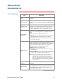
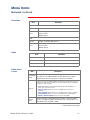
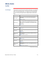
Control actions
Outlet Control Actions may be performed on individual outlets (by
Individual Outlet Control) or on all accessible outlets as a group (by
Master Outlet Control). A Control Action can only be applied to an outlet
that is not executing a command. If there is a command pending, the
State will be displayed orange.
†
Applies only when using Master Outlet Control
Continued on next page
Item Definition
Immediate On Turns outlet on.
Immediate Off Turns outlet off.
Immediate Reboot
Turns off the outlet immediately, waits the outlet’s Reboot
Duration time, and turns the outlet back on. For further
explanation, see the Immediate Reboot sequence diagram on
page 4
.
Delayed On
Turns on the outlet according to its Power On Delay. For further
explanation, see the Delayed On sequence diagram on page 5
.
Delayed Off
Turns off the outlet according to its Power Off Delay. For further
explanation, see the Delayed Off sequence diagram on page 5
.
Sequenced
Reboot
†
Immediately powers off all outlets. Each outlet waits the longest
Reboot Duration time plus its own Power On Delay and then
turns on.
Note
:
The longest Reboot Duration is the longest Reboot
Duration (in seconds) in the set of outlets.
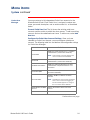
Delayed Reboot
Turns an outlet off after the outlet’s Power Off Delay expires.
Once the outlet’s Reboot Duration expires, the outlet is turned
on. For further explanation, see the Delayed Reboot sequence
diagram on
page 7
.
Delayed
Sequenced
Reboot
†
Turns off each outlet after its Power Off Delay. Once the outlets
are turned off, each outlet waits the longest Reboot Duration
time plus its own Power On Delay. When this delay expires, the
outlet turns on.
Note
:
The longest Reboot Duration is the longest Reboot
Duration (in seconds) in the set of outlets.
Cancel
Cancel all pending commands for the outlet(s).
Note
:
Outlet State is displayed in orange with an asterisk (*)
whenacommandispendingfortheoutlet(s).

MasterSwitch VM User’s Guide 15
Menu Items
Outlets continued
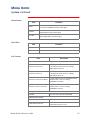
Synchronized set
configuration
Outlets that are members of a synchronization set will all execute the
same control action simultaneously (within
16
milliseconds). In a
configuration where multiple redundant power cords are being used in a
daisy-chain configuration, this feature permits synchronized switching
across units.
When you configure a synchronization set, you can assign an outlet to
only one set, and all the outlets in a specified set assume the
characteristics of the lowest numbered outlet. If you make changes to
any of the outlets in a given set, all of the outlets will take on the new
characteristics.
Note: In the Outlets menu, you can identify the synchronization set to
which an outlet belongs by the number in brackets. For
example:
(unit #: outlet # [synchronization set #])
Item Definition
Set Number Identifies a specific set of outlets.
Member Outlets Identifies the outlets assigned to a given set.
Page is loading ...
Page is loading ...
Page is loading ...
Page is loading ...
Page is loading ...
Page is loading ...
Page is loading ...
Page is loading ...
Page is loading ...
Page is loading ...
Page is loading ...
Page is loading ...
Page is loading ...
Page is loading ...
Page is loading ...
Page is loading ...
Page is loading ...
Page is loading ...
Page is loading ...
Page is loading ...
Page is loading ...
Page is loading ...
Page is loading ...
-
 1
1
-
 2
2
-
 3
3
-
 4
4
-
 5
5
-
 6
6
-
 7
7
-
 8
8
-
 9
9
-
 10
10
-
 11
11
-
 12
12
-
 13
13
-
 14
14
-
 15
15
-
 16
16
-
 17
17
-
 18
18
-
 19
19
-
 20
20
-
 21
21
-
 22
22
-
 23
23
-
 24
24
-
 25
25
-
 26
26
-
 27
27
-
 28
28
-
 29
29
-
 30
30
-
 31
31
-
 32
32
-
 33
33
-
 34
34
-
 35
35
-
 36
36
-
 37
37
-
 38
38
-
 39
39
-
 40
40
-
 41
41
-
 42
42
-
 43
43


American Power Conversion AP9222 User manual
- Category
- Power distribution units (PDUs)
- Type
- User manual
- This manual is also suitable for
Ask a question and I''ll find the answer in the document
Finding information in a document is now easier with AI
Related papers
-
American Power Conversion Master Switch User manual
-
-
-
-
-
-
APC WMR1000G User manual
-
-
-