Mosa TS 200 BS/EL | BS/EL P Owner's manual
- Category
- Welding System
- Type
- Owner's manual
This manual is also suitable for

MADE IN ITALY
C0FN7060003
• Motosaldatrice
• Engine Driven Welder
• Motosoudeuse
• Motosoldadoras
• Schweißaggregat
• Motosoldadora
• По Вышкам
• Lassers
COMPACT WELDERS
TS 200 BS/EL (STAGE V)
TS 200 BS/EL P (STAGE V)
Codice
Code
Code
Codigo
Kodezahl
Código
Код
Code
Edizione
Edition
Édition
Edición
Ausgabe
Edição
Издание
Editie
06.2019
USE AND MAINTENANCE MANUAL
TRANSLATION OF THE ORIGINAL INSTRUCTIONS – ENGLISH
language


11/01/01 C0FN7060_EN
ENGLISH
ENGLISH
INDex
0. GeNeRAL INFORMATION
M1.1
INTRODUCTION
................................................................................................................. PAG. 4
M1.4.2
CE MARK
........................................................................................................................... PAG. 5
M2
SYMBOLS AND SAFETY PRECAUTIONS
.............................................................................. PAG. 6
M2.1
WARNINGS
........................................................................................................................ PAG. 7
M2.5...
SAFETY RULES
.................................................................................................................. PAG. 8
1. GeNeRAL INFORMATION OF THe MACHINe
M0
DESCRIPTION OF THE MACHINE
........................................................................................ PAG. 12
RECORDING DATA
.............................................................................................................. PAG. 13
2. TRANSPORT AND HANDLING
M3
MACHINE UNPACKING
....................................................................................................... PAG. 14
M4.1
TRANSPORT AND HANDLING COvERED UNITS
................................................................... PAG. 15
3. INSTALLATION AND USe
M2.7
INSTALLATION
................................................................................................................... PAG. 16
M2.6
INSTALLATION ADvICES
..................................................................................................... PAG. 17
ELECTROMAGNETIC COMPATIBILITY
.................................................................................. PAG. 18
M25
SET-UP FOR OPERATION GASOLINE ENGINE
...................................................................... PAG. 19
EARTHING
......................................................................................................................... PAG. 20
M26.1
STARTING AND STOPPING GASOLINE ENGINE
.................................................................... PAG. 21
M30
CONTROLS LEGEND
.......................................................................................................... PAG. 22
M31
CONTROLS
........................................................................................................................ PAG. 23
M32
CONTROLS DESCRIPTION
.................................................................................................. PAG. 24
M34
USE AS WELDER
................................................................................................................ PAG. 25
M35
USE AS ENGINE STARTER
.................................................................................................. PAG. 26
M37...
USE AS GENERATOR
.......................................................................................................... PAG. 27
M38
REMOTE CONTROL
............................................................................................................ PAG. 29
4. INSTRUMeNTS USe
M55
RECOMMENDED ELECTRODES
.......................................................................................... PAG. 30
5. MANUTeNzIONe
M40.2...
TROUBLE SHOOTING
......................................................................................................... PAG. 31
M43
MAINTENANCE
.................................................................................................................. PAG. 33
MAINTENANCE SCHEDULED HONDA
.................................................................................. PAG. 34
M45
STORAGE AND DISASSEMBLE
........................................................................................... PAG. 35
6. INFORMAzIONI TeCNICHe
M1.5
TECHNICAL DATA
.............................................................................................................. PAG. 36
M1.6
TECHNICAL DATA
.............................................................................................................. PAG. 37
M2.7.1
DIMENSIONS
..................................................................................................................... PAG. 38
M60
ELECTRICAL SYSTEM LEGENDE
......................................................................................... PAG. 39
M61...
ELECTRICAL SYSTEM
........................................................................................................ PAG. 40
REV.0-06/19

10/10/02 M1-1_EN
ENGLISH
ENGLISH
REV.0-10/02
M
1.1
INTRODUCTION
Dear Customer,
We wish to thank you for having bought a high quality set.
Our sections for Technical Service and Spare Parts will work at
best to help you if it were necessary.
To this purpose we advise you, for all control and overhaul
operations, to turn to the nearest authorized Service Centre,
where you will obtain a prompt and specialized intervention.
+ In case you do not prot on these Services and some arts
are replaced, please ask and be sure that are used exclusi-
vely original parts; this to guarantee that the performances
and the initial safety prescribed by the norms in force are
re-established.
+The use of non original spare parts will cancel immediately
any guarantee and Technical Service obligation.
NOTES ABOUT THE MANUAL
Before actioning the machine please read this manual atten-
tively. Follow the instructions contained in it, in this way you will
avoid inconveniences due to negligence, mistakes or incorrect
maintenance. The manual is for qualied personnel, who knows
the rules: about safety and health, installation and use of sets
movable as well as xed.
You must remember that, in case you have difculties for use
or installation or others, our Technical Service is always at your
disposal for explanations or interventions.
The manual for Use Maintenance and Spare Parts is an inte-
grant part of the product. It must be kept with care during all
the life of the product.
In case the machine and/or the set should be yielded to another
user, this manual must also given to him.
Do not damage it, do not take parts away, do not tear pages and
keep it in places protected from dampness and heat.
You must take into account that some gures contained in it
want only to identify the described parts and therefore might
not correspond to the machine in your possession.
INFORMATION OF GENERAL TYPE
In the envelope given together with the machine and/or set you
will nd: the manual for Use Maintenance and Spare Parts,
the manual for use of the engine and the tools (if included in
the equipment), the guarantee (in the countries where it is
prescribed by law).
+ NOTICE: the manufacturer, who keeps the faculty, apart
the essential characteristics of the model here described
and illustrated, to bring betterments and modications to
parts and accessories, without putting this manual uptodate
immediately.
The Manufacturer shall not be liable for ANY USE OF THE PRO-
DUCT OTHER THAN THAT PRECISELY SPECIFIED IN THIS
MANUAL and is thus not liable for any risks which may occur as
a result of IMPROPER USE. The Company does not assume
any liability for any damage to persons, animals or property.
Our products are made in conformity with the safety norms in
force, for which it is advisable to use all these devices or informa-
tion so that the use does not bring damage to persons or things.
While working it is advisable to keep to the personal safety
norms in force in the countries to which the product is destined
(clothing, work tools, etc.).
Do not modify for any motive parts of the machine (fastenings,
holes, electric or mechanical devices, others..) if not duly au-
thorized in writing: the responsibility coming from any potential
intervention will fall on the executioner as in fact he becomes
maker of the machine.

10/10/02 M1-4_EN
ENGLISH
ENGLISH
1
2
16
18
19
20
21
22
23
24
25
26
27
28
29
30
31
32
33
34
17
3
45
6
6
7
8
9
10
11
12
13
12a
12b 12c
13
14
13a
13b 13c
13a
13b 13c
14
14a
14b
14c
14a
14b
14c
9
15
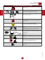
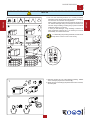
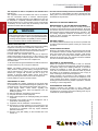
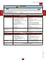
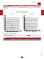
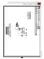
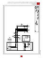
Any of our product is labelled with CE marking attesting its conformity to appliable directives and also the fulllment of safety
requirements of the product itself; the list of these directives is part of the declaration of conformity included in any machine
standard equipment.
Here below the adopted symbol:
CE marking is clearly readable and unerasable and it can be either part of the data-plate.
REV.7-02/18
M
1.4.2
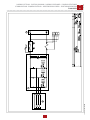
CE MARKING
ENGINE DRIVEN WELDER
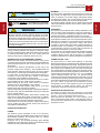
Furthermore, on each model it is shown the noise level value; the symbol used is the following:
The indication is shown in a clear, readable and indeleble way on a sticker.
1. Manufacturer name or brand
2. Year of production
3. Engine Driven Welder model
4. Serial number | registration number
5. Reference to the standard conr-
ming that the Engine Driven Welder
complies with its requirements
6. Welding process symbol
7. Symbol for Engine Driven Welders
which can be used an environment
with increased risk of electric shock.
8. Welding current symbol
9. OCV value (Rated no-load voltage)
or adjustment range between mini-
mum and maximum value
10. Reduced rated no-load voltage in
case of a voltage reducing device
(VRD)
11. Maximum and minimum welding
current values and relative voltage
value
12. Duty cycle symbol
12a. Duty cycle values
12b. Duty cycle values
12c. Duty cycle values
13. Rated welding current symbol
13a. Rated welding current values
13b. Rated welding current values
13c. Rated welding current values
14. Conventional load voltage symbol
14a. Welding voltage values
14b. Welding voltage values
14c. Welding voltage values
15. Auxiliary power supply symbol
16. Rated frequency
17. Power factor Cosϕ
18. Insulation class
19. Rated power (kVA/kW)
20. Rated voltage (V)
21. Rated current (A)
22. Rated power (kVA/kW)
23. Rated voltage (V)
24. Rated current (A)
25. Rated power (kVA/kW)
26. Rated voltage (V)
27. Rated current (A)
28. Engine symbol
29. Rated speed
30. Rated no-load speed
31. Rated idle speed
32. Engine maximum power
33. IP degree protection
34. Dry weight (kg)

13/11/14 M2_EN
ENGLISH
ENGLISH
REV.2-06/10
M
2
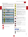
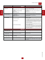
SYMBOLS AND SAFETY PRECAUTIONS
SYMBOLS IN THIS MANUAL
- The symbols used in this manual are designed to call your
attention to important aspects of the operation of the machine
as well as potential hazards and dangers for persons and
things.
Moreover, this symbolism intends to draw your attention
with the aim to give you indications for a correct use and,
as a result, to obtain a good operation of the machine or
equipment used.
SAFETY PRECAUTIONS
WARNING
This heading warns of situations which could result in injury
for persons or damage to things.
DANGEROUS
This heading warns of an immediate danger for persons as
well for things. Not following the advice can result in serious
injury or death.
CAUTION
To this advice can appear a danger for persons as well as
for things, for which can appear situations bringing material
damage to things.
IMPORTANT
NOTE
ATTENTION
These headings refer to information which will assis you in
the correct use of the machine and/or accessories.
!
!
!
!
!
!
SIMBOLS
STOP - Read absolutely and be duly attentive
Read and pay due attention
DANGER
!
GENERAL ADVICE - If the advice is not respec-
ted damage can happen to persons or things.
HIGH VOLTAGE - Attention High Voltage.There
can be parts in voltage, dangerous to touch. The
non observance of the advice implies life danger.
FIRE - Danger of ame or re. If the advice is not
respected res can happen.
HEAT - Hot surfaces. If the advice is not respected
burns or damage to things can be caused.
EXPLOSION - Explosive material or danger of
explosion. in general. If the advice is not respected
there can be explosions.
ACIDS - Danger of corrosion. If the advice is not
respected the acids can cause corrosions with
damage to persons or things.
PRESSION - Danger of burns caused by the
expulsion of hot liquids under pressure.
PROHIBITIONS
It is prohibited to smoke while lling the tank with fuel.
The cigarette can cause re or explosion. If the
advice is not respected res or explosions can
be caused.
It is prohibited to use water to quench res on the electric
machine
If the advice is not respected res or damage to
persons can be caused.
Use only with non inserted voltage -
It is prohibited to make interventions before having
disinserted the voltage.
ACCES FORBIDDEN to non authorized peaple.
ADVICE
Use only with safety clothing -
It is compulsory to use the personal
protection means given in equipment.
WRENCH - Use of the tools. If the advice is not
respected damage can be caused to things and
even to persons.

13/11/14 M2_EN
ENGLISH
ENGLISH
+ FIRST AID. In case the operator shold be sprayed by accident, from corrosive liquids a/o hot toxic gas or whate-
ver event which may cause serious injuries or death, predispose the rst aid in accordance with the ruling labour
accident standards or of local instructions.
+ FIRE PREVENTION. In case the working zone,for whatsoever cause goes on re with ames liable to cause severe
wounds or death, follow the rst aid as described by the ruling norms or local ones.
Skin contact Wash with water and soap
Eyes contact Irrigate with plenty of water, if the irritation persists contact a specialist
Ingestion Do not induce vomit as to avoid the intake of vomit into the lungs, send for a doctor
Suction of liquids from
lungs
If you suppose that vomit has entered the lungs (as in case of spontaneous vomit) take the subject to the hospital with the
utmost urgency
Inhalation In case of exposure to high concentration of vapours take immediately to a non polluted zone the person involved
EXTINCTION MEANS
Appropriated Carbonate anhydride (or carbon dioxyde) powder, foam, nebulized water
Not to be used Avoid the use of water jets
Other indications Cover eventual shedding not on re with foam or sand, use water jets to cool off the surfaces close to the re
Particular protection Wear an autorespiratory mask when heavy smoke is present
Useful warnings Avoid, by appropriate means to have oil sprays over metallic hot surfaces or over electric contacts (switches,plugs,etc.).
In case of oil sprinkling from pressure circuits, keep in mind that the inamability point is very low.
REV.2-06/10
M
2.1
WARNINGS

13/11/14 M2-5 (TS)_EN
ENGLISH
ENGLISH
REV.0-01/18
M
2.5
SAFETY RULES
ENGINE DRIVEN WELDERS
GENERAL SAFETY INSTRUCTIONS
+ NOTE: the information contained in this manual are
subject to change without notice.
The instructions in this manual are intended as indicative only.
It is the responsibility of the owner/operator to evaluate risks
and potential damages in relation to the use of the product in
the specic conditions of application. Remember that the non
observance of the indications of this manual may result in da-
mage to people or things.
In all cases, however, it is understood that the use shall be in
compliance with the applicable laws/regulations.
• Before operating the machine, read carefully the safety in-
structions contained in this manual and other manuals sup-
plied (engine, alternator, etc.).
• All operations, handling, installation, use, maintenance, re-
pair should be carried out by authorized and qualied per-
sonnel.
• When operating, wear personal protective equipment (PPE):
footwear, gloves, helmet, etc..
• The owner is responsible for maintaining the equipment in
safe conditions.
Use only in perfect technical conditions
The machinery or equipment must be used in perfect tech-
nical condition. Remove immediately any defects that may
affect the safe conditions of use.
• Before starting to use this equipment it is important to take
knowledge of all the controls of the machine, all its functions
and its correct installation in order to avoid accidents to pe-
ople and damage to the machine itself. In particular, it is
important to know how to stop the equipment quickly in case
of emergency.
• Do not allow the use of the machine to people unless pre-
viously instructed with all the information for a proper, safe
use.
• Forbid the access in the operational area to non authorized
personnel, children and pets so as to protect them from pos-
sible injury caused by any part of the machine.
SAFETY PRECAUTIONS DURING HANDLING AND TRAN-
SPORTATION
• Lift the machine using only the points allocated for this fun-
ction.
The lifting eye (or eyes) and the correct positioning of the
forks of the forklift are marked with specic adhesives.
• Clear the operational area of possible obstacles and all un-
necessary personnel.
• Always use lifting equipment properly sized and controlled
by enabled bodies.
• It is forbidden to set on the frame of the equipment objects
or accessories that alter weight and center of gravity and
cause stresses not foreseen to the lifting points.
• Do not submit the machine and the lifting equipment to
swinging or shock which may transmit dynamic stress to the
structure.
Equipments with trailers or site tows
• Never drag the machine without trailer (or site tow)
• Check for a correct assembly of the machine to the towing
device.
• Always make sure that the hook of the vehicle is suitable for
towing of the total mass of the trailer.
• Do not tow the trailer if the coupling devices are worn or
damaged.
• Check for proper tire pressure.
• Do not replace the tires with types different from the original
ones.
• Check that the brakes and the optical signaling of the trailer
are working properly.
• Verify that the bolts of the wheels are in place and well
tightened.
• Do not park the machine (on trailer or site tow) on a steep
slope.
For the stops, not followed by a work session, always enga-
ge the parking brake and / or block the wheels by means of
wheel chocks.
• Do not tow the trailer on bumpy roads.
• Do not exceed the maximum permissible speed on public
roads of 80 km/h with the trailer, in any case comply with the
legislation applicable in the country of use.
• Do not use the site tow on public roads, this is intended for
use only in private and delimited areas. The maximum per-
mitted speed is 40 km/h on smooth surfaces (asphalt or con-
crete), adapt in each case the speed to the type of ground.

13/11/14 M2-5 (TS)_EN
ENGLISH
ENGLISH
M
2.5.1
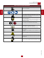
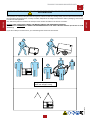
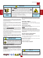
SAFETY PRECAUTIONS DURING INSTALLATION AND USE
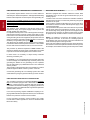
Do not instal equipments closed to heat source, to explosion
or re risk area.
10°
10°
= 20° max
10°
10°
= 20°
max
Always locate the machine on a at and solid ground, so as to
avoid tipping, slipping or falling during operation. Avoid using
the machine on slopes greater than 10 degrees.
1,5 m
1,5 m
1,
5 m
GAS
DI SCARICO
Make sure the area immediately surrounding the machine is
clean and free from debris
Do not place objects or obstructions in the vicinity of the air
intakes and air outlets, a possible overheating of the generator
could cause a re.
Connect the machine to an earthing system according to the
regulations in force at the place of installation.
Use the ground terminal on the front of the machine.
Do not use the machine with wet or damp hands and / or
clothing.
Use plugs suitable for the output sockets of the machine and
make sure that electrical cords are in good condition.
The machine must always be positioned so that the exhaust
gases are dispersed in the air without being inhaled by people
or living beings.
If you use the machine indoors is necessary that the installa-
tion is designed and built by skilled technicians in a workmanli-
ke manner.
During normal operation, keep doors closed. The access to
the internal parts should be allowed only for maintenance re-
asons.
Keep area near to the mufer free from objects such as rags,
paper, cardboard. The high temperature of the mufer could
cause the burning of objects and cause re
Immediately stop the machine in case of malfunction.
Do not restart the machine without rst having found and xed
the problem.
SAFETY RULES
ENGINE DRIVEN WELDERS
EXHAUST OUTPUT
REV.0-01/18

13/11/14 M2-5 (TS)_EN
ENGLISH
ENGLISH
M
2.5.2
SAFETY PRECAUTIONS DURING MAINTENANCE
Make use of qualied personnel to carry out maintenance and troubleshooting
It is mandatory to stop the engine before performing any main-
tenance on the machine.
Always use protective devices and suitable equipment.
Do not touch the engine, the exhaust pipes and the mufer
during operation or immediately after. Allow the engine to cool
before performing any operation
With the machine running pay attention to moving parts such
as fans, belts, pulleys.
Do not remove the protections and the safety devices unless
absolutely necessary, restore them after completion of the
maintenance or repair.
Do not refuel while the engine is running or hot.
Do not smoke or use naked ames when refueling.
Refuel only outdoors or in well ventilated areas.
Avoid spilling fuel, especially on the engine.
Clean and dry any leaks before restarting the machine
FUEL
Slowly unscrew the cap of the fuel tank and put it back always
after refueling.
Do not ll the tank completely to allow for expansion of the
fuel inside
Do not remove the radiator cap when the engine is running or
still hot, the coolant may spurt out and cause serious burns
Do not handle the battery without the use of protective gloves,
the battery uid contains sulfuric acid, which is very corrosive
and dangerous
Do not smoke, avoid any naked ames or sparks near the
battery, the vapors exhaled could cause the battery to explode
SAFETY RULES
ENGINE DRIVEN WELDERS
REV.0-01/18

13/11/14 M2-5 (TS)_EN
ENGLISH
ENGLISH
M
2.5.3
ADDITIONAL REQUIREMENTS FOR ENGINE DRIVEN WELDERS
Do not touch parts with OCV, it can cause mortal shock or
heavy born.
OCV is active at welding stick and auxiliary side when welding
generating set is working.
Do not manage electric devices and welding stick whit feet,
hands or wet dresses.
Protect yourself from electric shock by insulating yourself from
work and ground.
Use non-ammable, dry insulating material if possible, or use
dry rubber amts, dry wood or plywood, or other dry insulating
material.
Magnetic elds can affect pace-makers. Pace-maker wearers
keep away from arc welding and cutting operations and
equipment.
Wearers should consult their doctor before going near arc
welding, gouging, arc cutting, or spot welding operations.
Breathing welding fumes can be hazardous to your health.
Keep your out of the fumes
Use enought ventilation, exhaust at the arc, or both, to keep
fumes and gases from your breathing zone and the general
area.
If adequancy of ventilation or exhaust is uncertain, have the
air quality checked.
Arc rays can burn eyes and skin.
Use welding helmet with correct shade of lter.
While working protect your eyes using glasses with lateral
screen and your head with dedicated cap; in case of restricted
working area or unsafe working position also protect your
ears.
Wear complete body protection. Wear oil free protective
clothing such as leather gloves, heavy shirt, cufess pants,
and hight boots.
Welding can cause re or explosion.
Have a re extinguisher nearby, and have a trained re
watcher ready to use it.
Do not weld near ammable material. Move ammanles at
least (10 m) away or protect them with ame-proof covers.
Do not weld containers, structures, etc. with fammable
materials inside (tank, cylinder, etc.); in case you need to weld,
verify such items by qualied person in order to fully safely
operate.
Hot parts can cause severe burns.
Don’t touch the welder with bare hand. If handling is needed,
use proper tools and/or wear heavy, insulated welding gloves
to prevent burns.
Allow cooling period before handing parts or working on gun
or torch.
SAFETY RULES
ENGINE DRIVEN WELDERS
REV.0-01/18

11/01/01 C0FN7060_EN
ENGLISH
ENGLISH
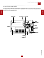
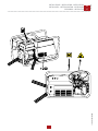
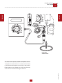
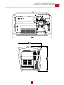
ALTERNATOR
VIBRATION
DAMPER
FRONT PANEL
FRAME
MUFFLER
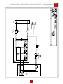
M
0
REV.0-06/19
LIFTING EYE
ENGINE
AIR FILTER
OIL DRAIN cAPOIL LEVEL
DIPsTIck
+
ENGINE OIL
REsERVOIR cAP
ENGINE
sTARTER
hANDLE
The TS 200 engine driven welder is a unit which ensures the function as:
a) a current source for arc welding
b) a current source for the auxiliary generation
Unit meant for industrial and professional use, powered by an endothermic engine; it is composed of various main parts such
as: engine, alternator, electric and electronic controls, the fairing or a protective structure.
The assembling is made on a steel structure, on which are provided elastic support which must damp the vibrations and also
eliminate sounds which would produce noise.
DeSCRIPTION OF THe MACHINe

0.1
RECORDING DATA
REV.1-11/14
The manual is for the range of machines indicated on the front cover.
With the scope to facilitate the search of the spare parts and maintain information of the bought machine, is necessary to record
some data.
Please write the requested data inside the squares to side:
1. Model of machine
2. Serial number of the machine
3. Serial number of the engine
4. Name of the dealer where bought the machine
5. Address of the dealer
6. Phone number of the dealer
7. Date of the bought machine
8. Notes
RECORDING DATA
1.
2.
3.
4.
5.
6.
7.
8.
16/10/15 Registrazione Dati_EN
ENGLISH
ENGLISH

30/03/00 M3_EN
ENGLISH
ENGLISH
NOTE
!
+ Be sure that the lifting devices are: correctly mounted,
adequate for the weight of the machine with it’s packaging,
and conforms to local rules and regulations.
When receiving the goods make sure that the product has
not suffered damage during the transport, that there has
not been rough handling or taking away of parts contained
inside the packing or in the set.
In case you nd damages, rough handling or absence of
parts (envelopes, manuals, etc.), we advise you to inform
immediately our Technical Service.
For eliminating the packing materials, the User must
keep to the norms in force in his country.
1) Take the machine (C) out of the shipment packing. Take out
of the envelope (A) the user’s manual (B).
2) Read: the user’s manual (B), the plates xed on the machine,
the data plate.
2
B
A
1
C
REV.1-02/04
M
3
MACHINE UNPACKING

15/01/01 M4_EN
ENGLISH
ENGLISH
Transportation must always take place with the engine off, electrical cables and starting battery disconnected and fuel tank empty.
Be sure that the lifting devices are: correctly mounted, adequate for the weight of the machine with it’s packaging, and conform
to local rules and regulations.
Only authorized persons involved in the transport of the machine should be in the area of movement.
DO NOT LOAD OTHER PARTS WHICH CAN MODIFY WEIGHT AND BARICENTER POSITION.
IT IS STRICTLY FORBIDDEN TO DRAG THE MACHINE MANUALLY OR TOW IT BY ANY VEHICLE (model with no CTM
accessory).
If you did not keep to the instructions, you could damage the structure of the machine.
Weight max. per person: 35 kg
Total max. weight; 140 kg
REV.2-09/11
M
4.1
TRANSPORT AND HANDLING COVERED UNITS
ATTENTION
!

11/01/01 C0FN7060_EN
M
2.7
INSTALLAzIONe - INSTALLATION - INSTALLATION
INSTALACIÓN - LUFTzIRKULATION - INSTALAÇÃO
УСТАНОВКА - INSTALLATIe
REV.0-06/19

13/09/18 M2-6 (TS) EN
ENGLISH
ENGLISH
If is needed to move the
welder machine be sure
that the engine is off, that
no electric connection is on
and that noone cable will
avoid to move the welder
machine.
The wrong loads distribution can cause
the instability of the vehicle and abnorma-
lities to wheel and components. In case of
transport need, use dedicated vehicle for
this purpose. The loads must be balan-
ced, xed in order to guaranty the stability
of the vehicle. Do not exceed the max load suitable of the vehi-
cle with reference to axle, wheels, etc. Fix the base of welder
machine at the frame or platform observing the instruction of
the vehicle producer
INSTALLATION AND ADVICE BEFORE USE
The operator of the welder is responsible for the security of the
people who work with the welder and for those in the vicinity.
Before installing the welder machine, read the safety instruction
of this manual at the chapter 2.5.
Particulary remember:
- installing operation must be made by authorized and qualied
person.
- while installing operation use individual safety devices (shoes,
gloves, cap, etc.)
INSTALLATION
FIxINg
MOVINg THE WELDER MACHINE
INSTALLATION ON VEHICLE
ATTENTION
This equipment is designed for outdoor use. It
may be stored, but is not intended to be used
when welding outside during precipitation unless
sheltered
!
M
2.6
INSTALLATION AdvIceS
eNGINe dRIveN WeLdeR
REV.0-09/18
DANgER
The machine must be positioned so that exhaust gas is dif-
fused without being inhaled by any living being.
Engine exhaust gas contains carbon monoxide, which is
harmful to one’s health, and in big quantities can cause in-
toxication and death.
Local norms in force have to be respected.
!
ATTENTION
A safe distance has to be kept between the machine and
fuel deposits, inammable goods (cloths, paper, etc.), che-
micals, according to indications provided by the authority in
charge. In order to avoid potentially dangerous situations,
area surrounding genset should be isolated so that unau-
thorized people will not be able to get close to the unit. Even
if The machines are manufactured according to electroma-
gnetic compatibility norms, we suggest NOT to install the
genset near machinery that can be inuenced by magnetic
elds.
!
Always instal the welder machine
on a hard and plan surface in order
to avoid rollovers, slips or falls whi-
le working;
avoid to use the welder machine
with slope more than 10°.
In order to absorb vibrations produced by gen-
set, it should be xed to a surface with suf-
cient rigidity, isolated against vibrations to-
wards other structures and with a mass equal
to at least three times the genset mass.
If such above could not be possible, be sure
that the welding machine do not move or slip
while working due to vibrations;
be care to x the welder machine with dedica-
ted tools.

10/06/00 Compatibilita Elettromagnetica (TS)_EN
ENGLISH
ENGLISH
ELECTROMAGNETIC COMPATIBILITY (EMC)
ENGINE DRIVEN WELDERS
REV.0-01/18
This equipment is built in compliance with standard IEC-
EN60974-10.
The equipment should be installed and used in accordance
with the information below to achieve electromagnetic
compatibility. The limits required by IEC-EN60974-10 may not
be adequate to completely eliminate interference when the
affected equipment is in close proximity or has a high degree
of sensitivity. In such cases it may be necessary to use other
measures to further reduce interference
warning
this Class A equipment is not intended for use in residential
locations where the electrical power is provided by the public
low-voltage supply system. There may be potential difculties
in ensuring electromagnetic compatibility in those locations,
due to conducted as well as radiated disturbances.
!
installation and use
The user is responsible for installing and using the arc welding
equipment according to the manufacturer’s instructions.
If electromagnetic disturbances are detected, then it shall be
the responsibility of the user resolve the situation with the
technical assistance of the manufacturer.
In some cases this remedial action may be as simple as
earthing the welding circuit (see note). In other cases, it could
involve constructing an electromagnetic screen enclosing the
welding power source and the work complete with
associated lters
In all cases electromagnetic disturbances shall be reduced to
the point where they are no longer troublesome.
note : The welding circuit may or may not be earthed for
safety reasons. Changing the earthing arrangements should
only be authorized by a person who is competent to assess
whether the changes will increase the risk of injury, for
example, by allowing parallel welding current return paths,
which may damage the earth circuits of other equipment.
Further guidance is given in IEC/TS 620812.
assessment of area
Before installing arc welding equipment the user shall make
an assessment of potential electromagnetic problems in the
surrounding area. The following shall be taken into account:
A) other supply cables, control cables, signalling and
telephone cables, above, below and adjacent to the arc
welding equipment;
B) radio and television transmitters and receivers;
C) computer and other control equipment;
D) safety critical equipment, for example guarding of industrial
equipment;
E) the health of the people around, for example the use of
pacemakers and hearing aids;
F) equipment used for calibration or measurement;
G) the immunity of other equipment in the environment. The
user shall ensure that other equipment being used in the
environment is compatible. This may require additional
protection measures;
H) the time of day that welding or other activities are to be
carried out.
The size of the surrounding area to be considered will depend
on the structure of the building and other activities that are
taking place. The surrounding area may extend beyond the
boundaries of the premises.
methods of reducing emissions
maintenance of the arc welding equipment
The arc welding equipment should be routinely maintained
according to the manufacturer’s recommendations. All access
and service doors and covers should be closed and properly
fastened when the arc welding equipment is in operation. The
arc welding equipment should not be modied in any way,
except for those changes and adjustments covered in the
manufacturer’s instructions.
welding cables
The welding cables should be kept as short as possible and
should be positioned close together, running at or close to the
oor level.
equipotential bonding
Bonding of all metallic objects in the surrounding area should
be considered. However, metallic objects bonded to the work
piece will increase the risk that the operator could receive
an electric shock by touching these metallic objects and the
electrode at the same time. The operator should be insulated
from all such bonded metallic objects.
earthing of the workpiece
Where the workpiece is not bonded to earth for electrical
safety, nor connected to earth because of its size and position,
for example, ship’s hull or building steelwork, a connection
bonding the workpiece to earth may reduce emissions in
some, but not all instances. Care should be taken to prevent
the earthing of the workpiece increasing the risk of injury to
users or damage to other electrical equipment.
Where necessary, the connection of the workpiece to earth
should be made by a direct connection to the workpiece, but in
some countries where direct connection is not permitted, the
bonding should be achieved by suitable capacitance, selected
according to national regulations.
screening and shielding
Selective screening and shielding of other cables and
equipment in the surrounding area may alleviate problems
of interference. Screening of the entire welding area may be
considered for special applications.

20/07/16 M25 (raff_aria)_EN
ENGLISH
ENGLISH
Check that the dry air lter is correctly installed and that there
are no leaks around the lter which could lead to inltrations of
non-ltered air to the inside of the motor.
DRY AIR FILTER
Vericare che il ltro aria a secco sia correttamente installato
e che non vi siano perdite intorno allo stesso che potrebbero
provocare inltrazioni di aria non ltrata all’interno del motore.
Fill the tank with gasoline for automobiles (preferably lead
free or with low lead content in order to reduce deposits in the
combustion chamber to a minimum).
For further details on the type of gasoline to use, see the motor
operating manual supplied.
REV.0-07/16
M
25
SET-UP FOR OPERATION
(GASOLINE ENGINE)
AIR COOLED
BATTERY WITHOUT MAINTENANCE
(WHEN ASSEBLED)
The supplied battery is generally ready for use.
Connect the cable + (positive) to the pole + (positive) of the
battery (after having taken away the protection), by properly
tightening the clamp.
On some models, the battery must be activated.
To activate it (ll the included acid) please follow the instructions
shown on the manual attached to the battery.
When battery is activated, DON’T add any other liquid.
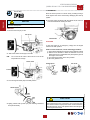
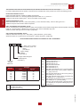
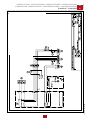
LUBRICANT
Please refer to the motor operating manual for the recommen-
ded viscosity.
To check the oil level:
1. Remove the oil-ll tap (24)
and clean the dipstick (23).
2. Insert the dip-stick into the
oil ller without screwing it
in.
3. If the oil level is low, ll with
recommended oil up to the
top of the oil ller
+ NOTE: before starting and switching off, see instructions in
the engine owner’s manual he-rewith attached.
MOTORS WITH OIL ALERT DEVICE
The “Oil Alert” system is designed to prevent damage to
the motor due to an insufcient quantity of oil in the cup.
This system automatically shuts off the motor before the
oil level falls below the safety limit.
If the motor does not start up again after shutting itself
off, check the oil level.
FUEL
ATTENTION
It is dangerous to ll the motor with too much oil, as its com-
bustion can provoke a sudden increase in rotation speed.
ATTENTION
Gasoline is highly ammable. Refuel with
motor shut off in a at surfaced well-venti-
lated area. Do not refuel in the presence of
ames. Avoid spilling fuel.
Any eventual spilled fuel and fumes are
ammable. Clean any dispersions of fuel
before starting up the motor.
!
!
Oil ll tap / dipstick
Upper oil level

14/10/13 Messa a Terra_EN
ENGLISH
ENGLISH
REV.0-10/16
Earthing
EARTHING WITHOUT GROUND FAULT INTERRUPTER
The protection against electric shock from contact indirect is
ensured by the “electrical separation” with equipotential bonding
between all the exposed conductive parts of the generating set.
The generating set is NOT equipped with a earth leakage circuit
breaker because its windings are not connected to ground,
hence the machine should NOT be intentionally connected to
a grounding circuit.
The limitation of the extension of the electric circuit is very
important for safety, do not power supply to electric plants with
a length greater than 200 meters.
It is important that the power cords of the equipment are equip-
ped with the protective conductor, yellow-green cable, in order
to ensure the connection between the exposed conductive parts
of the generating set and the equipment; this provision does not
apply to the class II equipment (double insulation or reinforced
insulation) recognizable by the symbol
.
The cables must be suitable environment in which it operates.
It should be noted that with temperatures below 5°C PVC cables
become stiff and PVC insulation tends to cut to the rst fold.
The protection by electrical separation is NOT suitable if the
machine is destined to supply power complex plants or located
in special environments with greater risk of electric shock.
In these cases it is necessary to adopt security measures
electricity provided by law.
For EXAMPLE, you can install a GFI (Ground Fault Interrupter
or Earth Leakage Circuit Breaker) high sensitivity 30mA, and
grounding the Neutral of the generating set: this operation
must be performed by a qualied electrician or at a authorized
service provider.
The grounding of the generating set is now mandatory to ensure
protection against indirect contact by means of the GFI.
Connect the generating set to an earthing system via a cable
certain efciency using the ground terminal (12) on the machine.
EARTHING WITH GROUND FAULT INTERRUPTER
The grounding connection to an earthed installation is obliga-
tory for all models equipped with a differential switch (circuit
breaker). In these groups the generator star point is generally
connected to the machine’s earthing; by employing the TN or TT
distribution system, the differential switch guarantees protection
against indirect contacts.
In the case of powering complex installations requiring or em-
ploying additional electrical protection devices, the coordination
between the protection devices must be veried.
For the grounding connection, use the terminal (12); comply
to local and/or current regulations in force for electrical instal-
lations and safety
EARTHING WITH ISOMETER
Machines equipped with insulation resistance monitor allow
intentionally not to connect the ground terminal PE (12) to an
earthing system.
Located on the front of the machine the insulation resistance
monitor has the function of continuously monitoring the ground
insulation of live parts.
If the insulation resistance falls below the pre-set fault value,
the insulation resistance monitor will interrupt the supply of the
connected equipment.
It is important that the power cords of the devices are provided
with the green-yellow circuit protective conductor, so as to en-
sure the bonding among all the grounds of the equipment and
the ground of the machine; the latter provision does not apply
to equipment with double insulation or reinforced insulation.
NOTE: it is possible to connect the PE terminal (12) to an
own ground connection. In this case an IT earthing system is
accomplished, this means with the active parts isolated from
earth and the equipment cases grounded.
In this case, the insulation resistance monitor checks the insula-
tion resistance of the active parts both towards case and ground,
for example, the insulation towards ground of the power cables.
Page is loading ...
Page is loading ...
Page is loading ...
Page is loading ...
Page is loading ...
Page is loading ...
Page is loading ...
Page is loading ...
Page is loading ...
Page is loading ...
Page is loading ...
Page is loading ...
Page is loading ...
Page is loading ...
Page is loading ...
Page is loading ...
Page is loading ...
Page is loading ...
Page is loading ...
Page is loading ...
Page is loading ...
Page is loading ...
Page is loading ...
Page is loading ...
Page is loading ...
Page is loading ...
Page is loading ...
Page is loading ...
-
 1
1
-
 2
2
-
 3
3
-
 4
4
-
 5
5
-
 6
6
-
 7
7
-
 8
8
-
 9
9
-
 10
10
-
 11
11
-
 12
12
-
 13
13
-
 14
14
-
 15
15
-
 16
16
-
 17
17
-
 18
18
-
 19
19
-
 20
20
-
 21
21
-
 22
22
-
 23
23
-
 24
24
-
 25
25
-
 26
26
-
 27
27
-
 28
28
-
 29
29
-
 30
30
-
 31
31
-
 32
32
-
 33
33
-
 34
34
-
 35
35
-
 36
36
-
 37
37
-
 38
38
-
 39
39
-
 40
40
-
 41
41
-
 42
42
-
 43
43
-
 44
44
-
 45
45
-
 46
46
-
 47
47
-
 48
48


Mosa TS 200 BS/EL | BS/EL P Owner's manual
- Category
- Welding System
- Type
- Owner's manual
- This manual is also suitable for
Ask a question and I''ll find the answer in the document
Finding information in a document is now easier with AI
Related papers
-
 Mosa TS 200 DES/EL Owner's manual
-
 Mosa TS 200 BS/CF Owner's manual
-
 Mosa TS 600 EVO Owner's manual
-
 Mosa DSP 500 YS Owner's manual
-
Mosa GM 7-200 HBT Owner's manual
-
 Mosa TS 405 EVO Owner's manual
-
 Mosa TS 400 YS Owner's manual
-
 Mosa Magic Weld 200 Owner's manual
-
 Mosa MAGIC WELD 200 YDE Owner's manual
-
 Mosa CS 230 YSX CC/CV Owner's manual


Other documents
-
Honda GX 610 standard Owner's manual
-
PowerSmart PS55 User manual
-
 Durostar DS4000WGE User guide
-
-
SDMO TECHNIC 15000 TE User manual
-
Ingersoll-Rand G110 Users Manual And Maintenance Manual
-
-
-
Kohler 200 C5 User manual
-
Crossfire CUB 190 ES Owner's manual
